5-Axis CNC Milling: A Practical Guide for Engineers
You're probably looking at a CAD model that made perfect sense in design review and now looks expensive to machine. Maybe it has a deep cavity with side features, a sculpted surface that needs to blend cleanly, or critical faces spread across several orientations. On a 3-axis mill, the part is possible, but only with multiple setups, custom workholding, and a growing chance that one repositioning step will push a key feature out of alignment.
That's the point where many engineers start asking the wrong question. They ask whether 5-axis CNC milling is overkill. The better question is whether staying on 3-axis creates hidden cost, hidden risk, and unnecessary lead time.
For simple prismatic parts, 3-axis is still the right answer. For cylindrical work with wrapped features, 4-axis often gets the job done. But when geometry, tolerance stack-up, surface finish, and delivery all start pulling against each other, 5-axis stops being a luxury option and becomes the practical one. It's not just about reaching more surfaces. It's about cutting the part in a way that protects accuracy, reduces handling, and avoids the fixture gymnastics that slow everything down.
Table of Contents
- Introduction When Your Design Exceeds 3-Axis Limits
- What Is 5-Axis CNC Milling
The simplest way to picture the five axes
Two common machine layouts
3-Axis vs 4-Axis vs 5-Axis Machining Compared- Comparison of 3-Axis, 4-Axis, and 5-Axis CNC Milling
Design for Manufacturability DFM Rules for 5-Axis Parts- Design choices that help instead of hurt
Material Tolerance and Finish Considerations- Where 5-axis earns its tolerance advantage
How 5-Axis Machining Impacts Cost and Lead Time- Why the higher machine rate can still save money
When to Specify 5-Axis Milling for Your Project- A practical selection filter
Introduction When Your Design Exceeds 3-Axis Limits
A familiar scenario. The part starts as a clean digital model with smooth transitions, angled ports, and features on several faces. Then manufacturing review begins, and the comments pile up. Split this operation. Add another fixture. Rotate the part. Leave extra stock. Accept more variation between features.
That's usually the moment when the design team realizes the problem isn't just geometry. It's the chain reaction caused by multiple setups. Every time an operator unclamps and re-fixtures a part, the process gets slower and the chance of positional error goes up. On straightforward components, that trade-off is manageable. On complex parts, it becomes the whole job.
A good way to think about 5-axis CNC milling is this: it doesn't just give the tool more motion. It gives the process fewer chances to go wrong. Features that would otherwise be machined from several orientations can often be completed in one clamping, with the tool kept at a more effective angle to the surface.
Practical rule: If your part looks easy in CAD but awkward in a vise, you're already in 5-axis territory.
Engineers usually justify the switch for one of three reasons. The part needs surfaces that a straight-down tool can't reach cleanly. The drawing requires feature relationships that are risky across repeated setups. Or the project timeline can't absorb fixture iteration and extra handling. Those are the real decision points. Geometry starts the conversation. Cost, lead time, and tolerance finish it.
What Is 5-Axis CNC Milling
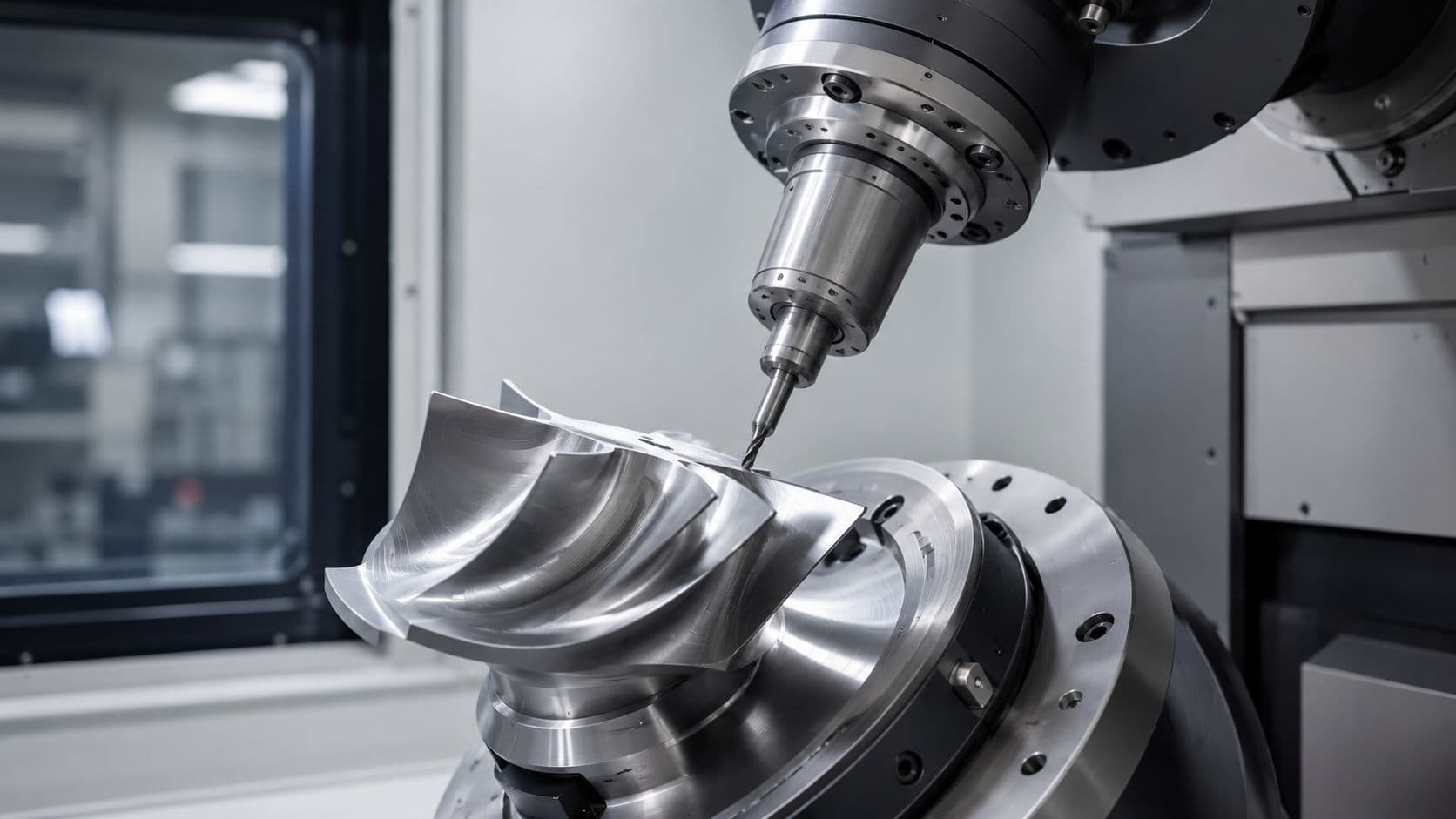
5-axis CNC milling uses three linear motions and two rotational motions to position the cutting tool relative to the part. The result is simple to describe even if the machine itself isn't. It lets the cutter approach the workpiece from far more useful angles than a standard vertical mill.

The simplest way to picture the five axes
Start with what most engineers already know.
- X-axis moves left and right.
- Y-axis moves forward and backward.
- Z-axis moves up and down.
That's standard 3-axis travel. If you picture a gantry moving a cutter over a block, you've got the basics.
Now add the rotational axes. The easiest analogy is a human wrist holding a pen over an object. Your arm can move in straight lines, but your wrist also tilts and rotates the pen so you can keep the tip aligned to the surface you're tracing. That extra articulation is what makes 5-axis effective. The machine isn't only moving to a point in space. It's orienting the tool for the cut.
In practice, that means the cutter can stay more nearly normal to a contoured surface, reach around obstacles, and machine deep or angled features without resorting to long, fragile tools whenever possible.
Two common machine layouts
You'll usually see 5-axis machines arranged in one of two ways.
Trunnion style machines rotate the table and tilt the part. The spindle still handles the cutting, but the workpiece moves into the right orientation. These machines are often a strong fit when shops need rigid support and reliable access to multiple faces.
Swivel-rotate style machines tilt the spindle head and may also rotate the table. Instead of moving only the part into position, the machine can aim the tool directly. That can be useful on large or awkward components where repositioning the workpiece is less practical.
Both layouts solve the same production problem. They reduce or eliminate the need to manually re-fixture the part between operations.
A 5-axis machine is less like “a 3-axis with two extras” and more like a machine that can keep the cutter in the right posture throughout the job.
That posture matters. The more naturally the tool meets the surface, the easier it is to control cutting forces, maintain consistency across blended geometry, and avoid the telltale witness lines that show up when a part has been approached from too many disconnected setups.
3-Axis vs 4-Axis vs 5-Axis Machining Compared
Choosing between 3-axis, 4-axis, and 5-axis isn't about chasing the most advanced option. It's about matching the machine to the part without paying for motion you don't need or forcing a simpler process onto a part that will fight it.
Comparison of 3-Axis, 4-Axis, and 5-Axis CNC Milling
| Attribute | 3-Axis CNC | 4-Axis CNC | 5-Axis CNC |
|---|---|---|---|
| Primary motion | X, Y, Z linear movement | X, Y, Z plus one rotational axis | X, Y, Z plus two rotational axes |
| Best fit | Flat parts, pockets, holes, prismatic geometry | Parts with features around a cylinder or multiple indexed sides | Complex surfaces, multi-face features, compound angles, organic geometry |
| Access to part faces | Limited without re-fixturing | Better access than 3-axis | Broad access in one setup for many complex parts |
| Setup burden | Often high on complex parts | Moderate | Lowest for difficult geometry |
| Programming difficulty | Lowest | Moderate | Highest |
| Fixture complexity | Often simple at first, then grows fast with complexity | Moderate | Can be simpler overall for complex parts because fewer reorientations are needed |
| Typical trade-off | Low machine cost, but extra setups on difficult work | Useful middle ground for rotary work | Higher machine and programming complexity, but stronger control over difficult parts |
| Good examples | Plates, brackets, housings | Shafts, wrapped features, indexed side work | Impellers, implants, turbine-style forms, angled manifold features |
How the choice affects the real job
For 3-axis, the main advantage is simplicity. It's familiar, widely available, and cost-effective for parts that can be machined from one or two straightforward orientations. If the drawing is mostly flat faces, open pockets, and standard drilled features, 3-axis is often the fastest path from quote to chips.
4-axis earns its place when the part wants rotary access but doesn't need full simultaneous tool orientation. Think of components with features spaced around the outside of a cylindrical body, or parts that benefit from indexing to several positions without fully re-fixturing by hand. It can cut a lot of waste out of the process without stepping into the full complexity of 5-axis programming.
5-axis becomes the right answer when every workaround starts adding friction. Deep cavities, compound-angle features, blended freeform surfaces, and parts with datums spread across many faces all push toward a process that minimizes handling.
Here's the practical difference. On 3-axis, a difficult part often becomes a sequence of compromises. The programmer breaks the part into setups. The machinist builds holding strategies around each side. Inspection has to confirm that every reorientation stayed true. On 5-axis, the strategy shifts. The team asks how to hold the part once, open access to critical surfaces, and preserve feature relationships from that single reference.
That doesn't mean 5-axis always wins. It can be the wrong choice for a simple block with a few drilled holes. It can also be wasteful when design intent doesn't require angular access or tight positional relationships between many features.
The best machine isn't the one with the most motion. It's the one that removes the fewest obstacles between your drawing and a repeatable process.
If you're deciding between them, look at the number of setups the part will require, not just the number of faces on the model. That's where cost and risk usually hide.
Design for Manufacturability DFM Rules for 5-Axis Parts
The most efficient 5-axis parts aren't the most dramatic-looking ones. They're the parts designed with tool access, workholding, and process stability in mind from the start.

Design choices that help instead of hurt
A few DFM habits make a measurable difference.
- Standardize internal radii where you can. Every unusual corner radius can force a tool change, a slower pass, or both. If adjacent features can share the same cutter, the toolpath gets simpler and the job becomes easier to stabilize.
- Give the tool a clean line of access. Deep narrow cavities are still difficult on a 5-axis machine if the tool has to reach too far with too little clearance. The machine can tilt the tool, but it can't change basic cutter stiffness.
- Don't specify impossible sharp internal corners. End mills are round. If the mating part truly needs a relieved corner, call it out deliberately. If it doesn't, let the machinist use a sensible radius.
- Watch wall thickness on tall features. Thin walls can deflect during machining, especially when surrounded by aggressive roughing or when final finishing leaves too little support.
- Use 5-axis to reduce fixtures, not excuse poor workholding. The process still needs a stable way to grip the part and expose the right surfaces. Tiny contact areas and flimsy tabs can turn an advanced machine into a vibration generator.
A broader design for manufacturability guide for engineering teams is useful here because the same principle keeps showing up across processes. The part that's easiest to inspect, hold, and machine is often the part that gets delivered fastest.
The thermal stability issue engineers often miss
Most discussions about 5-axis machining focus on theoretical capability. Shops can hit very tight numbers on paper. But the shop floor has another variable that engineers often overlook. Temperature.
The hidden cost of machine warm-up and environmental instability matters when the print is tight. In uncontrolled conditions, dimensional drift can reach up to 0.015 mm, and smart thermal compensation systems with real-time sensor feedback have been reported to reduce drift by 60% in mid-sized shops, as discussed in this thermal stability discussion on 5-axis machining.
That matters most on regulated and high-reliability work. Medical parts, aerospace hardware, and automotive programs with strict traceability don't just need a machine capable of precision. They need a process that stays stable from the first part of the day to the last.
Shop-floor reality: A machine that hasn't thermally settled can miss a tolerance without any dramatic sign during cutting.
When specifying a critical part, ask practical questions. How is the machine warmed up? How is coolant temperature managed? Is the process built around stable inspection and documented control, or just machine capability on a brochure? Those answers often tell you more than the axis count.
Material Tolerance and Finish Considerations
The biggest tolerance advantage of 5-axis milling doesn't come from magic. It comes from fewer opportunities to lose alignment. When the part stays in one setup, feature-to-feature relationships are easier to preserve, and the process avoids the small locating errors that build up as a part gets moved from fixture to fixture.
Where 5-axis earns its tolerance advantage
For complex work, 5-axis CNC machining can consistently achieve positional tolerances of ±0.01 mm to ±0.02 mm, compared with the general 3-axis standard of around ±0.05 mm, according to Fictiv's overview of 5-axis CNC machining. That's one reason it's used for components such as turbine blades, orthopedic implants, and aerospace structures where cumulative setup error creates real risk.
That single-setup advantage changes inspection thinking too. When critical surfaces are machined relative to one clamping reference, CMM inspection becomes more straightforward because the features are more likely to reflect the same coordinate logic used during machining.
Material and finish decisions on the drawing
The finish side is just as important as tolerance.
A 5-axis machine can often keep the tool shorter and better oriented to the surface. In practice, that usually means less chatter, better blending across contoured shapes, and fewer visible transitions between toolpath regions. On metals such as aluminum, stainless steel, titanium, and nickel-based alloys, that tool control matters because the cut quality depends heavily on rigidity and approach angle. The same applies to engineering plastics, where poor support or excess tool length can leave smeared surfaces or dimensional instability.
When writing the drawing, a few habits help:
- Call out critical tolerances selectively. Not every feature needs the same control. Reserve tight positional requirements for surfaces that affect fit, sealing, alignment, or performance.
- Differentiate cosmetic finish from functional finish. A visible consumer-facing face may need one requirement. A sealing face or bearing interface may need another.
- Match finish requirements to process reality. If a surface will be bead blasted, anodized, polished, or coated after machining, specify the finish in the context of the final part state.
If your team needs a quick reference for finish terminology, this surface roughness chart covering Ra, Rz, and finish selection is useful when aligning drawing notes with what the machine process can realistically deliver.
Don't tighten every tolerance because 5-axis can be precise. Tighten the ones that protect function, and let the rest stay manufacturable.
That's usually how you get the primary benefit of the process without turning the quote into a penalty for unnecessary control.
How 5-Axis Machining Impacts Cost and Lead Time
Engineers sometimes lose the cost argument for 5-axis because the machine hourly rate is higher. That's a narrow view. The meaningful comparison isn't machine hour versus machine hour. It's total job cost versus total job cost.

Why the higher machine rate can still save money
For complex geometries, 5-axis machining can reduce setup requirements by 60% to 80%, eliminating time lost to 5 to 10 different manual setups, according to Gimbel Automation's explanation of five-axis machining advantages. That same source notes that the shift to single-operation machining shortens cycle times and lowers fixture costs and labor hours.
Many quotes pivot at this stage. A 3-axis path may look cheaper at first because the machine itself is simpler. But once the shop has to design multiple fixtures, flip the part repeatedly, and inspect after each orientation-sensitive operation, the savings start to disappear.
A good cost review should include more than spindle time:
- Fixture effort: More setups usually mean more workholding design and more time proving it out.
- Operator handling: Every unclamp and re-clamp adds labor and another chance to damage or misplace the part.
- Inspection burden: Multi-setup parts often need more careful verification of feature relationships.
- Scrap exposure: The more process handoffs a part sees, the more ways it can fail late in the cycle.
For teams comparing options, a broader CNC machining cost guide for prototypes and production parts can help frame the quote beyond the hourly rate line item.
What slows projects down anyway
Lead time usually gets consumed in places engineers don't see at first. Fixture planning. CAM revisions. Waiting for a second operation. Reworking a surface because access was poor from the original orientation. Chasing one feature that drifted after a flip.
That's why 5-axis often helps most when schedules are tight. It compresses the process chain. The programmer can build around one primary holding strategy. The machinist spends less time touching the part between operations. Inspection sees a cleaner datum story.
FIRMFG is one example of a supplier that offers 3-, 4-, and 5-axis CNC machining for prototypes and low-to-mid volume production, which is useful when a project needs process selection based on the part rather than forcing every job into one machine category.
The trade-off is real, though. 5-axis asks for stronger CAM programming, better simulation discipline, and operators who understand collision risk, tool orientation, and fixture clearance. If the shop lacks that capability, the theoretical advantage won't show up in the delivered part.
When to Specify 5-Axis Milling for Your Project
The easiest way to decide is to stop thinking about 5-axis as a badge of complexity and treat it as a filter. If the part needs fewer setups, better tool approach, and tighter feature relationships than a simpler process can comfortably deliver, specify it.

A practical selection filter
Ask these questions during design review:
- Does the part have critical features on many faces? If yes, repeated re-fixturing may create more risk than the machine savings justify.
- Are there compound angles, undercuts, or sculpted surfaces? If yes, a straight-down toolpath will likely force awkward compromises.
- Do the important tolerances depend on one another spatially? If yes, keeping the part in one setup often protects the drawing intent better.
- Will fixture design become a project of its own? That's often the hidden sign that the process is wrong for the part.
- Is this a prototype or short run where fixture cost hurts? In lower volumes, avoiding elaborate workholding can matter as much as raw cycle time.
Good candidates for 5-axis
Some parts consistently justify the switch.
Medical implants with blended anatomical surfaces are strong candidates because form, finish, and positional accuracy all matter together. Aerospace components such as impellers, blisks, and structural parts with compound geometry also fit naturally. In robotics, end-effectors and lightweight structural parts often benefit when multiple mounting features need to stay true to one another across angled surfaces. High-performance automotive parts can fall into the same category when airflow paths, sealing faces, and mounting geometry all interact.
If your drawing is pushing past what a vise-and-flip process can handle cleanly, that's usually the answer already. The best time to specify 5-axis milling is before the team burns days trying to prove a 3-axis strategy that never really fit the part.
If you're weighing whether a part should stay on 3-axis or move to 5-axis, FIRMFG can review the geometry, material, tolerance, and volume requirements and help match the process to the job without overcomplicating the build.