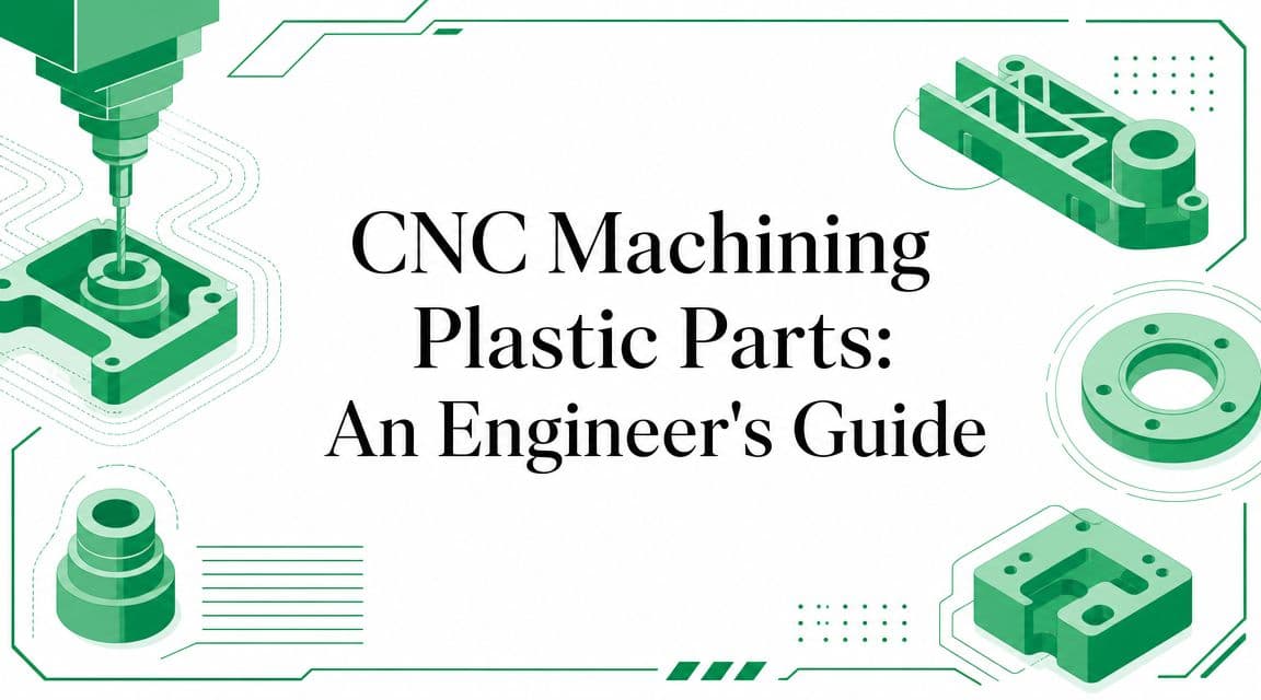
The ultimate guide to CNC machining plastic parts. Learn about materials, DFM rules, tolerances, costs, and how to choose the right supplier for your project.
You're probably looking at a CAD model that already works on screen. The assembly mates line up, the wall sections look reasonable, and the part seems simple enough to make. Then manufacturing starts asking awkward questions. Can that thin flange survive clamping? Does that pocket really need a sharp internal corner? Are you sure that cosmetic face can also be the datum face?
That's where CNC machining plastic parts stops being a quoting exercise and becomes an engineering decision. The process can produce precise, production-grade prototypes and low-volume parts in real materials, but plastics don't behave like aluminum and they definitely don't forgive casual design choices. Heat, clamping pressure, chip evacuation, and material stability all affect whether the part you modeled is the part you receive.
CNC is often the right bridge between rough concept validation and committed production tooling. It gives you real engineering plastics, strong surface finish control, and a direct path to functional testing without waiting on a mold. But it only works well when design intent matches manufacturing reality.
Table of Contents
- What separates a good result from a frustrating one
- Heat is the real process variable
- Why plastic parts fail differently
- How material choice changes the job
- Plastic material selection for CNC machining
- The main gotchas designers should expect
- Geometry that machines cleanly
- Features that look easy but drive scrap
- Tolerance is a cost decision
- Finish quality starts with the cut
- When CNC is the right answer
- When the other processes win
- What happens after unclamping
- Inspection has to match the material
- Questions that reduce risk early
- What good supplier feedback sounds like
From Digital Model to Physical Part
A familiar product-development moment goes like this. The industrial design is approved, the internal geometry is mostly settled, and the team needs a part that feels real enough to assemble, test, and trust. A printed mockup may confirm shape, and injection molding may be too early, too expensive, or too rigid for a design that's still moving.
That's where CNC machining plastic parts earns its place. It gives design teams a way to cut the part from real stock material rather than simulate the material with a printed approximation. That matters when the questions are no longer just “Does it fit?” but also “Does it seal, flex, slide, insulate, or hold alignment in the actual polymer we plan to use?”

Why teams land on CNC
3D printing is useful when speed matters more than exact material behavior. Injection molding is the right production process when volumes justify tooling and the design is stable enough to lock. CNC sits in the middle and sometimes stays there. It's often the process teams use for functional prototypes, bridge production, fixtures, and specialized low-volume parts that still need good dimensional control and a clean finish.
The practical advantage is simple. CNC lets you test the design you care about, in a plastic that behaves much closer to the final application than a placeholder prototype material.
**Practical rule:** If the prototype needs to answer mechanical, thermal, sealing, wear, or assembly questions, a machined plastic part usually tells you more than a visual model.
What separates a good result from a frustrating one
The machine can only cut what the design and process allow. A CAD model may be geometrically valid and still be expensive, unstable, or unreliable to machine in plastic. Teams usually discover this around deep pockets, long unsupported walls, cosmetic clear surfaces, and parts that need both tight tolerance and low distortion.
Good outcomes come from treating the part as a system. Material choice, cutter geometry, workholding, and tolerance strategy all need to support the same end use. If one of those decisions is off, lead time stretches because the shop has to slow the job down, rework the setup, or question the print.
Understanding CNC Machining for Plastics
Think of CNC machining as robotic carving. A programmed spindle removes material from a plastic block, plate, or rod until only the intended geometry remains. That sounds straightforward, but with plastics the difficulty isn't just removing material. It's removing material without changing the part while you cut it.
Metals tend to tolerate abuse better. Plastics don't. They soften earlier, expand more with temperature change, and react differently to tool pressure. That changes almost every machining decision.
Heat is the real process variable
For plastic machining, the main technical challenge is heat and cutting force. Guidance for plastics machining emphasizes that plastics can warp, melt, or crack if spindle speed, feed, chip load, or tool geometry aren't matched to the polymer, and recommends sharp tools, slower drill speeds for many plastics, and larger relief or clearance angles to reduce rubbing and heat buildup, as explained in American Micro Industries' guidance on effectively utilizing CNC machining for plastics.
A designer often sees the feature. A machinist sees the heat path.
A deep pocket, for example, isn't just a pocket. It's a place where chips can linger, rub, and warm the cut zone. A small drilled hole in acrylic isn't just a hole. It's a place where the wrong drill geometry can generate enough friction to haze, crack, or oversize the feature.
Why plastic parts fail differently
With metal, the obvious fear is tool wear or tool breakage. With plastic, the quieter failure mode is often part distortion. The toolpath may be correct and the machine may be stable, yet the part can still drift out of tolerance because the material deflects under cutting load or moves after local heating.
That's why process settings matter so much:
- Tool sharpness: Dull tools rub instead of shear. Rubbing builds heat fast.
- Controlled chip load: Too light can be as bad as too heavy because the tool skates and polishes instead of cutting.
- Clearance angles suited to plastics: The tool needs room to cut and evacuate chips without dragging on the wall.
- Material-aware drilling: Many plastics benefit from slower drilling approaches because drilling traps heat more easily than open milling.
A plastic part can come off the machine looking fine and still be dimensionally wrong after it cools or relaxes.
That's the part many teams underestimate. CNC machining plastic parts is less about brute machine capability and more about controlled energy. If you design and quote the job as if the plastic were aluminum, you'll usually pay for that assumption in scrap, cosmetic defects, or tolerance escapes.
Common Plastic Materials and Their Mathe regionbility
Material selection changes far more than strength, transparency, or chemical resistance. It changes how the shop holds the work, what tools cut cleanly, how much heat builds during machining, and how nervous everyone should be about the last finishing pass.
A manufacturing guide notes that about 80% of plastic parts are CNC milled, making milling the most widespread method for non-rotational plastic parts, and identifies common mathe regionble plastics such as ABS, polycarbonate, PEEK, POM, acrylic, and nylon in Geomiq's overview of CNC plastic machining. That broad material range is one reason CNC has become a practical default for prototypes and low-volume production.
How material choice changes the job
Some plastics cut cleanly and stay put. Others fight you by smearing, chipping, absorbing moisture, or moving after machining. The right question isn't “Can this material be machined?” Most can. The better question is “What compromises does this material force on tolerance, finish, and process stability?”
Here's a practical way to think about the common materials:
- ABS is a good general-purpose prototype material. It's useful for housings and covers, and it's usually forgiving compared with more brittle plastics. The main risk is heat-related surface quality on thin sections or sharp details.
- Acrylic works when optical clarity matters, but it punishes poor cutting conditions. It can chip, craze, or show cloudy edges if the tool geometry or feeds are wrong.
- Polycarbonate gives toughness and transparency, but it can gum up and mark if the cut runs hot. It's less brittle than acrylic, but cosmetic quality still takes care.
- POM (acetal/Delrin) is often a favorite for precision parts because it machines cleanly and holds shape well. It's a strong choice for low-friction mechanical features.
- Nylon works well for wear parts and moving components, but it can be less dimensionally predictable than designers expect, especially when the geometry is slender or the environment changes.
- PEEK sits in the high-performance category. It's chosen for demanding applications, but the material cost and process discipline usually make it a bad choice for casual prototyping unless the performance need is real.
For a broader overview of candidate resins and engineering grades, this guide to CNC machining materials is a useful starting point when you're narrowing the field.
Plastic material selection for CNC machining
| Material | Mathe regionbility Rating | Key Characteristics | Common Applications |
|---|---|---|---|
| ABS | Good | Tough, practical, general-purpose, decent for prototypes | Enclosures, covers, fixture components |
| Acrylic | Moderate | Clear, visually appealing, more brittle at edges | Display parts, light guides, transparent covers |
| Polycarbonate | Moderate | Tough, impact resistant, transparent option | Guards, lenses, protective panels |
| POM | Very good | Stable, low friction, clean cutting behavior | Precision mechanical parts, bushings, sliders |
| Nylon | Moderate | Wear resistant, useful for moving parts | Gears, guides, bushings |
| PEEK | Good but demanding | High-performance engineering plastic, costly to waste | Specialized industrial and technical components |
The main gotchas designers should expect
A material can be excellent in service and still difficult in manufacturing. That disconnect causes a lot of avoidable requotes.
**Material reality:** The best performing polymer on paper isn't always the best prototype material if the part needs thin walls, cosmetic surfaces, and fast iteration.
A few examples make the point:
- Clear plastics need process discipline: If appearance matters, ask early whether the part is “clear enough as machined” or needs a finishing plan.
- Soft or elastic plastics need gentler cuts: The issue isn't just surface finish. The material can move away from the tool.
- Expensive engineering plastics punish late design changes: If the geometry is still unstable, use that material only when the testing really requires it.
When teams choose the material with the machining process in mind, quotes tighten up and surprises drop. When they choose only from the application side, the shop has to solve problems that were designed in upstream.
Design for Manufacturability DFM for Plastic Parts
Plastic DFM isn't a list of generic rules. It's mostly about preventing distortion, chatter, poor finish, and unnecessary setup complexity. A feature may be technically mathe regionble and still be a bad production choice because the tool can't reach it efficiently, the wall moves during the cut, or the part won't stay stable in the fixture.
One of the most useful plastic-specific benchmarks is wall geometry. A design guide states that the standard minimum wall thickness is about 1.5 mm, recommends avoiding thin, tall walls with a width-to-height ratio of 3:1 as a rule of thumb, and notes that cutting depth beyond 2 to 3 times tool diameter reduces performance and raises cost, while cavities approaching 4 times tool diameter become increasingly expensive in RPWORLD's design advice for machined parts.

Geometry that machines cleanly
Start with wall thickness. In plastic machining, thin walls don't just risk breakage in use. They move during cutting. The tool pushes, the wall deflects, and the final pass doesn't remove material where you think it will. Then the part springs back after the cutter leaves.
Rounded internal corners matter for the same reason they matter in metal, but the plastic-specific issue is often finish and stress control rather than just tool access. A tiny inside radius forces a tiny cutter. Tiny cutters mean less rigidity, slower cutting, more heat concentration, and longer cycle time.
Use these design habits early:
- Keep walls above the practical minimum when possible: More section stiffness usually means better machining stability.
- Add internal radii generously: A larger cutter cuts cooler, faster, and more predictably.
- Avoid tall, unsupported features: If the wall acts like a spring, the machine will find out before inspection does.
- Design pockets with realistic depth-to-width relationships: Deep narrow geometry drives cost because reach, chip evacuation, and cutter stiffness all get worse together.
Features that look easy but drive scrap
Deep holes are a common trap. Designers often assume a drilled feature is cheap. It is, until the hole is deep enough for chip evacuation and heat to become the primary constraint. The same thing happens with narrow slots and cosmetic faces buried at the bottom of cavities.
Threads deserve the same skepticism. Plastics can take threads, but the feature should match the use case. If the assembly sees repeated service, overtightening risk, or small diameters, inserts may be more reliable than machining fine threads directly into the polymer.
A few design choices tend to create avoidable pain:
- Sharp internal corners increase machining difficulty and local stress.
- Very thin cosmetic rims chatter and leave inconsistent finish.
- Deep pockets with flat-bottom requirements often force smaller tools and longer runtimes.
- Datums placed on flexible faces make inspection and assembly harder because the reference itself moves.
The cheapest feature isn't the one that can be machined. It's the one that can be machined repeatably without special handling.
When a supplier sends back DFM comments on those points, that isn't resistance. It's usually the first warning that the design is asking for a result the process can't deliver economically.
Tolerances Surface Finishes and Tooling
Tolerance discussions often go wrong because the drawing treats every dimension as equally important. They aren't. Some surfaces locate bearings, seal against gaskets, or align optics. Others just define envelope. If you apply tight tolerance everywhere, the shop has to machine, inspect, and sometimes fixture the whole part as if every face were mission-critical.
That's expensive in plastic because holding size is only part of the job. The process also has to control heat and part movement.
Tolerance is a cost decision
Industry guidance reports that plastic CNC machining commonly achieves about ±0.005 in (±0.127 mm), that high-precision engineering plastics can reach ±0.001 in (±0.025 mm), and that ±0.05 mm or better may be achievable on difficult plastics when process control is strong, according to JLCCNC's plastic CNC machining guide. The important detail is the reason. Precision depends heavily on managing thermal expansion and process stability.
The practical analogy is simple. A family sedan and a Formula 1 car both have wheels, but they don't require the same build standard. If your part only needs a bracket hole pattern and a cosmetic outer profile, don't tolerance it like a sealing manifold.
Use tolerance intentionally:
- Tighten only what controls function: Fits, datums, sealing surfaces, bearing bores, and critical alignments.
- Relax nonfunctional dimensions: Outer stock cleanup and nonmating faces usually don't need premium process time.
- Match tolerance to polymer behavior: Stable plastics can support more ambitious requirements than softer or more temperature-sensitive ones.
- Expect price and lead time to rise with every unnecessary tight callout: The machine time is only one part of it. Setup, probing, inspection, and possible rework all increase.
Finish quality starts with the cut
A lot of buyers treat surface finish as post-processing. On plastic, surface quality starts much earlier. Tool sharpness, flute geometry, chip evacuation, and cutter engagement all determine whether the part comes off the machine clean or comes off needing rescue.
As-machined surfaces can be very good, especially on stable materials and simple geometries. But cosmetic expectations matter. A transparent cover, a visible consumer housing, and a hidden internal spacer should not all have the same finish requirement.
For teams comparing post-processing options, this overview of surface finishing methods for machined parts helps frame what should be solved in the cut and what can be improved afterward.
Over-specifying finish can be as costly as over-specifying tolerance, especially when the feature sits in a place the cutter can't reach cleanly in one setup.
Tooling choice ties both topics together. Tools intended for plastics generally need to shear cleanly and minimize rubbing. If the cutter drags, the dimension can still inspect acceptably on the machine and drift later because the material absorbed too much heat during cutting. That's why the right finish strategy starts with the right material, then the right tool, and only then the right secondary process.
CNC Machining vs Injection Molding and 3D Printing
The wrong process usually looks attractive at the start. 3D printing looks fastest, injection molding looks cheapest at scale, and CNC looks like the safe middle ground. In practice, the best choice depends on what question the part needs to answer right now.
If the question is visual form only, one process wins. If the question is functional performance in a production-grade polymer, another wins. If the question is long-run unit economics, the answer changes again.

When CNC is the right answer
Choose CNC when the part needs to behave like a real engineered component and you're not ready to commit to tooling. This is especially true for housings, fixtures, wear components, optical-adjacent parts, and assemblies where fit and function matter more than visual approximation.
CNC is a strong choice when you need:
- Production-like material behavior: You can machine real engineering plastics instead of approximating them.
- Tighter dimensional control on functional features: Good for mating parts, test fixtures, and prototypes that must assemble correctly.
- Low-volume flexibility: Design updates don't require mold changes.
- Good external finish straight off the machine: Especially on accessible faces and well-chosen materials.
Before the next comparison point, it helps to see a general overview of the trade space in motion:
When the other processes win
3D printing is the fastest way to learn whether the geometry basically works. It's useful for early fit checks, packaging studies, and conceptual enclosures. It struggles when the prototype must replicate the exact surface quality, transparency, or mechanical behavior of a machined engineering plastic.
Injection molding wins when the design has stabilized and volume justifies dedicated tooling. It can produce excellent parts repeatedly, but it asks for up-front commitment. Changes become slower because the mold becomes part of the design system.
There's also a useful contrarian point here. An independent plastics source notes that CNC machining can often achieve tighter tolerances than injection molding for plastic parts when workholding and thermal effects are controlled. That's one reason teams still use machining deep into validation and even for some low-volume production geometries.
A simple decision rule works well in practice:
| Project need | Best fit |
|---|---|
| Early shape and concept validation | 3D printing |
| Functional prototype in real material | CNC machining |
| Stable design with sustained production demand | Injection molding |
No process is universally better. Each one is better at answering a different stage-of-development question.
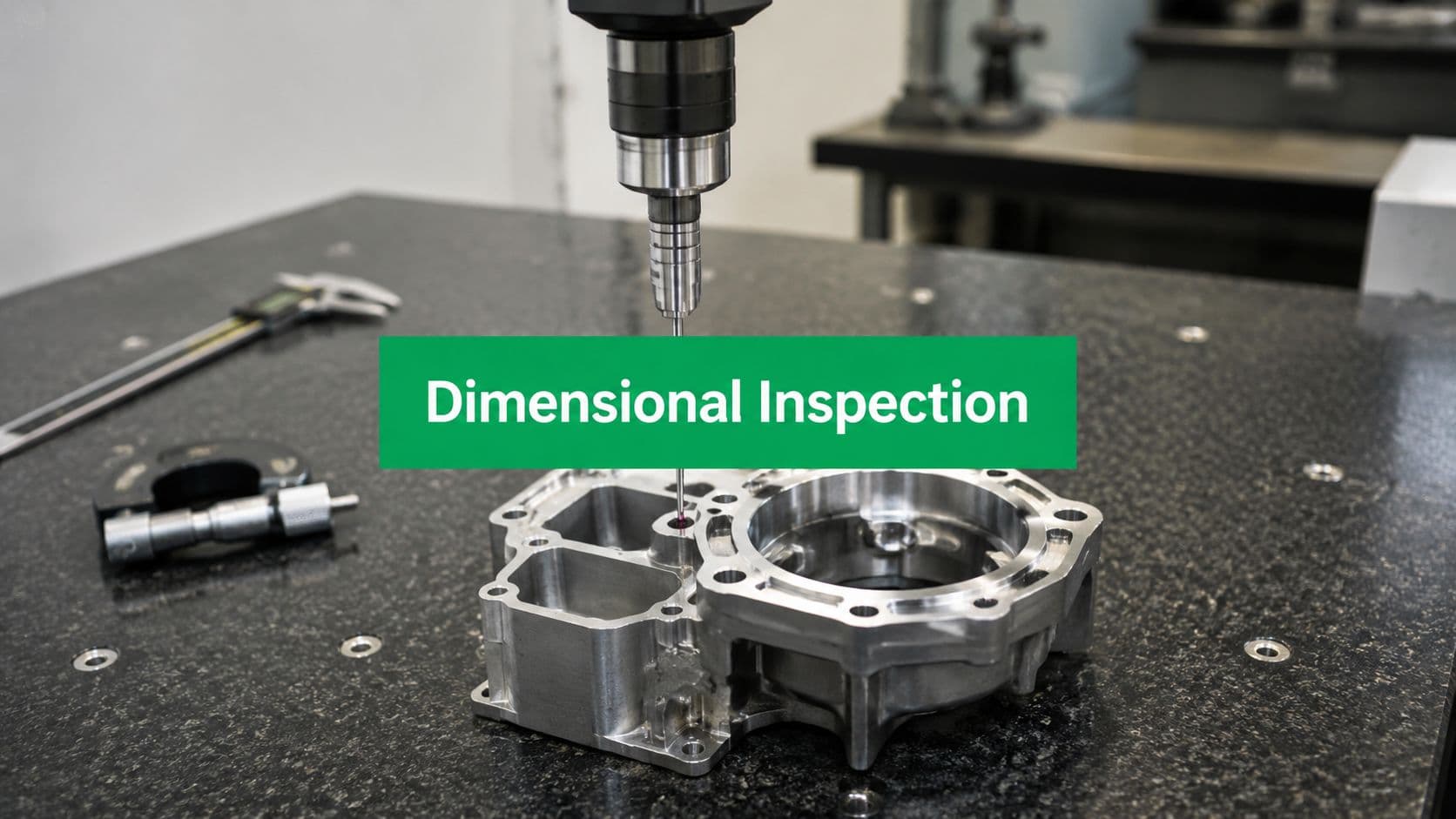
Inspection Quality Assurance and Fixturing
Inspection of plastic parts starts before the measurement report. If the workholding strategy introduces stress, the machine can cut a perfect shape relative to a temporary condition that disappears once the clamps release. That's why inspection and fixturing can't be separated in CNC machining plastic parts.
It is at this point that many sourcing decisions go sideways. Buyers compare machine lists and headline tolerances, but the harder question is whether the supplier knows how to stop the part from moving during and after the cut.
What happens after unclamping
A plastics machining source highlights a point that doesn't get enough attention. Plastic parts can move under clamp load and relax after cutting, so fixturing strategy and stress management become as important as tool choice, and CNC can often outperform injection molding on tolerance when workholding and thermal effects are controlled, as discussed in Ensinger's article on CNC machining and tight tolerances in plastic parts.
That shows up in several ways on the shop floor:
- Clamp distortion: The part is forced flat or forced square during machining, then springs away when released.
- Residual stress release: Roughing removes material that was balancing internal stress, and the remaining geometry moves.
- Thermal drift: Local heat changes dimensions enough to affect final passes or later inspection.
- Support mismatch: Thin or irregular parts sag unless the fixture supports the true load path.
A plastic part that measures correctly while clamped is not automatically a good part.
Inspection has to match the material
Good QA for plastics usually combines dimensional measurement with process awareness. A CMM report may verify bores, planes, and positions, but the measurement plan still has to respect how the part should sit in free state. Laser scanning can help with complex surfaces, but only if the datum strategy reflects the actual function of the part.
First article review becomes especially important when the geometry is flexible or the callouts are dense. A structured first article inspection process helps teams catch tolerance stack issues, datum mistakes, and fixture-induced distortion before the full batch is cut.
When reviewing a supplier's quality process, ask what happens if the part moves after roughing, after finishing, or after release. The answer should involve process adjustments, not just “we'll inspect it at the end.” For plastics, end-of-line inspection is necessary, but it isn't enough by itself.
Choosing a CNC Machining Partner for Plastic Parts
A supplier decision often sets the result before the first chip is cut. Two shops can quote the same CAD model, material, and tolerance band, then deliver very different parts because plastics expose weaknesses in process planning fast. The problems usually show up in predictable places: walls that move after unclamping, cosmetic surfaces marked by poor tool choice, and dimensions that pass in inspection but drift in assembly.
A shop that machines aluminum well is not automatically good at plastics. The spindle and control may be the same, but the process discipline is different. Plastic parts demand better control of clamping force, heat input, tool sharpness, stock condition, and inspection method. If a supplier treats plastic like softer metal, cost goes up and yield drops.

Questions that reduce risk early
The quote review is where good suppliers separate themselves. Price and lead time matter, but the useful signal is whether the supplier can explain how they will make the part hold shape, hold size, and stay inside the cosmetic requirement.
Ask questions like these:
- Which plastics do you machine regularly for parts like this? A useful answer includes specific resins, common feature types, and where those materials tend to move, chip, or polish poorly.
- What would you change in this model before release? Good feedback usually points to thin walls, deep pockets, sharp internal corners, weak datum surfaces, and finish-critical faces.
- How will you fixture this part without distorting it? If the supplier cannot explain support points, clamp strategy, or how they will finish the part in a relaxed state, the tolerance promise is weak.
- Which dimensions drive the process plan? Competent teams identify the few dimensions that control setup, sequence, and inspection instead of treating every callout as equal.
- How do you inspect a part that may move after roughing or after release? The answer should cover the measurement method, datum scheme, and what process change they make if the part does move.
These questions save time because they expose hidden cost early. A supplier who flags risk at quoting can prevent a redesign after first articles, a stalled build waiting on replacement parts, or a batch that looks fine on a report and fails in use.
What good supplier feedback sounds like
Useful feedback is specific. It ties your drawing to a machining consequence.
If a shop says a deep pocket needs a longer, smaller tool, that means more cycle time, lower stiffness, and a higher chance of tool marks or taper. If they say a large flat in UHMW is unlikely to stay flat to the print after release, they are telling you the tolerance is fighting the material, not the machine.
Look for responses like these:
| What they say | What it tells you |
|---|---|
| “This datum face is too flexible for repeatable inspection.” | They understand that measurement stability depends on part stiffness, not just CMM capability. |
| “We can machine this slot, but tool reach will raise cost and reduce finish quality.” | They are connecting geometry to cycle time, cutter deflection, and surface outcome. |
| “This resin can work, but a more stable grade gives you a better chance of holding that tolerance.” | They are matching material behavior to the requirement instead of accepting risk silently. |
| “We should cut a first article before releasing the full batch.” | They are controlling risk at the stage where changes are still cheap. |
The best suppliers do not just accept the file and issue a quote. They review the model the way a manufacturing engineer does. They ask which surfaces matter in assembly, which tolerances affect function, and where the drawing is asking the process to fight natural material movement.
That is the difference between buying machine time and buying a process. For CNC plastic parts, the better partner usually saves money by pushing back on the wrong details early and protecting the right ones all the way through production.