Master low volume CNC machining in 2026. Get expert insights on processes, materials, cost, DFM tips for tight tolerances, and project scaling.
You've got a prototype that works. The CAD is stable enough to stop changing every day, marketing wants pilot units, test engineers want more samples, and procurement is already asking whether it's time to talk about tooling. But jumping straight from one prototype to mass production is usually the wrong move.
That middle stage is where organizations either save time and money or create months of avoidable rework. If the design still needs validation, if demand is still uncertain, or if you need real engineering materials before committing to molds or dies, low volume CNC machining is often the cleanest path.
The key is to treat it as a decision framework, not just a buying category. The right machine strategy, material choice, tolerance callout, and supplier conversation can shorten lead time, avoid unnecessary setups, and keep the part functional without overbuilding it.
Table of Contents
- Why it works as a manufacturing bridge
- Milling choices based on geometry
- Turning and mill-turn for rotational parts
- Pick material by job, not by habit
- Finishes should solve a problem
- The quote is built before the spindle starts cutting
- Tighten only what affects function
- DFM choices that make precision easier
- Inspection has to match the print
- Choose 3D printing when speed beats everything else
- Choose CNC when the design needs real-world validation
- Choose molding when the design is stable
- What to check before you send the RFQ
- What a good supplier conversation looks like
What Exactly Is Low-Volume CNC Machining
If you need 100 parts after a successful prototype, you're no longer in pure prototyping. But you're also not ready for production tooling. That's the space low volume CNC machining fills.
A practical way to define it is roughly 10 to 10,000 pieces, a commonly cited range for the stage between prototype and full production, as outlined in PTSMAKE's overview of low-volume CNC machining. The number matters less than the role. This is the stage where teams build pilot runs, bridge production, market-test hardware, and replenish service parts without locking themselves into tooling too early.

Why it works as a manufacturing bridge
Think of it as a bridge between engineering confidence and commercial confidence. A one-off prototype proves a concept. A low-volume CNC run proves whether the part can be made repeatedly, inspected consistently, assembled without drama, and shipped on a realistic schedule.
That bridge matters because CNC machining doesn't require custom hard tooling to get started. Shops can work from digital files, fixtures, and machine setup instead of waiting for mold fabrication. That gives design teams room to learn before they commit.
**Practical rule:** If you still expect design changes, don't buy yourself into a tooling corner too early.
Typical use cases look like this:
- Pilot builds: You need enough parts to validate assembly flow, test fixtures, and field use.
- Bridge production: The product must ship before molding or casting tools are ready.
- Custom equipment: Annual demand stays low, so tooling never makes economic sense.
- Spare parts: Legacy products need replenishment in small batches.
Where teams get confused
A lot of teams treat low volume CNC machining as “just prototypes, but more of them.” That's not quite right. Once you move beyond one-offs, repeatability starts to matter more than raw speed. Fixturing matters. Tool access matters. Inspection planning matters.
If your team is still loose on drawings, datums, or revision control, that will show up immediately when you move into a real short-run build.
For anyone who needs a quick baseline on the process itself, this complete guide to CNC machining is a useful starting point before you start quoting parts for production intent.
Exploring Key CNC Processes for Production Parts
A design team sends over a housing with angled ports, side features, and a tight flatness callout on the mounting face. The first quoting mistake is usually the same. Someone assumes the most advanced machine is the safest choice. In practice, the right process is the one that makes the part in the fewest controlled setups while still holding the features that matter.

Milling choices based on geometry
3-axis milling should be the starting point for many low-volume production parts. It handles flat faces, pockets, drilled holes, contours on accessible surfaces, and other prismatic features with predictable setup cost. If the part can be machined from one primary orientation plus a simple flip, 3-axis often gives the best balance of price, lead time, and repeatability.
That matters because every extra setup adds risk. A second or third fixture can be completely reasonable, but each one creates another chance for positional variation, lost time, and inspection complexity.
4-axis milling makes sense when the part needs work around its perimeter or on several sides tied to the same rotational centerline. It reduces repeated manual re-fixturing and often improves feature-to-feature consistency on parts with side holes, radial patterns, or features wrapped around a body. For moderate complexity, this is often the practical middle ground between basic milling and full 5-axis work.
5-axis milling is justified when access drives the problem. Angled faces, compound geometry, deep features that need shorter tools, and surfaces that must relate tightly across multiple planes are common reasons to use it. Shops can reach difficult areas with fewer setups, which can improve accuracy and surface quality. The trade-off is machine time, programming effort, and sometimes longer queue time if 5-axis capacity is limited.
Design teams often ask for 5-axis to avoid DFM changes. That can work, but it is not free. If a small chamfer change, relief, or datum rethink lets the part run on 3-axis or 4-axis, the total job usually gets easier to quote, inspect, and repeat.
If your team needs baseline process language before reviewing supplier feedback, this CNC milling guide for designers and engineers is a useful reference.
Turning and mill-turn for rotational parts
If the part is primarily round, start with turning. Shafts, spacers, bushings, threaded pins, nozzles, and valve components are usually faster and more accurate on a lathe because the process matches the geometry.
That choice affects cost immediately.
A milled version of a round part usually means more material waste, longer cycle time, and weaker concentricity control than a turned version. Once the part also needs cross-holes, wrench flats, slots, or off-axis pockets, the decision becomes a routing question. Use turning with a secondary milling op when the added features are simple and quantities are low. Use mill-turn when those secondary features are frequent enough, precise enough, or numerous enough that moving the part between machines creates unnecessary handling and tolerance stack-up.
Here is the screening logic I use when reviewing CAD before quoting:
- Mostly flat or box-shaped: Start with 3-axis milling.
- Multi-sided with repeated perimeter features: Review 4-axis.
- Angled surfaces or difficult tool access: Review 5-axis.
- Round around a primary centerline: Start with turning.
- Round with several milled or drilled secondary features: Check mill-turn against a two-operation route.
Later in the selection process, this visual can help align engineering and procurement on machine choice.
The lowest hourly rate rarely gives the lowest part cost. The better choice is the process that makes the part with fewer setups, shorter tools, simpler inspection, and less operator intervention.
Choosing the Right Materials and Surface Finishes
Material selection goes wrong when teams spec the “strongest” option before they define what the part needs to survive. In low volume CNC machining, the right material is usually the one that meets function, machines predictably, and doesn't create unnecessary finishing work.
Pick material by job, not by habit
A useful way to narrow options is to group them by role.
| Material | Key Properties | Best For... | Relative Cost |
|---|---|---|---|
| Aluminum 6061 | Lightweight, corrosion resistant, generally easy to machine | Housings, brackets, fixtures, general-purpose structural parts | Lower |
| Aluminum 7075 | Higher strength than common general-purpose aluminum alloys, good weight-to-strength balance | Performance components, stiff lightweight parts | Medium |
| Mild steel | Strong, stable, durable | Machine bases, wear-tolerant hardware, structural parts | Medium |
| Stainless steel | Corrosion resistance, durability, clean appearance | Medical hardware, outdoor parts, harsh environments | Higher |
| Delrin (POM) | Low friction, stable, clean machining behavior | Bushings, insulators, sliding parts, precision plastic components | Lower to medium |
| ABS | Easy to machine, good for general non-structural use | Covers, housings, validation parts | Lower |
| PEEK | High-performance engineering plastic with strong thermal and chemical resistance | Demanding medical, industrial, and high-temperature applications | Higher |
A few practical rules help:
- Choose aluminum first when you need a balanced starting point for mechanical parts.
- Use stainless only when the environment demands it. Don't pay for corrosion resistance you don't need.
- Use engineering plastics deliberately. Delrin is often a cleaner choice than overcomplicating a metal part that only needs moderate strength and good dimensional stability.
- Reserve high-performance plastics like PEEK for applications that need their temperature, chemical, or regulatory performance.
Finishes should solve a problem
Surface finishing should answer a specific question. Do you need corrosion resistance, wear resistance, a cosmetic surface, lower glare, or a better feel in the hand?
Common choices usually fall into these buckets:
- As-machined: Best when function matters more than appearance and you want to avoid extra process time.
- Bead blasted: Useful for a more uniform matte look and for visually softening tool marks.
- Anodized aluminum: Chosen when aluminum parts need added corrosion resistance, surface hardness, or color coding.
- Powder coated: Better suited to durable cosmetic coverage on selected part types where coating thickness is acceptable.
**Selection shortcut:** Specify premium finish only on surfaces the product, assembly team, or end user actually interacts with.
If your team is comparing post-processing options in more detail, this surface finishing reference helps map finish type to function without over-specifying cosmetic work on noncritical faces.
Understanding the Factors That Drive Cost and Lead Time
Clients often look at a CNC quote and focus on material and unit price. Shops usually see something different first. They see setup burden, feature complexity, inspection risk, and whether your drawing forces slow work.
That's why two parts made from the same material can quote very differently.
The quote is built before the spindle starts cutting
In low volume CNC machining, non-cutting effort often dominates the economics. Verified industry guidance notes that setup and programming often matter more than spindle time, especially on runs from 1 to 100 parts, and that AI-assisted CAM and automated quoting are reducing some of that friction, as discussed in Dassault Systèmes' article on design tips for low-volume CNC production runs.
That matches what engineers see in practice. A simple part with clean datums and standard features may machine quickly and quote cleanly. A part with awkward workholding, deep pockets, tight profile tolerances, and several secondary operations can become expensive before cycle time is even fully optimized.
The main cost drivers
When reviewing a design for short-run production, I look at five levers first:
- Setup burden
CAM programming, fixture planning, tool selection, first-article proving, and inspection planning all happen before repeatable production starts.
- Machine choice
A part that can stay on a 3-axis mill usually costs less than one that forces 5-axis access or specialized turning capacity.
- Geometry complexity
Deep cavities, thin walls, tiny radii, and hard-to-reach features often mean smaller tools, slower feeds, and more tool changes.
- Tolerance and inspection load
The tighter the critical dimensions, the more process control and verification the shop needs to build in.
- Secondary operations
Deburring, blasting, anodizing, coating, marking, and special packaging all add time after machining.
If you want a faster quote and a cleaner schedule, remove avoidable complexity before sending the RFQ, not after.
What helps and what doesn't
Good habits that usually help:
- Bundle revisions carefully: Constant design churn resets programming and setup thinking.
- Define critical features clearly: Suppliers can focus effort where function matters.
- Keep cosmetic requirements realistic: Hidden surfaces don't need jewelry-grade attention.
- Group similar parts when possible: Shared setups can improve flow.
What usually hurts:
- Blanket tight tolerances across the full drawing
- Requesting premium finishing with no functional reason
- Changing geometry after quote approval
- Leaving material or inspection expectations ambiguous
Lead time behaves the same way cost does. Simple geometry, standard materials, and clear drawings move faster. Every special instruction adds coordination.
Achieving Precision with Tolerances and DFM
A design team releases a part with ±0.001 in called out across most of the print. The shop can make it, but the quote comes back high, lead time stretches, and inspection notes start piling up. In low-volume CNC, that outcome is common. Precision is not just a machine capability. It is a cost decision tied to function, process control, fixturing, and inspection.
The practical question is simple. Which dimensions need tight control for the part to work?

Tighten only what affects function
A good drawing tells the machinist where variation matters and where it does not. Critical dimensions usually sit on features that control fit, sealing, alignment, bearing location, thread engagement, datum relationships, or stack-up through assembly.
Before assigning a tight tolerance, run four checks:
- Does this feature mate with another part or define a datum?
- Does variation here change performance, preload, motion, or leak risk?
- Will this dimension affect assembly yield or field reliability?
- Can the shop inspect it repeatably without building a special measurement method?
If the answer is no, open the tolerance.
I see the same pattern on prototype and bridge-production parts. Teams often tighten dimensions to reduce risk, but broad tolerances do the opposite when they force extra setups, slower cuts, or inspection steps that add cost without improving function.
**Shop-floor reality:** The most expensive tolerance on the print is often attached to a non-critical feature.
DFM choices that make precision easier
DFM is the work of making the required tolerance achievable with a stable process. That usually means helping the cutter reach the feature, helping the part stay rigid in the fixture, and reducing variation between setups.
A few design choices have an outsized effect:
- Use internal radii the tool can produce: Very small corner radii push the shop toward smaller tools, lower material removal rates, and more deflection risk.
- Keep pocket depths and wall thicknesses realistic: Deep pockets and thin walls tend to move during machining, which makes size and flatness harder to hold.
- Standardize holes, threads, and chamfers: Common tooling reduces setup changes and lowers the chance of avoidable errors.
- Place critical features so they can be machined in fewer orientations: Every extra setup introduces another chance for location error.
- Call out fine surface finish only where the part needs it: Sealing faces, wear surfaces, and user-touch areas may justify it. Hidden nonfunctional faces usually do not.
- Give the shop stable workholding surfaces: If the part cannot be clamped consistently, the tolerance plan is weak from the start.
The business effect is direct. Parts that are easier to fixture and easier to reach usually cost less to machine and less to inspect.
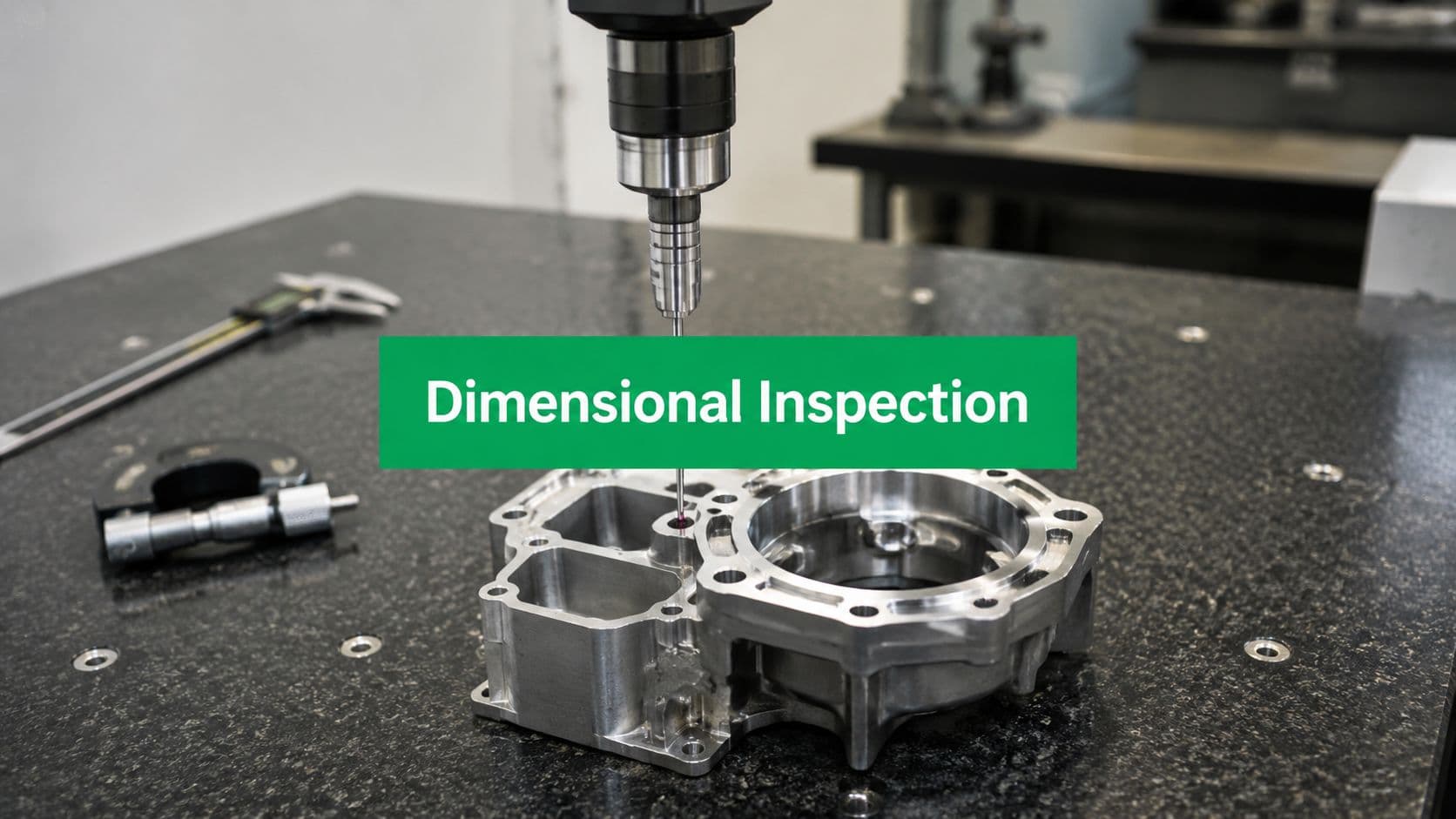
Inspection has to match the print
A tight drawing without a clear inspection path creates friction fast. If a feature is hard to probe, hard to datum correctly, or sensitive to part distortion after unclamping, the shop has to spend more time proving that the number on the report means something.
That is why inspection planning should happen at the same time as tolerance planning. Simple features may only need calipers, micrometers, or pin gauges. Positional relationships, profiles, and complex surfaces may require a CMM or other metrology equipment. The tighter the requirement, the more important it is to define datums cleanly and avoid ambiguous callouts.
A supplier such as LC Proto that starts with DFM review and uses tools such as CMM inspection and laser scanning fits jobs where feature verification needs to be thought through before production starts.
The main takeaway is practical. Precision comes from aligning three things: the function of the feature, a part geometry the shop can machine repeatably, and an inspection method that can verify the result without guesswork.
When to Choose CNC Over 3D Printing or Molding
The right question isn't “which process is best?” It's “which process fits the current stage of the product?”
Each option solves a different problem.
Choose 3D printing when speed beats everything else
If you need a shape in your hands fast, especially early in development, 3D printing is hard to beat. It's useful for form checks, basic fit checks, fixture concepts, and quick iterations before you've locked down all the engineering details.
It becomes less attractive when the part must represent final-machined material behavior, tighter dimensional control, or production-like surface and mechanical characteristics.
Choose CNC when the design needs real-world validation
CNC is usually the right middle-ground process when you need actual engineering materials, better dimensional stability, and repeatable production intent parts without committing to tooling.
That's one reason high-mix manufacturing has become more mainstream. The global CNC machine market was projected at $108.58 billion in 2026, with projected growth tied to demand for automation, precision, and efficiency, according to Fortune Business Insights on the CNC machine tools market. The strategic takeaway for design teams is straightforward. CNC supports switching between part numbers with far less tooling burden than molding-based routes.
Use CNC when you need:
- Production-intent materials
- Short-run bridge quantities
- Tighter geometry control
- Design changes without new molds
Choose molding when the design is stable
Injection molding makes sense after the design is settled and volume is high enough to justify the tooling investment. It's usually a poor fit when you still expect geometry changes, material changes, or assembly updates.
If you're still learning from each build, CNC keeps your options open. If the design is frozen and demand is predictable, molding starts to make sense.
A simple decision rule works well. Print for speed, machine for validation and bridge production, mold when the product is stable enough to amortize tooling through repeat demand.
How to Select and Partner with a CNC Supplier
A design team sends out an RFQ on Monday, gets three quotes back on Tuesday, and picks the lowest price by Wednesday. Two weeks later, the first article arrives with chatter marks on a sealing face, a drilled pattern shifted from datum, and no inspection report for the dimensions that matter. That is a supplier selection problem, not just a machining problem.
In low-volume CNC work, piece price is only one variable. The better decision is to judge a supplier on three things together: whether they can make the geometry, whether they can control the features that matter, and whether they communicate early enough to prevent avoidable scrap and delay.
What to check before you send the RFQ
Start by matching the shop to the job. A supplier that does simple 3-axis plate work well may still be the wrong fit for parts that need stable 5-axis positioning, thin-wall workholding, turned-milled features, or repeat setups across multiple batches.
Check these points before quoting:
- Process fit: Confirm the shop has the milling, turning, or multi-axis capability your part requires.
- Quality system: ISO 9001 usually indicates documented process control, revision handling, and traceability instead of informal shop-floor decisions.
- Inspection capability: Ask how they verify critical dimensions, what instruments they use, and whether CMM reporting is available when you need it.
- Material experience: Shops that machine your alloy or plastic regularly tend to catch burr, distortion, and tool-wear issues earlier.
- Capacity at your batch size: Low-volume work can be unattractive to some production shops. Make sure your order size fits their scheduling model.
Then evaluate how they quote.
A good supplier will question ambiguous callouts, surface finish notes that conflict with function, and tolerances that force unnecessary secondary inspection. If the quote comes back with no questions on a difficult part, I treat that as a risk signal. Good machinists do not stay silent when a print has problems.
What a good supplier conversation looks like
Send a complete package, not just a STEP file and a quantity.
Include:
- 3D CAD model
- 2D drawing with critical dimensions and tolerances
- Material specification
- Finish requirements
- Quantity and target schedule
- Notes on assembly-critical or cosmetic surfaces
That package gives the supplier enough context to make practical recommendations. They should be able to tell you where a radius is too small for efficient tooling, where a tolerance belongs on one feature instead of six, where workholding will mark a visible face, and where a cosmetic finish will add lead time without improving function.
The best supplier conversations are specific. Which features will be machined in one setup, and which need repositioning? Which dimensions will be checked in process, and which only at final inspection? If the material is prone to movement after roughing, do they plan to leave stock and come back for a finish pass? Those details affect cost, lead time, and yield.
You are not looking for a shop that only accepts files. You are looking for one that can explain the trade-offs before chips are cut.
LC Proto is one supplier to review for tight-tolerance prototype and bridge-production work. The company offers CNC machining and rapid prototyping, supports 3-, 4-, and 5-axis milling and turning, and states that each project starts with a DFM review followed by in-process and final inspection. For engineering teams, that combination is useful when the priority is clear quoting, manufacturability feedback, and parts built to print.
*Generated with Outrank*