Discover what is cnc milling in our 2026 guide. Explore the process, materials, tolerances, DFM tips, and manufacturing method comparisons.
CNC milling is a subtractive manufacturing process where a computer-controlled machine uses a rotating cutting tool to remove material from a solid workpiece and form the final shape. In practical terms, it's a robotic sculptor following a digital blueprint, and modern systems can reach general tolerances around ±0.1 mm, with precision systems capable of 0.025 mm.
You're probably here because a part looks perfect in CAD, but the actual question isn't the rendering. It's whether a shop can make it accurately, repeatedly, and without forcing a redesign after quoting. That's where CNC milling stops being a buzzword and becomes a decision tool for product teams.
For mechanical engineers, buyers, and startup hardware teams, the useful question isn't only what is CNC milling. It's also when to use it, what to watch for in design, and how to tell whether a supplier can hold the tolerances your part requires. CNC milling sits in the middle of that conversation because it turns digital geometry into physical parts with a level of control that manual machining can't match.
It's also not a niche process. One market report estimated the CNC milling machine tools market at USD 80.76 billion in 2023 and projected USD 111.94 billion by 2032 (SNS Insider on the CNC milling machine tools market). That scale reflects how extensively milling is embedded in aerospace, automotive, medical devices, and industrial equipment.
If you need a broader foundation first, this complete guide to CNC machining helps place milling within the larger machining field.
Table of Contents
- What the machine actually does
- Material choice changes the machining strategy
- What tolerance means in real projects
- What changes the final accuracy
- Where milling earns its place
- Manufacturing process comparison
Introduction From Digital Dream to Physical Part
A CAD model can hide a lot of manufacturing risk. Sharp internal corners look harmless on screen. Deep pockets seem easy until a cutter has to reach the bottom without chattering. A neat pattern of holes may be simple to draw but awkward to fixture. CNC milling is the process many teams use to close that gap between design intent and manufacturable reality.
The process resembles carving a part from a solid block with a robotic hand that never improvises. The machine follows programmed instructions, moves along defined axes, and removes only the material the program tells it to remove. That's why milling is often the process behind housings, brackets, fixtures, heatsinks, prototype enclosures, and many other prismatic parts with flats, pockets, slots, and drilled features.
What matters to a design team isn't only that the process is precise. It's that CNC milling gives you a practical path from one-off prototypes to low-volume production without changing the core manufacturing logic. You can test fit, revise geometry, tighten critical dimensions, and iterate without committing to hard tooling.
CNC milling is often the fastest way to learn whether your CAD model reflects a part that can actually be made, assembled, and inspected.
The most common confusion starts here. Many people hear “CNC machining” and “CNC milling” as if they mean the same thing. They don't. CNC machining is the umbrella term. Milling is one branch of it, defined by a rotating cutting tool removing material from a fixed workpiece.
For engineering teams, that distinction matters because the process itself shapes what you should design, what you should tolerate, and what you should quote against.
How CNC Milling Works From File to Part
The easiest way to understand milling is to follow the part through the shop. A designer creates geometry. A programmer turns geometry into tool motion. A machinist sets up the material and tools. Then the machine cuts.
A visual helps before the details.

The digital chain
The first step is the CAD model. This is the 3D definition of the part, including features such as holes, pockets, bosses, chamfers, and fillets. If the geometry is vague or overcomplicated, the machining process inherits that confusion.
Then comes CAM software. CAM doesn't decide what the part is. It decides how to cut it. The programmer selects tools, cutting sequences, entry methods, stepovers, depths of cut, and machining orientations. Real manufacturing judgment begins to show in these selections.
Next is G-code, the instruction set the machine reads. It tells the machine where to move, how fast to feed, when to change tools, and how deep to cut. You can think of G-code as the machine's sentence-by-sentence script.
**Practical rule:** If the CAD model defines shape, CAM defines risk. Most manufacturability issues show up in tool access, workholding, and cutting strategy, not in the idea of the part itself.
CNC milling is a subtractive process, meaning the machine removes material from a workpiece with a rotating tool. It's commonly used for slots, pockets, and complex contours, with general CNC machining tolerances often starting around ±0.1 mm, while precision systems can reach 0.025 mm (IQS Directory on CNC milling basics and tolerances).
After programming, the setup starts. The machinist secures the raw stock in a vise, fixture, or custom workholding setup. Tools are loaded into the machine. Offsets are set so the machine knows where the material sits relative to the coordinate system in the program.
What the machine actually does
Once the spindle starts, the rotating cutter removes material in passes. Roughing clears bulk material. Finishing passes clean up walls, floors, and visible surfaces. Drilling cycles create holes. Threading tools may add threads. If the part needs multiple sides machined, the setup may be changed or the machine may use additional axes to reach those surfaces in one run.
Here's a short video that shows the motion more clearly than text can:
A few points often surprise first-time buyers:
- The cutter has real physical size. Internal corners can't be perfectly sharp unless another process is used later.
- Tool length matters. Deep, narrow pockets are harder to machine cleanly than shallow, open ones.
- Setup influences cost. A part that needs multiple orientations usually takes more planning and handling.
That's why two parts with similar outer dimensions can quote very differently. The geometry, not just the size, drives the work.
Understanding the Machine Axes Tooling and Materials
When engineers ask what a mill can do, the answer usually comes down to three things. How the machine moves. What tool touches the material. What material is being cut.

Axes decide access
A 3-axis mill moves along X, Y, and Z. That covers left-right, front-back, and up-down motion. For many parts, that's enough. Flat faces, pockets, drilled holes, and basic contours all fit comfortably within 3-axis work.
A 4-axis or 5-axis machine adds rotation. The easiest analogy is your arm. A basic machine can move like your hand sliding across a table and moving up and down. A multi-axis machine adds wrist and forearm rotation, so the tool can approach surfaces from more useful angles.
Machine configuration changes what can be reached in one setup. Standard 3-axis platforms handle many common parts, while 4- and 5-axis systems add rotational motion that improves access to angled faces, undercuts, and asymmetric features. That's why 5-axis milling is preferred for intricate aerospace and medical parts, since fewer re-fixturings improve feature-to-feature accuracy (Wikipedia's overview of milling machine axis capability)).
For designers, the practical takeaway is simple:
- Use 3-axis when geometry is open and accessible
- Move to 4-axis when you need several sides without repeated reclamping
- Use 5-axis when angled surfaces, compound curves, or tight positional relationships matter
If you're comparing material and process options across common engineering grades, this machining materials overview is a useful reference.
Tooling shapes the result
The machine doesn't cut by magic. It cuts with tools chosen for specific jobs.
Some common examples:
- End mills handle general milling, side walls, pockets, and profiling.
- Ball nose mills are used for contoured surfaces and 3D forms.
- Face mills flatten larger surfaces efficiently.
- Drills make holes, usually faster and cleaner than milling a hole from solid.
Tool diameter affects what geometry is possible. A large cutter clears material fast but can't enter tight corners. A small cutter reaches finer detail but is less rigid and usually slower. Tool length matters too. Long-reach tools can access deeper features, but they're more likely to deflect or vibrate.
The limiting factor in a milled feature often isn't the machine travel. It's the cutter's ability to reach the feature without losing rigidity.
Material choice changes the machining strategy
A design team often starts with function. Strength, weight, corrosion resistance, insulation, appearance. The shop starts with mathe regionbility too. Those priorities meet in material selection.
Common milled materials include aluminum alloys, stainless steels, mild steel, brass, titanium, and engineering plastics such as ABS, polycarbonate, nylon, and Delrin. They don't behave the same under the cutter. Some materials evacuate chips cleanly. Others generate heat, stringy chips, or greater tool wear. Some plastics machine well but can deform if clamped too aggressively.
That affects more than cost. It also affects wall stability, surface finish, burr formation, and dimensional consistency after machining. A design that works in aluminum may need changes if the final part moves to stainless steel or plastic.
For product teams, this is the useful habit: pick material and geometry together, not one after the other.
Precision Tolerances and Quality Inspection
Tolerance is where many CNC milling conversations become expensive. Engineers specify dimensions. Shops decide how to hold them. If those two sides aren't aligned, the part may still be machined well and still be wrong for the job.
What tolerance means in real projects
A tolerance is the acceptable variation around a target dimension. If a feature is dimensioned at a nominal size with a stated tolerance, the finished part can vary only within that band. The tighter the band, the more control the process needs.

Modern CNC milling can achieve very tight tolerances. One technical source reports ±0.005–±0.01 mm under controlled conditions, while more typical industrial tolerances are often ±0.01–±0.05 mm (Cardinal Millwork on CNC machining history and tolerance capability). If your team needs a deeper grounding in how to specify these limits, this guide to CNC machining tolerances is a practical reference.
The key mistake is applying tight tolerances everywhere. Most parts don't need every face and feature controlled to the same level. Critical fits, bearing bores, sealing surfaces, and datum relationships deserve attention. Cosmetic or non-mating surfaces often don't.
What changes the final accuracy
Accuracy depends on more than the machine label.
Several factors matter in daily production:
- Machine rigidity: A stable machine deflects less under load.
- Tool condition: Worn tools can push material instead of cutting cleanly.
- Workholding: A part that shifts in the fixture won't match the program.
- Feature geometry: Thin walls and deep pockets are harder to hold accurately.
- Material behavior: Some materials move with heat or residual stress.
A tight tolerance can be easy on one feature and hard on another. A through-hole near the top surface is usually simpler than a deep internal pocket with a narrow floor. Designers often miss that difference because both look equally neat in CAD.
Ask for tight tolerances only where function demands them. That lowers cost and gives the shop room to focus control where it actually matters.
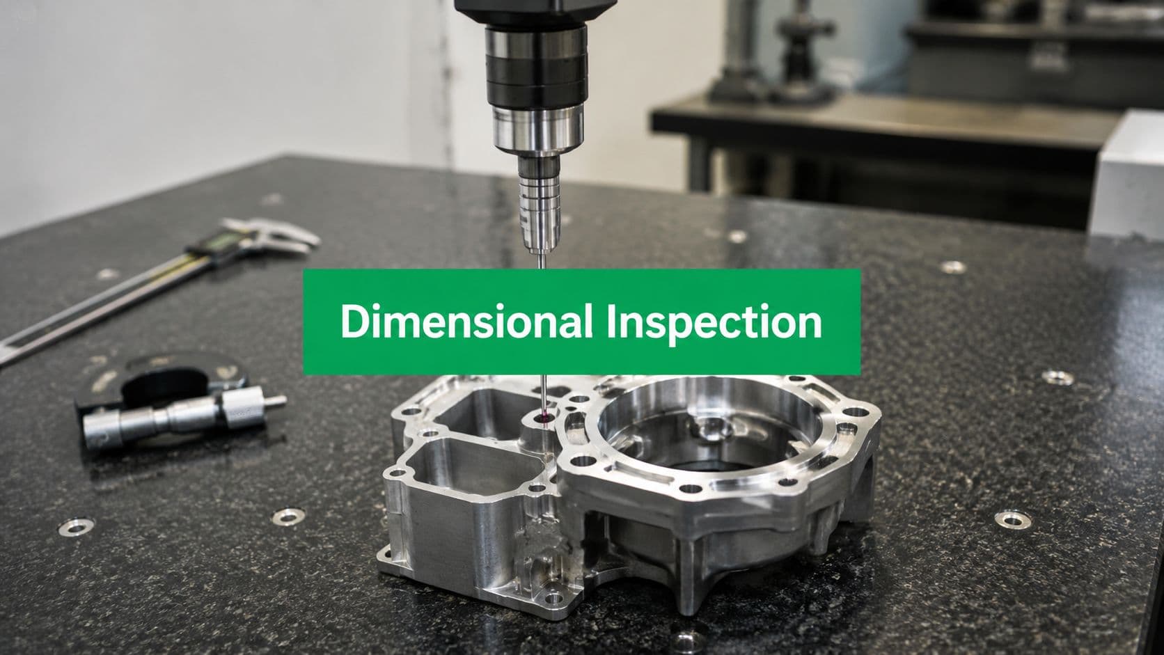
How shops verify the part
Inspection closes the loop between CAD intent and physical reality. Shops may use calipers and micrometers for basic dimensions, but complex parts usually need more capable methods.
Common inspection methods include:
| Inspection method | Best use |
|---|---|
| Calipers and micrometers | Fast checks on accessible dimensions |
| Height gauges and pins | Hole locations, simple comparative checks |
| CMMs | Complex geometry, positional relationships, inspection reports |
| 3D laser scanning | Surface comparison and fast geometry review |
Good suppliers don't treat inspection as cleanup after machining. They plan around it. That means datums are clear, critical dimensions are measurable, and the inspection method matches the tolerance risk.
Common Applications and Industry Use Cases
CNC milling becomes easier to understand when you attach it to actual parts instead of abstract process language.
Where milling earns its place
In aerospace, milling is commonly used for structural brackets, housings, fixtures, and components with weight-saving pockets or angled features. These parts often need a strong combination of geometric accuracy and material performance, which makes subtractive machining a practical choice.
In medical manufacturing, milling is used for surgical instrument components, device housings, and precision metal or plastic parts where fit and repeatability matter. A feature may be small, but if it locates another component or interfaces with a clinician's hand, consistency becomes critical.
In automotive work, milling often supports prototype engine components, EV hardware, jigs, fixtures, sensor mounts, and low-volume validation parts. Product teams use it because design changes are still happening and hard tooling would lock in decisions too early.
Electronics teams use milling for aluminum enclosures, heatsinks, brackets, and mounting plates. This is a common use case because milled parts can combine flatness, hole precision, and surface quality in a compact package.
A few patterns show up across industries:
- Prismatic geometry fits milling well. Brackets, blocks, housings, and plates are natural candidates.
- Functional features matter. Threads, slots, pockets, and precision hole patterns are common strengths.
- Prototype-to-bridge production is practical. Teams can iterate without changing the core process.
It's not that milling is everywhere. It's that teams use it when they need control over geometry, material, and tolerance at the same time.
CNC Milling vs Other Manufacturing Processes
A basic definition won't help much when your real question is whether milling is the right choice. That decision depends on geometry, material, quantity, and what dimensions matter most.
A common gap in introductory guides is that they explain the process but stop before giving a decision rule. Milling is strong for complex prismatic parts, but it can be less efficient than turning for cylindrical parts and more expensive than molding at high volumes (Hubs on CNC milling trade-offs and when milling is the wrong choice).

Manufacturing process comparison
| Process | Best for... | Material Choice | Typical Tolerance | Cost at Low Volume |
|---|---|---|---|---|
| CNC milling | Prismatic parts, pockets, slots, flat faces, precise hole patterns | Wide range of metals and engineering plastics | General CNC machining often starts around ±0.1 mm, with precision systems capable of 0.025 mm | Usually practical for prototypes and low-volume runs |
| CNC turning | Shafts, bushings, pins, and other cylindrical parts | Metals and plastics | High precision for rotational parts | Often more efficient than milling for round geometry |
| 3D printing | Complex internal forms, fast concept parts, organic shapes | More limited than machining in many production materials | Process-dependent and often chosen for speed or geometry freedom | Often attractive for early prototypes |
| Injection molding | Repeated plastic parts at production scale | Broad plastic selection | Good repeatability once tooling is built | Tooling makes low-volume work less attractive |
Use a simple screen when deciding:
- Choose milling if the part is mostly prismatic and needs machined features.
- Choose turning if the part is primarily round.
- Choose 3D printing if internal complexity matters more than machined finish or production material.
- Choose molding if design is stable and production volume justifies tooling.
Next Steps DFM Tips and Choosing a Supplier
Your team finishes the CAD model, sends it out for quote, and expects pricing to come back close and lead times to be straightforward. Then the questions start. How will the part be held? Can that pocket be reached with a standard tool? Do those tolerances all need inspection? That is usually the moment CNC milling stops being a definition and becomes a manufacturability decision.
Good results start before RFQ. A part can look clean on screen and still create avoidable cost through extra setups, custom tooling, fragile workholding, or difficult inspection. The practical goal is simple: design the part so a shop can hold it securely, machine it with predictable tools, and verify the features that matter.
DFM habits that save time
A few habits make that much more likely:
- Match internal corners to real cutting tools: End mills cut with a round profile, so sharp inside corners often force secondary processes or design changes.
- Limit deep, narrow features: A long tool behaves like a long paintbrush. The farther it reaches, the easier it deflects, chatters, or leaves a poor finish.
- Avoid overly thin walls: Thin sections can move during cutting, especially in softer metals and plastics.
- Apply tight tolerances selectively: Put precision on fits, sealing surfaces, hole locations, and other functional features. Broadly tolerancing every dimension tightly raises machining and inspection time.
- Leave the shop something solid to grip: Stable reference faces and clamping areas often matter as much as the feature being machined.
Datum strategy deserves early attention too. If the surfaces used for assembly are different from the surfaces used to locate the part in the machine, tolerance stack-up becomes harder to control. The best drawings make the inspection logic obvious. A machinist should be able to see which faces establish origin, which dimensions drive function, and which features are less critical.
A manufacturable part is one a shop can hold securely, cut cleanly, and inspect with confidence.
How to vet a supplier
Choosing a supplier is not just comparing quoted prices. You are choosing a process partner who will either catch risk before chips are cut or discover it after time and money are already spent.
For CNC milling, ask questions that reveal capability, not just capacity:
- Can they machine the part in the needed axis configuration without unnecessary rework?
- Do they review the model and drawing for DFM issues before release?
- How will they inspect the critical features on the print?
- Have they machined this material and tolerance range before?
- Will they flag likely problem areas such as thin walls, deep pockets, or difficult workholding surfaces?
A brief supplier conversation can tell you a lot. Strong shops talk in specifics: tool access, fixture plan, datum scheme, inspection method, and realistic tolerance bands. Weak answers stay generic.
LC Proto is one example in this space, with 3-axis, 4-axis, and 5-axis CNC machining, DFM review, and inspection support for prototype and low-volume parts. Whether you choose that supplier or another one, use the same screen. Clear feedback, realistic tolerances, and inspection methods that match the drawing are what reduce surprises.
Short FAQ
What usually drives CNC milling cost?
Complex geometry, multiple setups, tight tolerances, harder materials, and added inspection usually affect cost more than part size alone.
Is milling good for prototypes?
Yes. It is often a strong option when you need production-grade material, accurate functional features, and a part that behaves more like the final design intent.
When is milling the wrong choice?
Usually when the part is mostly cylindrical and better suited to turning, or when a stable plastic design has enough volume to justify molding.