CMM Inspection Services: A Practical Guide for Engineers
You've got the prototype in your hand. The machining looks clean, the finish is good, and the supplier says it's to print. That still leaves the key question: does the part match the design intent?
Teams often lose time when encountering issues such as these: a bracket assembles on one unit but binds on the next. A molded housing closes, but the gasket compression isn't consistent. A medical component looks perfect under a loupe and still misses a positional tolerance that matters in assembly. Visual confidence isn't metrology. For critical parts, you need a measurement method that can prove what the geometry is, not what it seems to be.
That's where CMM inspection services earn their keep. Used well, they shorten debug cycles, prevent bad release decisions, and give design and manufacturing teams a common set of facts. Used badly, they create expensive reports that answer the wrong questions.
Table of Contents
What Is CMM Inspection and Why Is It Critical?- Think of it as a 3D caliper with memory
CMM Technology Deep Dive Touch-Trigger vs Scanning- Touch-trigger when feature certainty matters most
Decoding CMM Deliverables Reports FAI and PPAP- What a standard report should tell you
The Language of Precision GD&T and ISO Standards- Why GD&T is where CMM becomes useful
How to Get the Best Results from Your CMM Service- What to send before inspection starts
CMM Inspection A Strategic Tool for Modern Manufacturing
Your Prototype Is Ready But Is It Right?
A common scene in product development goes like this. The first machined prototype arrives after a tight schedule push, everyone gathers around the bench, and the part passes the first test engineers always run. It looks good.
Then the harder questions start. Are the hole locations true to the datum scheme? Is the sealing face flat enough to behave the way the CAD model assumes? Did the supplier hold the profile on the organic surface, or did they make a part that looks close?
For simple parts, hand tools can answer some of that. A micrometer can tell you thickness. A bore gauge can tell you diameter. A height gauge can catch a few critical relationships. But once the part has multiple datums, compound angles, deep features, or freeform geometry, manual inspection turns into a patchwork of partial answers.
A prototype can be manufacturable, attractive, and still be dimensionally wrong in the one place that matters.
That gap between “looks fine” and “is proven” is exactly why CMM inspection services exist. They're the quality gate for parts where fit, function, and downstream process decisions depend on geometry, not assumptions.
A good example is a low-volume CNC part going into a pilot build. If the first article is wrong, the damage isn't limited to one scrap component. The team may waste time debugging assembly fixtures, revising otherwise-correct CAD, or questioning a machining process that isn't the root cause. In injection molding, the same problem becomes more expensive because a wrong dimensional call can trigger unnecessary tooling changes.
What failure usually looks like in practice
It rarely starts with a dramatic defect. More often, you see:
- Unstable assembly fit: One unit drops in, another needs force, and no one trusts the stack-up.
- Misleading pass checks: A few hand measurements look acceptable, but the GD&T requirement hasn't been validated.
- Slow root-cause work: Design, machining, and quality teams debate the part because they're using different measurement references.
CMM inspection brings everyone back to one coordinate system and one reporting language. That's why it matters most during prototyping and early production, when every wrong decision costs more than the inspection itself.
What Is CMM Inspection and Why Is It Critical?
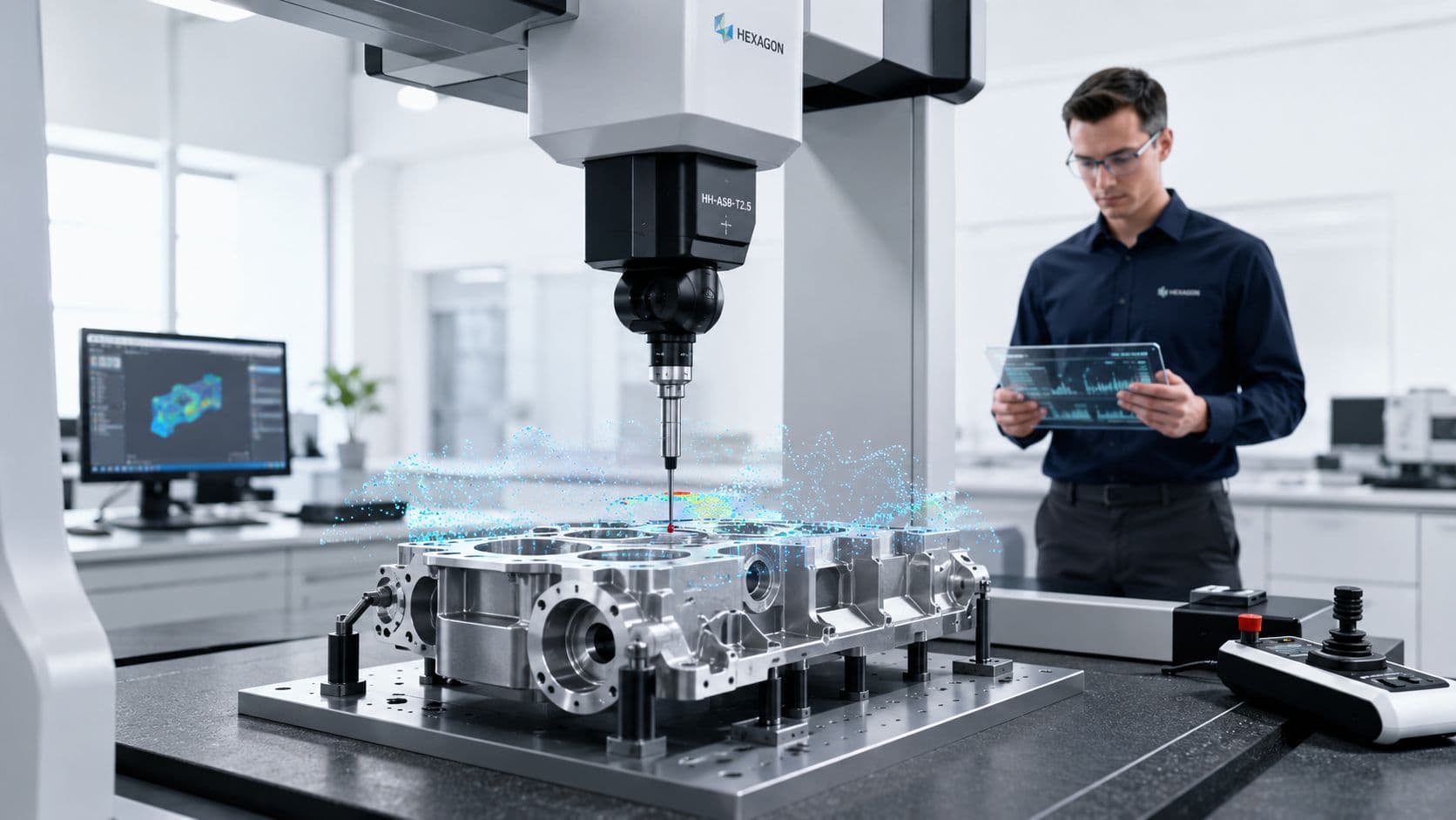
A Coordinate Measuring Machine, or CMM, measures the physical geometry of a part in three dimensions. It does that by recording X, Y, and Z locations from a probe, then comparing those measured points to the drawing or CAD model.
Think of it as a 3D caliper with memory
The simplest analogy is a super-powered digital caliper that doesn't just give you one reading. It builds a spatial map of the part.

A touch probe can contact selected features such as holes, planes, bosses, and edges. A scanning system can gather many more points over a surface. Software then aligns the measured geometry to the intended datum structure and evaluates whether the part conforms to the print.
That's what makes CMM inspection different from isolated gauge checks. You're not just measuring dimensions one by one. You're measuring relationships between features in a controlled coordinate frame. If you want a broader grounding in how this fits into inspection planning, this practical guide to dimensional inspection for engineers is a useful companion.
Why engineers rely on it
CMM inspection is critical because modern parts don't fail in obvious ways. They fail in geometry. A mounting face can be slightly off orientation. A hole pattern can be shifted relative to datums. A contoured part can match a few spot checks and still miss the intended profile.
The business side reflects that importance. The global CMM Inspection Service Market was valued at $2,397.5 million in 2024 and is projected to reach $4,500 million by 2035, with a projected 5.9% CAGR from 2026 to 2035, according to Wise Guy Reports' CMM inspection service market summary. That growth tracks with one reality on the shop floor: as parts get more complex, manual verification stops being enough.
A practical way to think about CMM inspection services is this:
- For design engineers: they confirm whether the manufactured part matches design intent.
- For manufacturing engineers: they separate process variation from setup mistakes and drawing interpretation errors.
- For sourcing teams: they provide traceable evidence when a supplier says a part is in tolerance.
Practical rule: If the cost of being wrong is higher than the cost of measuring correctly, send the part to CMM.
That's especially true in prototyping, where one wrong conclusion can send the next design iteration in the wrong direction.
CMM Technology Deep Dive Touch-Trigger vs Scanning
Not all CMM programs collect data the same way. The biggest practical split is between touch-trigger probing and scanning. If you choose the wrong method, you either pay for unnecessary data or miss the information you needed.

Touch-trigger when feature certainty matters most
A touch-trigger probe measures discrete points. The stylus contacts the part at one location, records the coordinate, retracts, and repeats. This works very well when you care about clearly defined features such as:
- Hole location
- Bore diameter
- Plane orientation
- Boss size
- Datum construction
For first articles on machined parts, touch-trigger often gives the cleanest answer to a specific question. Is the hole where the drawing says it should be? Is this face perpendicular to the datum? Is the slot width acceptable?
Its weakness is coverage. If you only sample a few points on a complex surface, you may miss shape variation between those points. That's like checking a road by touching a few spots with a ruler instead of driving the full length.
Scanning when surface behavior matters
Scanning collects continuous or high-density point data across a path or surface. That makes it useful for freeform geometry, contoured faces, blended transitions, and surfaces where local deviations matter.
This is especially relevant for additive parts, sculpted housings, formed components, and low-volume parts with surfaces that don't reduce nicely to a handful of basic features. The qualitative trade-off is simple. Scanning gives you more shape information, but it can also generate more data than you need if your actual concern is a small set of critical dimensions.
An underserved but important decision point is the overlap between CMM and 3D scanning. According to Nel Pretech's discussion of CMM inspection services, only 12–15% of inspection service listings explicitly compare CMM and scanning on cost or lead time, even though demand for hybrid inspection in additive manufacturing has increased 28% year over year. That gap shows up in real projects. Engineers often know they need “inspection,” but not which inspection strategy gets the answer fastest.
If you need to certify a few critical features, dense surface data can slow you down. If you need to understand a full organic surface, sparse point checks can mislead you.
Touch-Trigger vs. Scanning Probes at a Glance
| Attribute | Touch-Trigger Probes | Scanning Probes |
|---|---|---|
| Data collection style | Discrete points | Continuous or dense point collection |
| Best for | Holes, planes, slots, datums, basic GD&T checks | Freeform surfaces, profiles, contoured geometry |
| Speed | Efficient for limited feature sets | Efficient when full-surface information is needed |
| Data density | Low to moderate | High |
| Typical reporting strength | Feature-level conformance | Surface behavior and profile understanding |
| Main risk | Missing local variation between points | Producing more data than the decision requires |
| Good fit in prototyping | First articles with defined CTQs | Shape validation, reverse engineering, additive parts |
For many low-volume programs, the best answer isn't one or the other. It's touch-trigger on the critical datums and assembly features, plus scanning where the surface itself drives function.
Decoding CMM Deliverables Reports FAI and PPAP
A CMM service isn't just machine time. Its key output is the documentation that lets engineering, quality, and suppliers make decisions from the same evidence.
What a standard report should tell you
The base deliverable is usually a dimensional inspection report. At minimum, it should compare the nominal requirement on the drawing to the actual measured result, show the allowed tolerance, and indicate whether the feature passed.

Good reports are easy to audit. You should be able to trace each line item back to a ballooned drawing, where every measured feature has a numbered callout. Without that drawing, long reports become a spreadsheet puzzle.
What to look for in practice:
- Feature traceability: Each measured result should map back to one drawing requirement.
- Clear datum alignment: The report should reflect the datum strategy that matches the print, not an arbitrary setup.
- Usable out-of-tolerance detail: A fail should show enough context to support correction, not just a red box.
If your project requires a more formal package, this guide to first article inspection is worth reviewing alongside the CMM report itself.
Where FAI and PPAP fit
A First Article Inspection, or FAI, is the structured verification of a new part, revised part, or new process output before broader production moves ahead. The point of FAI isn't paperwork for its own sake. It's to confirm that the manufacturing process can make the part to drawing.
A PPAP, or Production Part Approval Process, goes further. It's a production approval package typically associated with automotive-style control and supplier qualification. The CMM report is often one element inside that package, alongside other records tied to process validation and release.
Here's the practical distinction:
- Use an FAI when you need confidence in a first-off part, prototype, or new setup.
- Use a PPAP package when the customer or industry requires formal production approval and process evidence.
A CMM report tells you what the part is. An FAI tells you whether the first part is acceptable for release. A PPAP supports the bigger claim that the production process is ready.
Teams get into trouble when they ask for “a CMM report” but really need a first article package, or when they order a full PPAP-level deliverable for an early prototype that only needed focused dimensional evidence.
The Language of Precision GD&T and ISO Standards
A CMM becomes highly valuable when the drawing uses GD&T, not just plus-minus dimensions. That's where inspection shifts from simple size checks to validating design intent.
Why GD&T is where CMM becomes useful
CMM inspection quantifies geometric dimensions by sampling X, Y, and Z coordinates and evaluating compliance with ASME Y14.5 GD&T standards for form, orientation, location, and runout, as described in 3D Engineering's dimensional CMM inspection overview. The same source notes that industry-standard calibration follows ISO 10360, and that traceable metrology supports applications where tolerances often reach ±0.005 mm or tighter.
That matters because many critical requirements aren't “make this feature 10 mm wide.” They're more like “locate this hole pattern relative to these datums so the assembly works every time.”
Take true position as a practical example. A caliper can measure hole diameter. It can't reliably tell you whether the hole axis is correctly located relative to a datum reference frame built from multiple surfaces. A CMM can. It constructs the datums, calculates the feature center or axis, and evaluates the deviation in the language the drawing uses.
Some of the most common callouts that justify CMM inspection services are:
- Flatness: Important for sealing faces and mounting surfaces.
- Perpendicularity and parallelism: Critical for stack-up control and guided motion.
- True position: Often the primary driver for hole patterns and mating parts.
- Profile: Essential for cast, molded, additive, and freeform machined surfaces.
- Runout: Relevant when rotating features must stay controlled in use.
For engineers who need a tighter working grasp of the drawing side, this practical guide to geometric dimensioning and tolerancing is a useful reference.
Why ISO 10360 matters to the result
The part isn't the only thing being judged. The CMM itself has to be trustworthy.
If probe calibration is off or fixturing is poor, measurement uncertainty increases and the report can become misleading. The same 3D Engineering source explains the cause-and-effect directly: insufficient calibration or improper setup can create false conformance or false rejection. It even notes that a misaligned datum setup can cause positional errors exceeding 0.01 mm in multi-axis CNC-machined components.
That's why experienced engineers care about fixture strategy and alignment method, not just machine brand. A well-calibrated CMM used with the wrong datum interpretation can still answer the wrong question with great precision.
Good metrology doesn't just measure a part accurately. It measures the part the same way the drawing intends it to be manufactured and assembled.
How to Get the Best Results from Your CMM Service
Most problems with CMM inspection services start before the part reaches the machine. The report usually reflects the quality of the inputs, the clarity of the scope, and the realism of the measurement plan.

What to send before inspection starts
If you want useful results fast, send a complete package. That usually means the latest drawing revision, the CAD model, material or process context if it affects fixturing, and a clear note on which features are critical to quality.
The best requests also identify what decision the inspection needs to support. Are you approving a first article? Troubleshooting a fit issue? Comparing machined geometry to an additive prototype? The answer changes the inspection strategy.
A practical checklist:
- Send clean CAD data: STEP is usually the safest neutral format for measurement programming.
- Mark the true CTQs: Don't ask for every possible feature if only a few dimensions determine fit or function.
- Define datum intent clearly: If the print leaves room for interpretation, talk through the setup before measurement begins.
- Flag fragile parts or soft materials: Fixturing can distort the part before the machine ever takes a point.
- State the report format upfront: A short capability check, full balloon report, FAI, and PPAP-style package are not the same deliverable.
How to choose the right inspection partner
The right provider isn't just the lab with the nicest machine photo. You want a team that understands your part family, your tolerancing style, and your industry's documentation expectations.
Market leadership in CMM hardware gives some context here. Hexagon, Zeiss, Mitutoyo, and Nikon collectively command over 60% of total global revenue in the CMM market, and the broader CMM equipment market was estimated at $3.20 billion in 2023 and projected to reach $5.68 billion by 2030, with a projected 8.7% CAGR from 2024 to 2030, according to this CMM market analysis on LinkedIn. In practice, those brands matter because reliability, calibration behavior, software integration, and probe ecosystem all affect measurement quality.
Still, machine brand alone won't save a weak inspection plan. Ask questions such as:
- What industries do they support regularly? Aerospace, automotive, medical, and general industrial work don't all use the same reporting habits.
- Can they inspect to your drawing logic? This is especially important when GD&T is dense or the datum scheme is assembly-driven.
- Will they review the scope before quoting? Good providers push back when the requested report is excessive or incomplete.
When to choose CMM, 3D scanning, or both
For prototyping and low-volume production, the choice usually comes down to the decision you need to make.
Choose CMM-first when:
- You need hard answers on critical dimensions and GD&T.
- The part has defined datums and a manageable feature set.
- Release risk is tied to a few high-consequence measurements.
Choose 3D scanning-first when:
- You need fast surface visibility on complex geometry.
- The part is organic, freeform, or additive in a way that makes sparse point checks incomplete.
- You're diagnosing shape drift more than certifying a print.
Choose a hybrid approach when:
- The part includes both precision interfaces and complex surfaces.
- You need speed in early prototype learning, but also traceable measurements on final decision points.
- You want broad shape feedback without losing confidence in datums, hole patterns, or mating features.
Imagine a vehicle inspection. A 3D scan is the aerial map. A CMM is the survey stake driven into the ground at the exact legal boundary. For many prototype programs, you need both perspectives to move quickly without making bad release calls.
CMM Inspection A Strategic Tool for Modern Manufacturing
The biggest mistake teams make is treating CMM inspection as a pass-fail tax at the end of manufacturing. It's more useful than that.
Done well, CMM inspection services give design engineers feedback on whether the model matches real process capability. They give manufacturing engineers clues about fixture behavior, tool wear, and setup bias. They give sourcing and quality teams a defensible basis for accepting parts, rejecting them, or asking the right questions before the next build.
That's why the service matters so much in prototyping and low-volume production. At that stage, the job isn't only to catch bad parts. It's to learn quickly which dimensions are stable, which surfaces are drifting, and which tolerances are driving cost without protecting function.
If the part has a few high-risk features and clear datums, go CMM-first. If the geometry is complex and the goal is shape insight, start with scanning. If the project mixes both realities, use a hybrid plan and be deliberate about which tool answers which question.
The teams that move fastest aren't the ones that inspect the least. They're the ones that inspect with purpose, then use the data to make fewer wrong decisions.
If you need a manufacturing partner that can support prototypes through low-volume production with documented inspection, FIRMFG offers CNC machining, additive, molding, and quality support built for engineering teams that need both speed and reliable dimensional feedback.