Surface Texture Callout: A Guide for Engineers
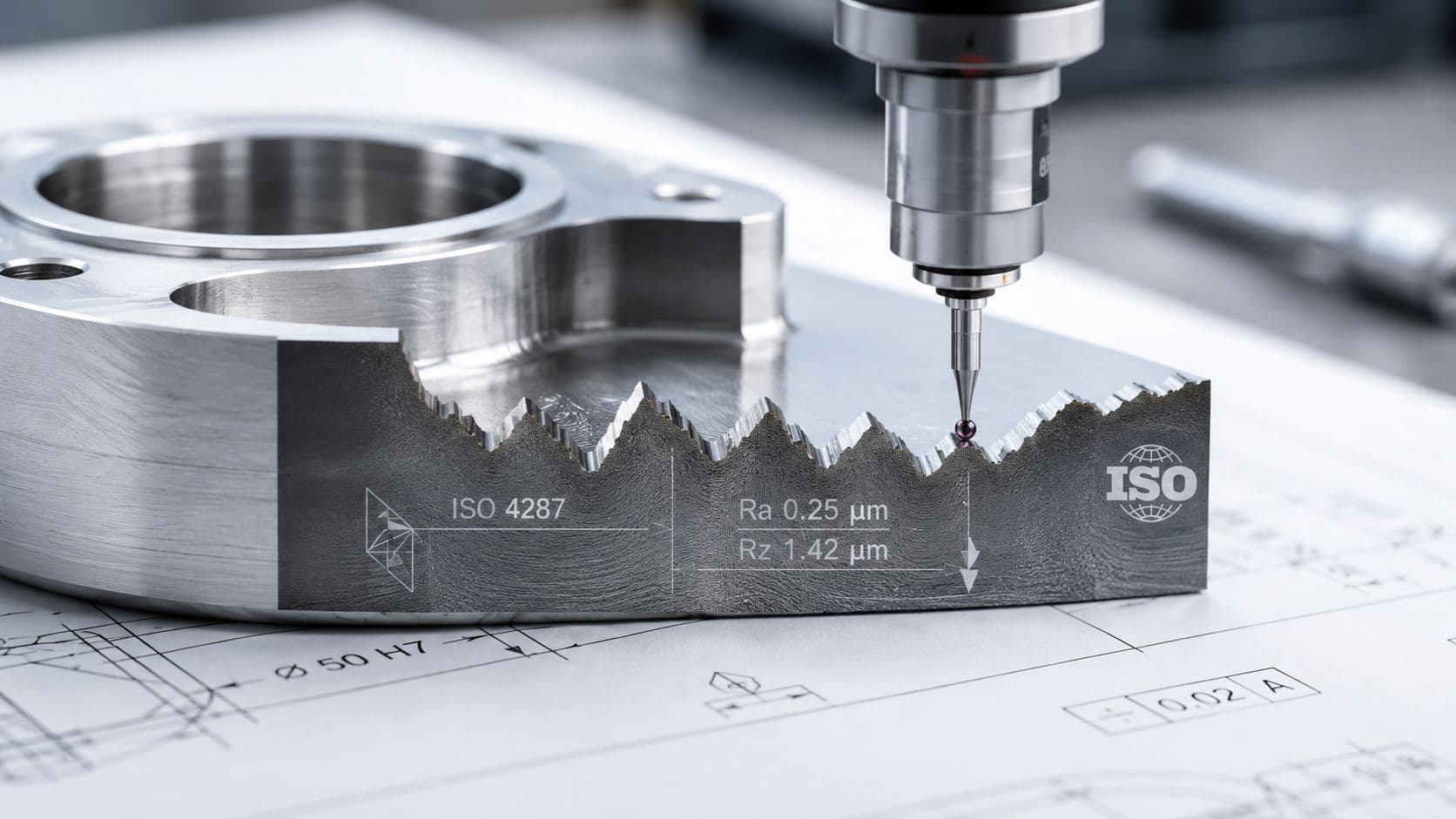
You're probably looking at a drawing right now with a surface finish note that seemed harmless when it was added. Then the quotes came back high, the supplier asked whether you meant Ra or Rz, or a test part fit fine but leaked in validation. That's the moment surface texture stops being a drafting formality and starts acting like what it really is: a functional requirement.
Most drawing mistakes around surface finish aren't about choosing a number that's wildly wrong. They come from choosing the wrong parameter for the job, or applying a machining-style callout to a process that creates texture in a completely different way. A face seal, bearing seat, molded cosmetic surface, and printed prototype can all look “smooth” to the eye while behaving very differently in service.
Table of Contents
- Why Your Surface Texture Callout is Critical
- Decoding the Surface Texture Symbol
What the symbol communicates
Why Ra and Rz are not interchangeable
ISO vs ASME Standards for Surface Finish- What stays consistent across borders
Applying Callouts in CNC Machining 3D Printing and Molding- CNC parts need parameter choices that match the surface function
- 3D printed parts need the callout tied to build condition
- Molded parts need callouts that reflect tool and resin behavior
Measurement Inspection and Tolerance- A drawing note is only as good as the inspection plan
DFM for Surface Finish Balancing Cost and Function- Cost increases usually come from process changes
- Choose the parameter before you tighten the value
- Match the callout to what the process naturally makes
- A few DFM rules prevent expensive surface finish mistakes
Conclusion Your Blueprint for Perfect Finishes
Why Your Surface Texture Callout is Critical
A part can be dimensionally perfect and still fail because the surface did the wrong thing.
That usually shows up at interfaces. A gasketed face leaks. A sliding component scuffs early. A cosmetic panel passes incoming inspection but shows machining marks in final assembly lighting. In each case, the drawing may have had a finish note, but the note didn't fully express the functional intent.
A surface texture callout is the language that connects design intent to manufacturing reality. It tells the machinist, mold maker, printer, and inspector what matters on that surface and what doesn't. If that language is vague, every downstream team fills in the blanks differently.
Practical rule: If a surface has a job beyond “exist,” it deserves an intentional callout.
The biggest mistake is treating surface finish as a cosmetic control only. For non-critical faces, that's often fine. But on sealing lands, contact tracks, bearing seats, optical-adjacent surfaces, or any feature that carries load through a small contact area, microscopic peaks and valleys change performance. The average roughness might look acceptable while the peak structure still causes leakage, wear, or local damage.
That's why the parameter matters as much as the value. Designers often default to Ra because it's familiar and easy to place on a print. But Ra is an average. Averages hide extremes. If your failure mode depends on isolated peaks, grooves, or tool marks, a single Ra value can approve the wrong surface.
A good callout does three things:
- Defines function clearly so the shop knows whether the surface must seal, slide, bond, or look clean.
- Matches the process so the requirement can be achieved by milling, turning, grinding, molding, or printing without unnecessary rework.
- Supports inspection so quality can verify the surface in a repeatable way.
When those three stay aligned, you avoid expensive arguments after the parts are already built.
Decoding the Surface Texture Symbol
A supplier can hit Ra 3.2 and still ship a surface that leaks, wears early, or prints a witness line into a molded part. That usually happens because the drawing specified a value, but not the right parameter for the job.

What the symbol communicates
The surface texture symbol is compact, but it can carry several different instructions at once. Under ISO-style notation, the callout may define the roughness parameter, limit or range, lay direction, sampling information, manufacturing method constraints, and machining allowance, as described in this DIN ISO 1302 overview.
The part many teams recognize first is the roughness requirement itself. A callout such as Ra 3.2 is often read as a standard machined finish, and on many drawings that is exactly how it gets treated on the shop floor.
That is where drawings fail, especially on surfaces with a defined function.
A full symbol may also include:
- Lay direction such as M, C, or X, which indicates the dominant texture pattern left by the process
- Sampling length or evaluation conditions, which affect how the surface is measured and whether results are repeatable
- Process restrictions, which tell the supplier whether material removal is required or prohibited
- Allowance or added controls, used when stock removal or secondary finishing must be planned up front
For a practical comparison of common finish ranges and how shops interpret them by process, this surface roughness chart for CNC machining and finish selection is a useful reference during drawing review.
Why Ra and Rz are not interchangeable
Ra is an average. Rz pays more attention to peak-to-valley extremes. That difference sounds small on paper and becomes expensive in production.
Use Ra where the average texture level is what matters. Typical examples are cosmetic faces, general brackets, and non-mating machined walls. Use Rz where isolated grooves, torn material, or tall peaks can break function. Sealing lands, sliding tracks, press-contact zones, and surfaces that must control tool-mark depth are common cases. This discussion of specifying surface texture beyond Ra explains that distinction well.
A CNC milled face with a stable cutter can produce a clean Ra value while still leaving directional valleys that matter for sealing. An injection molded face can look smooth overall but carry peak structure from the mold surface or flow behavior that shows up better under a parameter other than Ra. A 3D printed surface is even less forgiving. Layer lines and partially fused edges often make a simple average roughness number a poor description of actual function.
A sealing surface responds to the highest peaks, deepest valleys, and texture direction along the leak path. Ra alone may not control any of those well enough.
A rough conversion between Ra and Rz is sometimes used in informal discussion. It should not be used as a design rule. If function depends on local extremes, specify the parameter that measures those extremes instead of back-calculating from Ra and hoping the process behaves.
Use this decision check:
| Surface condition | Better primary control |
|---|---|
| Cosmetic face, non-mating wall, general bracket | Ra |
| Seal land, sliding contact, localized damage risk | Rz, often with Ra as secondary context |
| Texture direction affects leakage or wear | Lay plus the appropriate roughness parameter |
The practical mistake is not choosing a roughness value that is too high or too low. It is choosing a parameter that does not match the failure mode. That is how a print can pass inspection and still fail in service.
ISO vs ASME Standards for Surface Finish
A drawing leaves your office with Ra 1.6 on a sealing face. The supplier in another region machines it, the inspector signs off, and the part still leaks in assembly. In many cases, the failure is not the number. It is the standard behind the symbol, the parameter chosen, or the missing rules for how that parameter is measured.

What stays consistent across borders
ISO and ASME are close enough that experienced shops usually recognize the symbol and the basic intent. A callout for Ra still points to average roughness. Surface texture is still treated as a measurable requirement on the drawing. If the drawing package is disciplined, global suppliers can work from it without much drama.
The trap is assuming that similar symbols mean identical practice in the shop and inspection room. They do not always. ISO 1302 focuses on how the requirement is shown on the drawing. ASME B46.1 is heavily tied to terminology, parameters, and measurement conventions. ASME Y14.36 covers how surface texture symbols are applied in engineering drawings. That split matters when a team copies symbol habits from one system and inspection habits from another.
Where the real mistakes happen
Parameter choice is one of the biggest misses.
A print may use Ra because it is familiar, easy to find on comparator charts, and available on nearly every profilometer. That works for many general machined surfaces. It is a weak choice for every function. If the surface has to seal, retain lubricant, resist peak-driven wear, or control contact stress, Rz may describe the risk better than Ra. The standard may tell you how to present the callout, but it does not rescue a poor parameter choice.
That gap shows up in production:
- CNC machining often produces directional tool marks. A part can meet an Ra limit and still have valley structure that matters for sealing or sliding contact.
- Molding can replicate mold texture well, but flow behavior, tool polish, and part geometry can leave local features that Ra averages out.
- 3D printing creates stepped surfaces and partially fused edges. Average roughness alone often hides the peaks and valleys that drive fit, friction, or post-processing effort.
The cost impact is real. A supplier who sees only a tight Ra requirement may add grinding, polishing, or secondary finishing to every part, even when the function only needed control of peak height on one face. The opposite mistake is cheaper up front and expensive later. A part passes incoming inspection, then fails in service because the drawing controlled the wrong surface parameter.
How to keep ISO and ASME from getting mixed
State the governing drawing standard in the title block or notes. Keep the symbol style consistent with that standard. Then specify the surface parameter that matches the failure mode.
Common sources of confusion include:
- ISO-style symbols with ASME-style interpretation, especially on supplier-marked prints and inherited templates
- Missing measurement context, such as cutoff or evaluation rules when the surface is function-critical
- Unit inconsistency across a drawing package shared between metric and inch-based teams
- Ra-only callouts on surfaces where lay, waviness, or peak-to-valley behavior affects performance
I usually ask one question during design review: What would make this surface fail in the field? If the answer is leakage, scuffing, high contact stress, or coating adhesion, that answer should drive the parameter selection before anyone argues about the exact value.
Standardize the symbol, but also standardize the interpretation, parameter, and inspection method.
That is the practical difference between a drawing that travels well and one that creates scrap, delays, and arguments across suppliers.
Applying Callouts in CNC Machining 3D Printing and Molding
A drawing gets released with a clean-looking surface callout on every visible face. The machine shop prices in extra passes, the molder pushes back because the note does not match mold texture practice, and the printed prototype arrives looking “wrong” even though it matches the process. The problem usually is not the number alone. It is the wrong parameter for the process and the job the surface has to do.

CNC parts need parameter choices that match the surface function
CNC machining gives designers the most freedom, which is why it also creates the most over-specified drawings. Shops can improve finish with tool selection, step-over, feed, speed, and secondary operations, but every step costs time. The expensive mistake is asking for a low Ra on surfaces that only need to clear, clamp, or look acceptable after coating.
Parameter choice matters as much as the target value. Ra works well for general machined faces where average roughness is a reasonable proxy for performance. It is often enough for bracket faces, covers, and non-sliding exterior surfaces. A seal land, bearing seat, or loaded contact band is different. Those surfaces often fail because of peak height, local damage initiation, or lubricant behavior. In those cases, an Rz-based requirement may describe the risk better than Ra, even if two surfaces show similar average roughness.
That distinction changes process planning. A shop can sometimes hit an average Ra target with a process that still leaves occasional taller peaks. If the part cares about leakage, wear-in, or coating thin spots, those peaks are the problem. Calling out Ra alone can approve a surface that functions poorly, while calling out Rz on a non-critical face can force unnecessary finishing.
Use a narrow callout strategy for CNC parts:
- Apply finish requirements only to functional surfaces.
- Use Ra for general-purpose machined faces where average texture is what matters.
- Use Rz or a more specific requirement when peak-to-valley behavior affects sealing, contact stress, or wear.
- State if grinding, honing, polishing, or another secondary operation is acceptable, because that decision drives cost and lead time.
3D printed parts need the callout tied to build condition
Additive processes break the habit of treating surface texture as a simple machining note. Layer lines, stair stepping, support scars, bead shape, and print orientation dominate the surface. A printed part can meet the design intent and still look nothing like a machined surface.
Parameter selection gets practical. Ra can still be measured on a printed surface, but it often misses the feature that users or mating parts care about. A printed housing may be acceptable with visible texture if the inside locators fit and the cover seals after post-processing. A medical handle may care more about tactile consistency. A printed airflow path may care about larger surface features that affect flow more than average line roughness. If the drawing says only “Ra X” and does not state as-printed versus post-processed condition, the supplier has to decide whether sanding, tumbling, vapor smoothing, or coating is allowed.
Write the requirement around the state of the part:
- Identify the required surface as as-built or post-processed.
- Limit the callout to the surfaces that interact with mating parts, users, or flow paths.
- Choose a parameter that reflects the actual failure mode, not the one most familiar from CNC drawings.
Molded parts need callouts that reflect tool and resin behavior
Molded surfaces come from the tool, but the final result also depends on resin shrinkage, fill behavior, venting, draft, and ejection. A generic machined-style roughness note often creates confusion because it ignores how molded texture is produced and controlled.
On molded parts, the design question is usually more specific. Does the surface need gloss control, grip, light diffusion, paint adhesion, reduced drag marks, or easy release from the tool? Those are different requirements, and they do not all map cleanly to Ra. In practice, molded cosmetic surfaces are often better controlled with mold texture standards or approved appearance samples, while functional sealing or sliding areas may still need a measurable roughness requirement.
Rz can be the better choice on molded sealing features if isolated peaks matter. Ra can be adequate on less sensitive faces where the average finish tracks the intended result closely enough. The wrong choice can send the toolmaker in the wrong direction. Chasing a tighter Ra on a cosmetic face may add polishing cost without improving appearance consistency. Ignoring peak behavior on a shutoff or sealing feature can create flash, leakage, or premature wear.
A few habits prevent trouble:
- For CNC, call out the minimum number of surfaces and match Ra or Rz to the failure mode.
- For 3D printing, define the surface condition before anyone interprets the number.
- For molding, use texture standards or appearance criteria for cosmetic faces, and measurable roughness only where function requires it.
If the team is also defining how these surfaces will be checked in production, this practical guide to dimensional inspection for engineers helps connect drawing notes to a usable inspection plan.
Measurement Inspection and Tolerance
A drawing note has no teeth until someone can verify it repeatably on a real part.
A drawing note is only as good as the inspection plan
Surface texture is commonly checked with a contact profilometer or a non-contact optical system. Both can be valid, but they don't look at the surface the same way. A stylus traces a line profile across the part. Optical systems evaluate the surface differently and can respond in their own way to reflective materials, steep local geometry, and directionality.
That's why inspection has to be part of the specification conversation, not a cleanup task after release. If design expects one type of result and quality uses another method without alignment, you get parts that “pass” one system and fail another discussion.
A useful cross-check during release is to ask:
- What instrument will be used in production or incoming inspection?
- Where will the trace be taken on the feature?
- In what direction relative to lay or machining marks?
- What filtering or evaluation settings are assumed by the lab?
For teams building broader inspection discipline around texture and geometry, this practical guide to dimensional inspection for engineers gives good context for turning print requirements into usable quality plans.
Inspection arguments usually start long before the first measurement. They start when the drawing leaves out how the result should be judged.
Sampling length and acceptance need agreement
Sampling length sounds like a lab detail, but it affects what value gets reported. If the callout includes sampling length, that tells the inspector how much of the surface to evaluate. If it doesn't, different default assumptions may lead to different results even on the same part.
Tolerance interpretation matters too. Surface finish isn't like checking a simple linear dimension with one caliper reading. Local variation is normal. Tool entry, exit, edge conditions, fixturing marks, and process transitions can all create texture differences across one face.
Good practice is to define acceptance around the functional zone, not around a random convenient spot. On a sealing face, inspect the actual seal path. On a cosmetic panel, inspect where the user will see reflected light. On a wear track, inspect where contact occurs.
When engineers and inspectors agree on location, direction, and method before the first article arrives, most finish disputes disappear.
DFM for Surface Finish Balancing Cost and Function
A drawing calls out Ra 0.4 on every machined face. Purchasing gets quotes back at twice the expected cost, the machinist asks whether grinding is required, and no one can explain why a bracket sidewall needs the same finish as a sealing land. That is a parameter problem as much as a value problem.
The cheapest surface is the one you did not over-specify. The most expensive mistake is tightening the wrong requirement on the wrong face, then discovering late that the functional surface needed a different parameter entirely.

Cost increases usually come from process changes
On many CNC parts, a standard machined finish is routine. Cost rises fast when the callout pushes the shop out of that normal cutting window and into slower feeds, extra passes, tighter tool control, or a secondary operation such as grinding, honing, or lapping. Engineers often focus on the roughness number. Suppliers price the process needed to hit it.
That difference matters on real parts. A milled housing wall with a modest Ra callout may run in the main machining cycle. A shaft seat with a much finer requirement may need grinding. A valve bore may not care about average roughness alone at all. It may fail because peak-to-valley behavior is wrong, which is where Rz can be more useful than Ra.
That is the point many drawings miss.
Choose the parameter before you tighten the value
Ra works well for general machining quality and many cosmetic or non-critical surfaces because it averages the profile. That averaging can hide isolated peaks and valleys. For parts where leakage, wear initiation, coating holdout, or localized contact matter, Rz often gives a better warning of what the surface will do in service.
Use that logic by process, not just by print habit:
- CNC machining: Use Ra for most general faces, mounting pads, and non-mating features. Switch to Rz or add lay control where sealing, sliding contact, or fatigue sensitivity depends on local profile shape.
- Molding: Surface texture is often driven by tool polish, EDM texture, or intentional grain. A low Ra callout on the part does not tell the toolmaker enough if appearance, release, or paint adhesion is the actual concern.
- 3D printing: Printed surfaces are usually anisotropic and process-dependent. A single Ra value can be misleading if stair-stepping, bead shape, or layer orientation drives function more than average roughness does.
A rough rule I use with design teams is simple. If the surface only needs to look or machine "reasonably clean," start with Ra. If the surface has to seal, slide, carry concentrated load, or survive thin-film contact, check whether Ra is even the right parameter.
Match the callout to what the process naturally makes
This table is a starting point for design reviews, not a substitute for supplier capability data.
| Process | Typical shop-floor use of finish callout | Where cost usually jumps | Parameter risk |
|---|---|---|---|
| CNC machining | General faces often called out in Ra | Below the normal machined finish, or when secondary finishing is implied | Ra can miss damaging peaks on contact or seal surfaces |
| Grinding | Used for tighter geometry and finer functional surfaces | Setup, stock allowance, and added operation time | A fine Ra alone may not describe load-bearing behavior |
| Lapping or honing | Used on high-performance bores and seats | Process time and inspection burden | Wrong if the callout ignores directionality or localized defects |
| Molding | Tool finish transfers to the part to varying degrees | High-polish tools, texturing, and mold maintenance | Numeric roughness alone may not control appearance or release |
| 3D printing | As-printed surfaces vary strongly by orientation and process | Post-processing, machining, or sealing steps | Ra often hides layer-driven texture behavior |
For the broader review habits behind these decisions, use a design for manufacturability approach that ties drawing requirements to process capability.
A few DFM rules prevent expensive surface finish mistakes
- Put specific finish callouts only on surfaces with a defined function.
- Keep non-critical surfaces as coarse as the assembly, appearance, and downstream process will allow.
- Call out Rz when local peaks and valleys matter more than the average profile.
- Do not imply grinding, polishing, or lapping by accident. If the requirement effectively demands a secondary process, expect quote impact and longer routing.
- Separate cosmetic intent from functional intent. A polished-looking surface can still perform poorly in sealing or wear.
- Review molded and printed parts differently from machined parts. Their texture comes from entirely different process physics.
One more practical point. Blanket finish notes are where cost spreads subtly across the whole part. A targeted callout on the sealing face, bearing seat, or cosmetic Class A area is usually better engineering and better purchasing.
Fine finish is a tool, not a quality plan. Use the parameter that matches the failure mode, then set the loosest value that still lets the part do its job.
Conclusion Your Blueprint for Perfect Finishes
A solid surface texture callout does more than decorate a drawing. It tells manufacturing what the surface must do, tells quality how to verify it, and tells sourcing where cost will appear.
The key habit is simple. Stop asking only, “What Ra value should I put on this face?” Ask, “What failure mode am I trying to prevent?” If the answer involves general appearance or non-critical machining quality, Ra is often enough. If the answer involves sealing, localized contact, or tool-mark sensitivity, the parameter itself may need to change. That's where Rz, lay direction, and inspection method stop being optional details.
Before sign-off, run a short checklist:
- Is the surface function defined?
- Is Ra the right parameter, or does the surface need Rz or directional control?
- Does the chosen process naturally support that callout?
- Will inspection measure the same thing design intended?
- Is the requirement as coarse as possible without compromising performance?
Engineers who get this right don't just release cleaner drawings. They release parts that work the first time, quote more realistically, and cause fewer supplier disputes.
If you need a manufacturing partner that can build prototypes and production parts while working from clear surface finish and inspection requirements, FIRMFG supports CNC machining, 3D printing, sheet metal fabrication, injection molding, vacuum casting, surface finishing, and documented quality inspection for metal and plastic components.