8 Rapid Prototyping Examples from Concept to Production
You've got the CAD approved, the team is aligned, and everyone wants parts on the bench by next week. That's usually the moment risk starts, not the moment it ends. A prototype that looks right can still hide assembly problems, false confidence in material behavior, or manufacturability issues that won't show up until tooling is already in motion.
Rapid prototyping works best when you stop treating it like a single process and start treating it like a decision sequence. The right prototype answers one specific question at a time. Can the housing survive handling? Does the light path work? Will this geometry machine cleanly? Can beta users interact with production-intent parts instead of stand-ins that distort feedback?
Across industries, rapid prototyping techniques have shown a 60% decrease in lead-time compared with traditional manufacturing methods, using approaches such as SLA, SLS, and FDM to avoid extensive tooling setup, according to ScienceDirect's overview of rapid prototyping. That speed matters, but only if the method matches the risk you're trying to remove.
Below are eight rapid prototyping examples that show how experienced teams make those calls. Each one focuses less on the prototype itself and more on why that process was chosen, what trade-offs came with it, and what usually separates a useful prototype from an expensive distraction.
Table of Contents
- 1. Example 1. Multi-Axis CNC Machining for a Medical Device Enclosure
Why CNC was the right call
What works in practice
2. Example 2. SLA 3D Printing for an Automotive Light Pipe- Why SLA fits this prototype better than other fast methods
3. Example 3. Rapid Injection Molding for a Consumer IoT Device- Why molded beta units matter
4. Example 4. Sheet Metal Fabrication for a Robotics Chassis- Why sheet metal wins for structural iteration
5. Example 5. Vacuum Casting for a Soft-Touch Overmold- Why vacuum casting fits ergonomic testing
6. Example 6. SLS 3D Printing for a Functional Drone Arm- Why SLS was the better structural prototype
7. Example 7. DFM-Led Redesign of an Aluminum Heat Sink- Why the first design failed the manufacturing test
8. Example 8. Iterative Sampling for a Medical Wearable- A staged prototype plan beats a hero prototype
Rapid Prototyping, 8-Case Comparison
From Prototype to Production. Making the Right Choice
1. Example 1. Multi-Axis CNC Machining for a Medical Device Enclosure
A medical team is three design reviews away from a pilot build, and the enclosure still looks fine in CAD. Then the first functional sample shows the actual problems. Screw bosses pull off-axis, the PCB sits on uneven standoffs, and the sealing face needs far more hand work than anyone expected.
That is why CNC machining earns its place early on enclosure programs that have to behave like real products, not visual models. For a handheld diagnostic device, the prototype has to answer more than “does the shape fit?” It has to show whether the housing can hold tolerance, assemble cleanly, survive handling, and support a finish that suits a clinical environment.

Why CNC was the right call
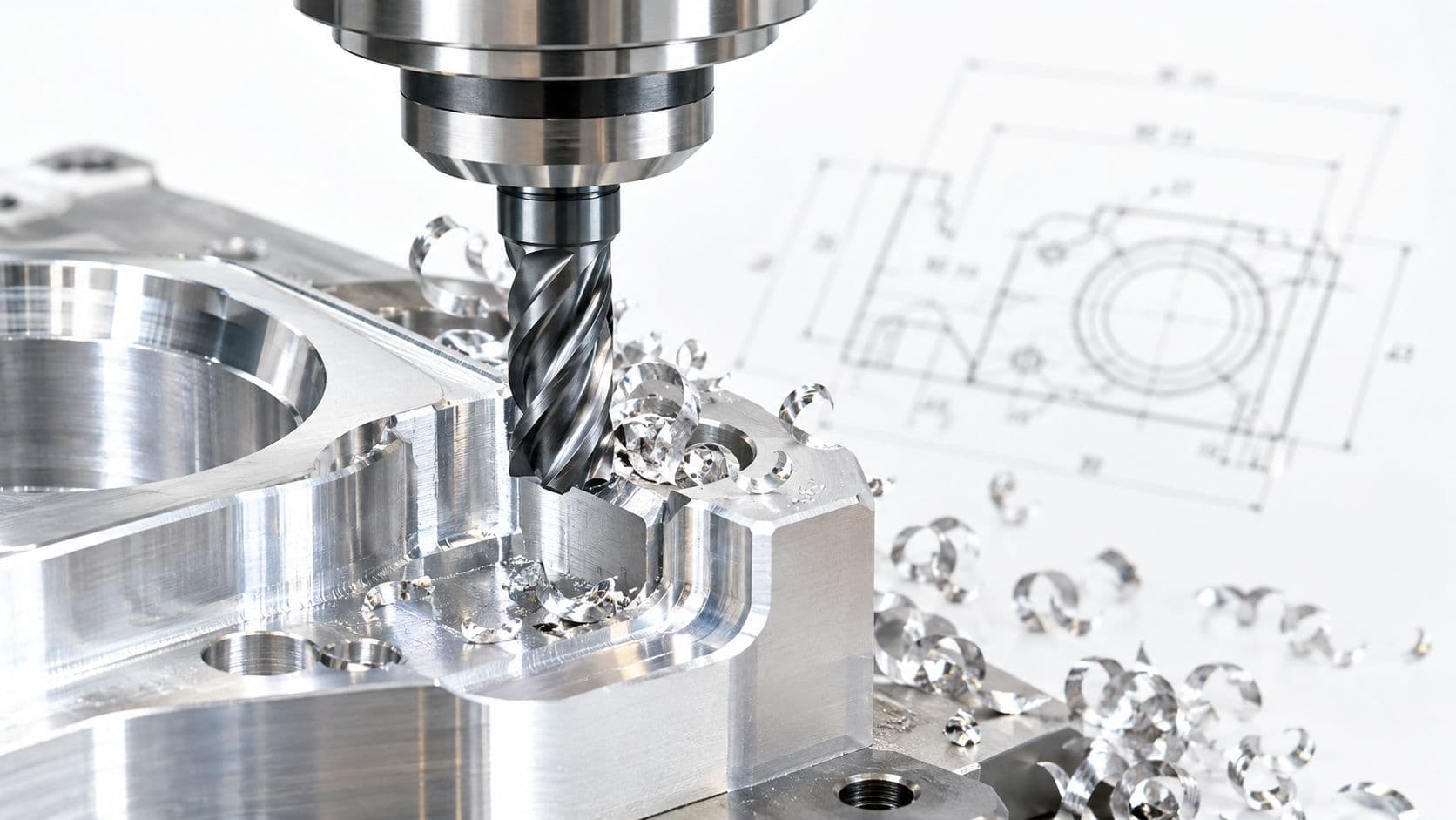
Multi-axis CNC is a good choice when geometry, material behavior, and assembly accuracy all matter at the same time. Printed parts can confirm general packaging, but they often mislead teams on thread strength, flatness, edge condition, and the way mating features behave after secondary finishing. Machined aluminum or engineering plastic gives a much closer read on production risk.
The trade-off is straightforward. CNC usually costs more per part than printed mockups and takes more planning up front. In return, teams get dense, stable parts with predictable mechanical behavior and much tighter control over datums, critical faces, and internal features. For regulated products, that trade often makes sense early because it exposes enclosure problems before they turn into tooling changes, validation delays, or assembly escapes.
Multi-axis capability matters when the enclosure includes intersecting internal features, side ports, recessed fastener access, or compound exterior surfaces. Shops can machine those details in fewer setups, which improves positional consistency and reduces the stack-up errors that show up when a housing has to close around electronics, seals, and user-facing components. Teams comparing setup count, access angles, and feature strategy should review where 5-axis CNC milling supports complex enclosure machining and where a simpler machining plan is the better cost decision.
What works in practice
Start by separating critical features from everything else. Mounting pads, connector locations, gasket lands, lens openings, and any face that controls assembly should carry the tightest tolerances. Outer cosmetic surfaces usually need good finish control, not aggressive dimensional control.
That distinction affects both quote quality and lead time.
A few design choices consistently reduce rework:
- Define functional datums from assembly intent: If the PCB, display, and connector stack all reference one side of the enclosure, the drawing should reflect that.
- Avoid machining complexity that does not change the decision: Deep pockets with tight internal corners, hidden cosmetic contours, and hard-to-reach side features can force extra setups without improving prototype learning.
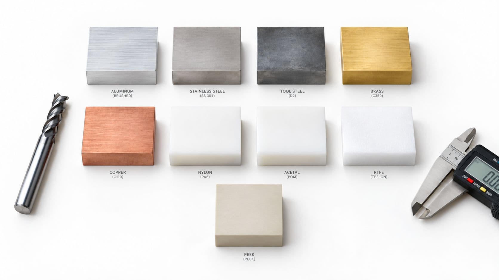
- Match the prototype material to the question being tested: Aluminum works well for stiffness, thread performance, and thermal behavior. Engineering plastics are often the better choice when latch behavior, weight, or electrical isolation matters more.
- Leave room for the next phase: If injection molding is the likely production path, use the CNC prototype to review wall transitions, draft strategy, fastener approach, and shutoff risk before tool design starts.
One practical rule saves a lot of waste. Tight-tolerance every feature only if every feature drives performance. Most enclosure prototypes do not need that, and shops will price the uncertainty accordingly.
Used well, CNC machining is not just a way to get a nicer prototype. It is a way to answer the expensive questions early: Will the enclosure assemble repeatably, will the critical geometry hold, and are you designing something that can move toward production without a major reset?
2. Example 2. SLA 3D Printing for an Automotive Light Pipe
A taillight program can stall on a small question. Does the light pipe carry output evenly across the feature, or will the final assembly show hot spots, shadowing, or stray glow at the edge? That is the kind of problem teams need to answer before they spend time and money on production tooling.
SLA is often the right prototype method for that stage because it gives a clear part with fine surface definition fast enough to support optical bench work, packaging checks, and design iteration in the same cycle. The value is not just speed. It is the ability to test optical geometry with a process that gets close enough in clarity and detail to expose real design issues early.
Why SLA fits this prototype better than other fast methods
For an automotive light pipe, the prototype has to answer a specific question. It needs to show how the geometry handles LED input, redirects light, and reveals defects caused by draft changes, rib placement, gate assumptions, or surface transitions. FDM usually leaves too much surface texture. SLS is useful for functional housings, but it is not the process for transparent optical evaluation. CNC can machine clear plastic, but cost and setup time climb quickly once the geometry includes small channels, blend surfaces, or complex mounting features.
SLA sits in the practical middle. It is fast, relatively affordable for iterative work, and capable of producing the clear features needed to judge whether the optical concept is worth carrying forward.
In a good prototype plan, teams use SLA to evaluate:
- Light uniformity: Whether the pipe distributes output consistently or creates visible bright and dark zones.
- Geometry sensitivity: Whether small changes in wall thickness, internal textures, or corner transitions create artifacts.
- Assembly fit: Whether the part still works once clips, LED boards, seals, and surrounding lenses are in place.
- Handoff risk: Which surfaces will later need tighter molding control, resin selection, or polishing standards once the design moves to injection molding with production thermoplastics.
The trade-offs teams need to respect
Clear SLA is useful, but it is easy to misuse.
The first trap is treating visual transparency as proof of production performance. SLA can show optical trends well enough for design decisions, but it does not replicate the exact refractive behavior, shrink profile, or long-term durability of an automotive molded resin. Engineers should use it to validate geometry direction, not to sign off final photometric performance.
The second trap is build setup. Orientation, support placement, and post-processing have a direct effect on what the team thinks it learned. Supports placed on optical faces leave witness marks. Heavy sanding can change light behavior. Aggressive polishing can hide a geometry problem that the molded part will still show later.
I have seen good CAD models produce bad conclusions because the print was prepped like a cosmetic demo part instead of an optical test article.
What good teams do differently
They separate optical surfaces from non-optical surfaces in the model and in the print brief. They call out which faces can accept supports, which faces can be polished, and which dimensions matter for alignment to the LED source. They also inspect the printed part instead of relying only on appearance. Visual realism is helpful, but dimensional verification is what keeps the prototype tied to the assembly condition it is supposed to represent. That gap between a convincing-looking part and a decision-ready part is discussed well in UX Pilot's analysis of rapid prototyping blind spots.
That is the strategic value of this example. SLA was not chosen because it is a popular 3D printing method. It was chosen because, at this stage, it gives the fastest useful read on optical geometry without paying for tooling too early. If the light path works, the team can move ahead with much better definition of which surfaces need true optical control and which ones are only cosmetic.
3. Example 3. Rapid Injection Molding for a Consumer IoT Device
A smart home sensor headed for beta launch usually needs more than prototype shells. Once electronics, snap fits, thermal behavior, battery access, and user handling all need validation at the same time, molded parts become far more useful than printed stand-ins.
That's the inflection point where rapid tooling earns its keep. You're no longer testing whether the industrial design is directionally right. You're testing whether real users can live with production-like parts before you scale.
Why molded beta units matter
For low-volume plastic parts, rapid prototype tooling can compress the path from CAD receipt to first-off sample delivery dramatically. In one documented case, a team delivered four tools, including two over-mold tools, within 14 days in Sydney, demonstrating how quickly tooling and initial sampling can move when the part strategy is set up correctly, according to W&S Plastics' rapid prototype tooling case study.
That's why this method fits beta hardware so well. A molded enclosure gives you wall sections, true draft, actual knit line risk, and production-like assembly feel that printed parts often hide.
Where rapid tooling pays off
The best use case is a design that's largely stabilized, but not so far along that you can't learn anything from a pilot run. For a consumer IoT device, molded beta units help teams validate:
- Snap features and assembly force: These are hard to trust in printed surrogates.
- Material-specific behavior: Flame-rated or impact-oriented resins behave differently from generic prototype materials.
- Certification readiness: Regulatory testing is more meaningful when the part construction matches actual production intent.
A moldflow review before tool cutting is usually money well spent. Weld lines, sink, and fill hesitation aren't theoretical problems once you're preparing a beta build. They're schedule problems.
If your team is lining up material and tool decisions, this overview of injection molding thermoplastics is a practical place to compare resin behavior and molding considerations.
One more trade-off matters here. Rapid molds are fast, but they also force discipline. If you're still moving bosses, changing battery doors, and debating PCB stack height, you probably aren't ready for tooling yet.
4. Example 4. Sheet Metal Fabrication for a Robotics Chassis
Robotics teams often over-machine frames that should have been bent sheet metal from day one. If the chassis needs stiffness, mounting accuracy, service access, and repeated layout changes, sheet metal usually gives a faster path to useful hardware than carving the whole thing from billet.
For an autonomous mobile robot, that matters because the enclosure is rarely just structure. It's also cable management, sensor alignment, battery packaging, airflow, and maintenance access.
Why sheet metal wins for structural iteration
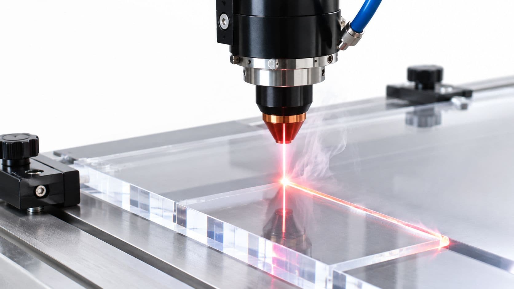
A bent aluminum chassis lets engineers change bracket locations, enlarge cable exits, and revise panel geometry without rebuilding the entire architecture. Laser cutting handles precise mounting patterns, and bending creates rigidity efficiently without asking the machine shop to remove a huge amount of material.
This method is especially effective when the team expects packaging to move. Motor controllers get swapped. Lidar placement changes. Battery retention gets revised after vibration testing. Sheet metal absorbs those changes well.
Design choices that save rework
The biggest gains come from designing around fabrication reality instead of trying to preserve a machined-part mindset.
- Use a consistent bend strategy: Mixed bend radii and unnecessary setup variation slow the whole job.
- Add tabs and slots intentionally: Self-locating joints help a prototype chassis assemble square without fixture-heavy rework.
- Design for tool access: PEM hardware zones, flange spacing, and internal clearances all affect whether the part is easy to build or irritating to rework.
A robotics chassis doesn't need to be elegant in CAD. It needs to locate components accurately, survive service, and leave room for the next revision.
There's also a strategic reason to prototype robots this way. Sheet metal naturally exposes production questions early. You'll see where cable bundles fight the frame, where fasteners are unreachable, and where service technicians will hate the design. A fully machined prototype can hide those issues because it's too forgiving and too expensive to revise casually.
For teams headed toward low-to-mid volume robotic systems, that honesty is valuable. The prototype starts acting like a production teacher, not just a physical model.
5. Example 5. Vacuum Casting for a Soft-Touch Overmold
Soft-touch components are difficult to evaluate from screenshots and nearly impossible to judge from rigid prints. Grip feel, perceived quality, and user confidence depend on durometer, texture, edge softness, and how the soft material transitions into the hard substrate.
That's where vacuum casting becomes one of the most practical rapid prototyping examples in consumer and industrial hardware. It gives industrial designers and engineers a way to hold multiple elastomer variations in hand before they commit to hard tooling.
Why vacuum casting fits ergonomic testing
The usual route starts with an SLA master pattern. That master creates a silicone mold, and the mold then produces short-run copies in polyurethane materials that approximate the target feel. This is one of the best methods when you need several appearance-accurate or feel-driven variants without paying for production tooling.
For an ergonomic power tool grip, vacuum casting works because it supports comparative testing. You can place multiple softness and texture options in front of users quickly and observe what they prefer, not what they say they prefer while looking at renderings.
A useful extension is insert-based casting. If the team already has a rigid handle core from CNC or 3D printing, the soft material can be cast around it to simulate overmold behavior more realistically.
The real trade-off
Vacuum casting is strong on realism and weak on design volatility. Once you commit to the master pattern, geometry changes become expensive because the master drives the whole duplication process.
That's why I usually tell teams to settle the shape first and vary the feel second. If you're still moving finger grooves and palm swell contours, it's too early.
- Protect the mold with draft: Even small draft can make demolding cleaner and extend usable mold life.
- Treat the master as the cost center: Most of the value sits in getting that first pattern right.
- Use it where touch matters: Buttons, seals, grips, and cosmetic elastomer features are strong candidates.
If you need a process-level view before choosing materials and pattern strategy, this guide to vacuum casting and its applications lays out the workflow clearly.
What it doesn't do well is settle structural questions. A cast elastomer grip can tell you what users like to hold. It shouldn't be your main evidence for long-term production durability.
6. Example 6. SLS 3D Printing for a Functional Drone Arm
A drone arm is the kind of prototype that exposes the limits of a process fast. The part has to stay light, carry repeated bending loads, tolerate vibration, and fit awkward geometry around motors, fasteners, and wiring. If the team picks a method based only on speed, they usually get a part that looks right on the bench and fails to answer the core engineering question.
SLS is often the better choice because it tests geometry and function at the same time. It handles enclosed features, organic reinforcement, and nested builds without the support scars and orientation constraints that can distort other printed prototypes.

Why SLS was the better structural prototype
For a functional drone arm, the goal is rarely cosmetic proof. The goal is to learn whether the section thickness, rib layout, wire routing, and attachment points work under realistic use. SLS helps here because the surrounding powder supports the build, so the CAD model does not need to be broken into simpler parts just to satisfy the process.
That changes the development strategy. A team can combine cable channels, mounting bosses, local stiffening features, and weight-saving cutouts into one print and test the arm as an integrated structure. NASA has also discussed selective laser sintering as a process suited to complex functional polymer parts in design and manufacturing work, which aligns with why engineers use it for geometry-driven prototypes rather than simple appearance models (NASA technical overview of selective laser sintering).
The trade-off is material behavior. SLS nylon is useful for functional testing, but it is still anisotropic to a degree, and surface finish is rougher than SLA or machined plastic. For a drone arm, that is usually acceptable. Load path validation matters more than a polished surface.
What to build into the CAD
The best SLS drone arms are designed for the process, not merely sent to print.
- Add powder escape paths: Blind internal cavities and wire channels need openings that let unsintered powder out after the build.
- Control stiffness intentionally: Thin walls save mass, but abrupt section changes can create stress concentrations near motor mounts and root interfaces.
- Account for hardware early: Heat-set inserts, screw bosses, and clamp areas need enough local material to survive repeated assembly.
- Plan post-processing at the start: If the arm needs sealing, dyeing, or smoothing, leave enough tolerance for those finishing steps.
Part nesting is another practical advantage. A flight-test program often needs left and right arms, sacrificial variants, and revision A/B comparisons in the same build. SLS makes that efficient, which lowers the cost of testing multiple structural ideas instead of committing too early to one geometry.
Choose SLS when geometric freedom improves the part and when that freedom helps answer a real validation question. For a drone arm, that usually means faster learning on stiffness-to-weight trade-offs, cleaner integration of routing and mounting features, and fewer compromises before the design moves toward production tooling.
7. Example 7. DFM-Led Redesign of an Aluminum Heat Sink
Some of the most valuable rapid prototyping examples never reach the machine unchanged. That's especially true with heat sinks. Thermal engineers can create excellent simulation geometry that becomes a manufacturing nightmare once tool diameter, tool reach, chip evacuation, and setup stability enter the conversation.
An aluminum heat sink with very deep, thin fins may look perfect in simulation. In the shop, it can become slow, fragile to machine, and expensive enough that each revision feels punitive.
Why the first design failed the manufacturing test
This is the kind of part where a DFM review creates more value than a fast quote. The original concept may be thermally attractive, but if the cutter can't access the fin spacing effectively, or if the fin base geometry invites chatter and tool deflection, the “prototype” becomes a cost sink.
There's also a broader strategic issue in metal prototyping. Existing content often misses the cost cliff between printed metal-like experimentation and true metal validation, especially around the volume range where CNC can become the more practical choice for functional verification, a gap highlighted in Communications of the ACM's discussion of rapid prototyping in product design.
What a good DFM review changes
A capable manufacturing partner won't just say no. They'll change the geometry enough to make the part buildable while protecting the functions that matter.
Typical improvements include:
- Adjusting fin proportions: Slightly sturdier fins are often far easier to machine consistently.
- Increasing root fillets: This improves both tool access and part strength at the fin base.
- Replanning the process: A geometry shift can sometimes move the job from an elaborate multi-axis strategy to a simpler 3-axis approach with smarter fixturing.
That's where engineering judgment matters. A prototype should answer whether the product works, not whether a mathematically ideal but impractical geometry can survive the shop floor.
Good DFM advice doesn't dilute the design. It protects the design intent from process assumptions that were wrong.
When teams engage manufacturing early, they usually learn faster and spend less emotional energy defending geometry that never had a realistic path to production in the first place.
8. Example 8. Iterative Sampling for a Medical Wearable
Medical wearables punish teams that try to answer every question with one prototype. Form factor, skin contact, electronics integration, fastening, and production materials rarely mature at the same pace. If you force them into one all-purpose build too early, you spend more and still learn less.
A staged sampling plan works better. One iteration checks comfort and size. Another checks assembly and mechanical retention. A later build gets much closer to production intent for testing that depends on final-like materials and finishes.
A staged prototype plan beats a hero prototype
Process sequencing matters more than process loyalty. Early SLA mockups are useful when the team needs to put something on the body, evaluate thickness, and check charging access or button reach. Later SLS parts can support stronger mounts, snap features, and internal hardware packaging. CNC-machined plastic and cast silicone components make more sense once the design is stable enough for production-intent evaluation.
The smartest teams write this plan before ordering anything. Each build should have one main question attached to it. If a prototype can't be tied to a decision, it's probably too expensive or too vague.
Where teams lose time
The biggest failure mode isn't technical. It's organizational. Stakeholders see a polished wearable shell and assume the device is nearly ready, even if the prototype only validated ergonomics. That prototype fidelity deception is a real risk in product development, especially when visual realism outruns mechanical or regulatory readiness, as discussed in the earlier-cited UX Pilot analysis.
PLAATO offers a useful contrast on iteration mindset. The company used rapid prototyping to create six iterations per day while refining an optically clear airlock, producing hundreds of prototypes in the process, according to MoldStud's rapid prototyping examples and implementation analysis. Different product, same lesson. High learning rate beats early polish.
For medical wearables, documentation matters as much as fabrication:
- Map each build to a decision: Ergonomics, assembly, skin-contact interface, or electronics packaging.
- Keep change history clean: Teams repeat mistakes when revision logic isn't documented.
- Match fidelity to the question: Don't spend CNC money on a shape question that SLA can answer.
A wearable program moves faster when the prototype plan is explicit and boring. That usually means it's disciplined enough to work.
Rapid Prototyping, 8-Case Comparison
| Example | Implementation complexity | Resource requirements | Expected outcomes | Ideal use cases | Key advantages |
|---|---|---|---|---|---|
| Example 1: Multi-Axis CNC Machining for a Medical Device Enclosure | High, 5-axis setups, complex fixturing and tool access | Skilled machinists, 5-axis CNC, ABS stock, CMM inspection; 5–7 business days | Production-intent ABS parts, ±0.05 mm critical tolerances, Ra ~0.8 µm | Functional prototypes requiring final-material properties and tight tolerances (medical, aerospace) | High dimensional accuracy; end-use material fidelity; direct path to tooling |
| Example 2: SLA 3D Printing for an Automotive Light Pipe | Low–Medium, careful orientation and post-processing for optics | SLA printer, clear PC-like resin, sanding/clear coat; 2–3 business days | Optically clear parts with fine surface finish, ±0.1 mm overall geometry | Optical components, rapid design iteration, intricate internal light paths | Very fast turnaround; excellent surface quality for optics; low single-part cost |
| Example 3: Rapid Injection Molding for a Consumer IoT Device | Medium, tooling setup and process validation required | Aluminum tooling, injection press, moldflow analysis; 4–5 weeks lead time | Production-quality ABS parts (UL94-V0), repeatable appearance and function for ~1k units | Low-volume production, beta tests, regulatory validation before mass tooling | True production-material parts; process validation; cost-effective for 1k–10k runs |
| Example 4: Sheet Metal Fabrication for a Robotics Chassis | Low–Medium, straightforward laser cut and bend workflows | Laser cutter, CNC press brake, 5052 aluminum sheet; ~1 week per revision | Lightweight, rigid chassis with accurate hole locations; tolerances ~±0.2 mm | Structural frames, enclosures, fast mechanical iteration | Fast, low-cost iterations; excellent strength-to-weight; easy scaling to low volumes |
| Example 5: Vacuum Casting for a Soft-Touch Overmold | Medium, master pattern plus silicone mold and casting steps | SLA master, silicone molds, polyurethane elastomers; 2–3 weeks for batches | Small runs of soft-touch parts with varying durometers and accurate texture | Ergonomics and feel testing, soft-touch prototypes, low-volume runs (10–50) | Multiple material durometers cheaply; production-like finish; quick material validation |
| Example 6: SLS 3D Printing for a Functional Drone Arm | Medium, powder handling, nesting, post-processing | SLS machine, Nylon PA12, dyeing/finite post-processing; 3–5 business days | Durable, functional parts with complex internal lattices; tolerances ~±0.25 mm | Functional structural prototypes, complex internal geometry, low-volume production | Design freedom without supports; strong mechanical properties; efficient nesting |
| Example 7: DFM-Led Redesign of an Aluminum Heat Sink | Low, analysis and design iteration rather than manufacturing steps | Engineering time, DFM expertise, CAD revisions; short review cycle (days) | Manufacturable design with ~60% less machining time and ~50% cost reduction | High-risk designs that are difficult or costly to machine | Prevents manufacturing failures; large cost/time savings; improves future designs |
| Example 8: Iterative Sampling for a Medical Wearable | High, multi-stage program management and cross-process coordination | Multiple processes (SLA, SLS, CNC, vacuum casting), DHF documentation; weeks to complete | Fully validated, production-ready design with regulatory documentation | Regulated products needing staged validation (medical devices, aerospace) | Systematic risk reduction; targeted validation per stage; strong documentation trail |
From Prototype to Production. Making the Right Choice
These rapid prototyping examples all point to the same practical truth. The process isn't the strategy. The strategy is choosing the cheapest, fastest, and most honest way to answer the next important question about the product.
That's why good teams don't ask, “What's the best prototype method?” They ask, “What are we trying to learn right now?” If the question is optical performance, SLA may be the right answer. If it's structural behavior in a production-like plastic or metal, CNC often makes more sense. If the goal is to gather realistic user feedback from a short run of molded parts, rapid tooling can be the smarter move. And if geometry complexity is the main constraint, SLS can open doors that machining and molding would close.
The wrong choice usually fails in a predictable way. A prototype is too cosmetic, so stakeholders assume it proves more than it does. Or it's too expensive and too refined too early, so the team becomes reluctant to change the design. Sometimes it's made in a material that looks similar to production but behaves nothing like it under load, heat, impact, or repeated assembly. Those mistakes don't just waste prototype budget. They distort decision-making.
The most effective prototyping plans also acknowledge that some questions should never be combined. Ergonomics, optical clarity, mechanical strength, moldability, serviceability, and regulatory readiness don't always belong in one build. Trying to force all of them into a single prototype usually creates a part that's impressive in a meeting and weak in actual development.
That's where an integrated manufacturing partner can help. When CNC machining, SLA, SLS, sheet metal fabrication, injection molding, vacuum casting, finishing, and inspection sit under one roof, the handoff between stages gets cleaner. Engineers can compare processes against the same CAD, the same critical dimensions, and the same production goals instead of restarting the conversation with a new supplier at every step. That reduces translation errors and makes DFM feedback far more actionable.
It also matters during the transition to production. A useful prototype isn't just a test article. It's a piece of manufacturing knowledge. The machined enclosure informs mold design. The SLA optical sample defines which surfaces need protection. The sheet metal chassis revision reveals service access issues. The soft-touch cast grip tells the team what users prefer in hand. Each iteration should leave behind design intent that production can use, not just a part number and a lesson someone remembers informally.
If you treat rapid prototyping as a gallery of methods, you'll collect parts. If you treat it as a sequence of risk-reduction decisions, you'll build a product that reaches production with fewer surprises. That's the difference between moving fast and moving forward.
FIRMFG helps engineering teams move from early sample parts to production-ready builds with CNC machining, 3D printing, sheet metal fabrication, injection molding, vacuum casting, finishing, and inspection in one workflow. If you need a manufacturing partner that can match the process to the decision, not just quote a part, explore FIRMFG's prototyping and production services.