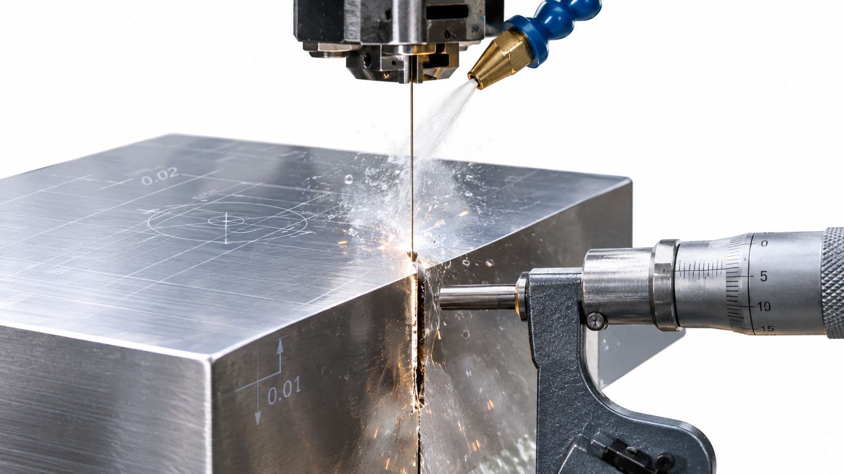
Laser Cutting Precision: A Practical Engineer's Guide
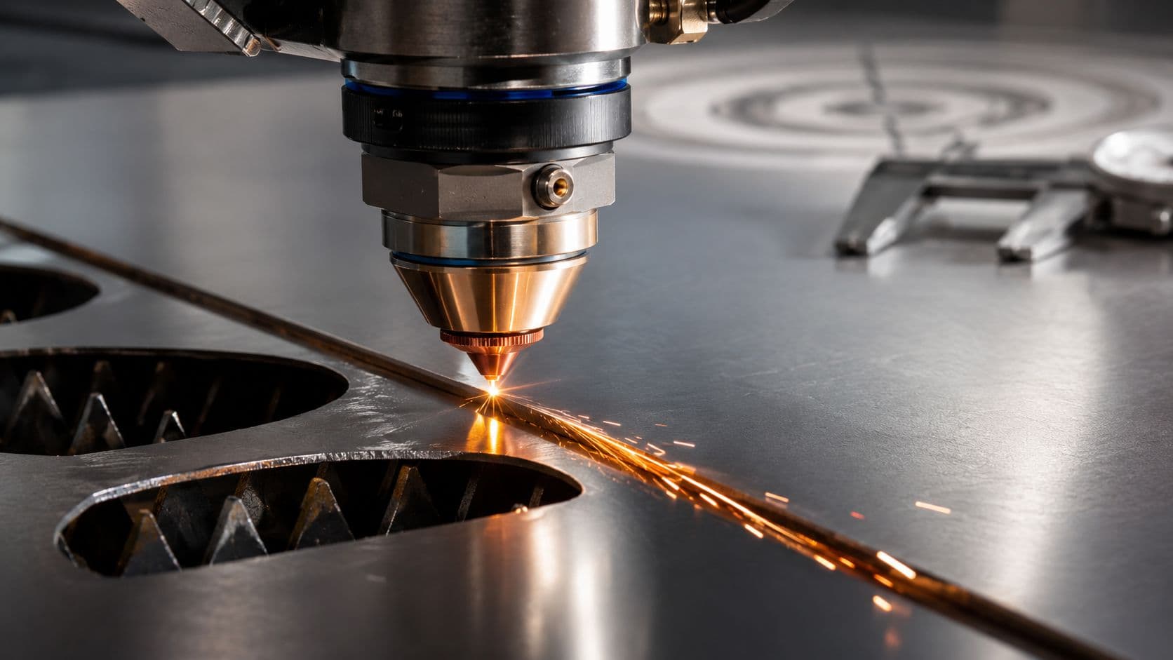
You've probably been in this spot. The CAD is clean, the drawing looks reasonable, and the part still comes back with holes that feel slightly off, edges that need cleanup, or a profile that measures fine in one area and drifts in another. On paper, laser cutting looks simple. In production, laser cutting precision is a moving target controlled by machine condition, material behavior, process settings, and inspection discipline.
That's why tolerance tables alone aren't enough. A supplier can quote a number, but the part only holds that number if the beam is stable, the sheet is consistent, the toolpath is sensible, and someone verifies the result with the right inspection method. The primary work is managing drift before it becomes scrap.
Table of Contents
- What Laser Cutting Precision Really Means
The terms that matter on the shop floor
Why cut quality is part of precision
A Practical Guide to Tolerances by Material and Thickness- What numbers are realistic
Key Drivers of Precision in the Laser Cutting Process- Machine capability and beam type
Design for Manufacturability DFM for High Precision- Design rules that prevent avoidable problems
How Precision is Verified with Quality Control and Inspection- Match the inspection method to the feature
Troubleshooting Common Laser Cutting Precision Issues- When the machine is the problem
When to Choose Laser Cutting vs Alternative Processes
What Laser Cutting Precision Really Means
A design team releases a flat pattern with a tight hole-to-edge callout. The first few parts check out. By the middle of the run, the holes are still close, but not as close, and the assembly starts fighting the locator pins. That is what laser cutting precision looks like in production. It is not a single machine spec. It is the ability to hold the intended geometry from first article through the last sheet, while heat, material variation, nozzle condition, and machine wear keep trying to push the result off target.
On the shop floor, three terms get mixed together and then cause quoting mistakes.
Accuracy is how close the cut lands to the programmed location. Repeatability is how closely the machine can produce that same result again and again. Tolerance is the amount of allowed variation on the drawing. A process can repeat the same offset all day and still miss print. It can also hit the first sheet and drift later as the lens gets dirty, the sheet changes flatness, or assist gas behavior changes.
The terms that matter on the shop floor
A commonly cited industry reference point is ±0.005 inches (±0.127 mm) for standard laser cutting work, with much tighter results possible on advanced fiber laser systems under controlled conditions, as summarized in Laserbend's laser cutting tolerance reference. In practice, those tighter numbers only hold when the feature size, material condition, thickness, nest layout, and maintenance state all support them. Quoting the best-case machine number without those conditions is how tolerance problems get built into the job before cutting starts.
If your drawing mixes profile dimensions, hole locations, and mating features, it helps to compare laser process capability with broader CNC machining tolerance standards and fit expectations. That comparison usually makes one point clear fast. Laser cutting can hold very good tolerances, but it does not behave like a rigid machining process on every feature.

Three process terms deserve constant attention:
- Kerf is the width of material removed by the beam. If kerf shifts because focus, nozzle condition, or material response changes, the part size shifts with it.
- Positioning is where the machine places the cut on the sheet. This controls hole location, slot spacing, tab alignment, and edge distance.
- Dimensional stability is whether the part stays in shape during and after cutting. Residual stress in the sheet, heat input, and part geometry all affect it.
Practical rule: For tight location callouts, ask how the supplier controls drift over a full production run and how feature location is verified, not just what tolerance the machine can hit on a good sample.
Why cut quality is part of precision
A part can measure inside tolerance and still cause assembly trouble. Tapered edges change fit. Dross can hold a part off a datum surface. Local overheating can pull a thin feature out of position by enough to matter, even when the overall profile looks fine.
Generic tolerance charts fall short. They tell you what a machine may achieve, but not why a stable process starts to wander on real jobs. I have seen precision drift come from lot-to-lot sheet hardness changes, poor flatness on larger blanks, worn consumables, and nests that put too much heat into one area before the sheet can relax.
Precision, in production, means the part matches the drawing, assembles without force, and stays consistent across the run. That is the standard that matters.
A Practical Guide to Tolerances by Material and Thickness
A tolerance that works on a 1 mm stainless bracket can fail fast on a 10 mm plate, even on the same laser and the same day. Engineers run into trouble when the drawing carries one blanket number across every feature, material, and thickness, then expects the shop to hold it at production speed.
Use tolerance bands by material, thickness, and feature type.
What numbers are realistic
A commonly cited baseline for laser cutting is about ±0.1 mm (±0.005 inches). As noted in Glorylaser's discussion of laser cutting accuracy, plastics such as acrylic may hold tighter results in stable setups, while polycarbonate often needs more conservative expectations because cut behavior varies more with setup and heat.
For quoting and drawing review, a planning table is more useful than a single headline number. It helps separate what is routine from what is possible with slower cutting, tighter setup control, and more inspection.
| Material | Thickness (mm) | Standard Tolerance (± mm) | High-Precision Tolerance (± mm) |
|---|---|---|---|
| Stainless steel | Thin sheet | Around industry-standard levels | Possible with optimized setup |
| Mild steel | Thin sheet | Around industry-standard levels | Possible on critical features |
| Aluminum | Thin to medium sheet | Around industry-standard levels | Depends heavily on setup and thermal behavior |
| Acrylic | Common sheet gauges | Typically tighter than many general materials | Can be held very tightly in stable setups |
| Polycarbonate | Common sheet gauges | More variable than acrylic | Requires conservative expectations |
If you need a broader tolerance framework for deciding what should stay laser cut and what should be machined afterward, this guide to CNC machining tolerances is a useful reference point.
Why thickness changes the result
Thickness changes the process window. On thin sheet, the beam gets through quickly, heat stays more localized, and feature size is easier to control. As thickness increases, the cut needs more energy and more dwell time. Edge taper, dross risk, and local heat distortion all become harder to manage.
Material variation matters just as much. Two lots of the same nominal material can cut differently if flatness, surface condition, protective film, or hardness shifts. That is one reason a supplier may hold a number on first article parts, then start to drift later in the run unless setup checks and consumable changes are disciplined.
Small features usually tighten the problem. A large outer profile may cut acceptably while a small hole runs oversize, or a narrow slot closes up from heat input and kerf variation. Put the tightest callouts on the features that drive assembly, such as hole location, slot width, edge distance, and fit-critical tabs.
Do not apply one tolerance to the whole profile if only two features matter in the assembly.
In design review, I usually push for three questions. Which dimensions control fit. Which can float with normal sheet process capability. Which features should be cut undersize or oversize on purpose to account for expected process behavior. That approach keeps cost under control and reduces the usual argument between drawing intent and production reality.
If the part needs tighter control across all features, expect trade-offs. The shop may need to slow feed rates, reduce nest density, add more frequent nozzle and focus checks, inspect more parts, or split the work into laser cutting plus a secondary machining step. That is how tight tolerance gets bought in practice.
Key Drivers of Precision in the Laser Cutting Process
A shop can cut first articles that look excellent at 8:00 a.m. and miss size by noon on the same program. The drawing did not change. The machine did not change. Focus drift, nozzle wear, gas instability, sheet variation, and heat buildup did.
Precision comes from process stability over time, not from the laser spec sheet.
Machine capability and beam type
Laser type sets the starting envelope. As outlined in Accurl's laser cutting parameter guide, fiber lasers are generally better suited to metal cutting because the beam is absorbed more efficiently by metals, while CO2 systems still fit many non-metal applications. For metal parts with tight holes, narrow slots, and fit-critical edges, fiber is usually the practical choice because it gives better edge definition at production speeds.
That still does not guarantee a precise part. Two machines with the same source power can produce different results if one has looser motion control, worn optics, poor nozzle centering, or inconsistent height sensing. On older equipment, I expect more variation across a full sheet, especially on small internal features where any motion error or beam instability shows up fast.
Process settings that create drift
Power, feed rate, focus position, assist gas, nozzle condition, and stand-off height have to stay inside a narrow stable window. Shops lose accuracy when they tune for speed alone and treat the rest as secondary.
The usual pattern is predictable. Feed rate goes up, edge lag increases, corners round off, small holes open up, and dross starts forming at the bottom edge. Slow the cut too much and heat input climbs, which can distort thin material or change feature size in dense nests. Precision work is always a balance between throughput and thermal control.
A few variables deserve closer attention because they drift during production, not just during setup:
- Focus position: A small shift in focus can change kerf shape and edge squareness, especially on thicker material.
- Nozzle wear and centering: A damaged or off-center nozzle disturbs gas flow and pushes the cut off its best window.
- Assist gas quality: Pressure variation, contamination, or the wrong gas for the material will show up as rough edges, dross, and inconsistent kerf.
- Height control: If the head follows warped sheet poorly, cut quality changes from one area of the nest to another.
- Heat accumulation: Parts cut late in the sheet can behave differently from parts cut first, particularly in thin stainless and aluminum with dense feature spacing.
Visual cues still matter. A stable cut has consistent spark direction, predictable edge color, and repeatable burr condition. If those cues change during the run, the process is moving, even if the control panel still says the recipe is correct.
Machine wear is another source of slow drift that generic tolerance guides often ignore. Bearings loosen. Belts age. Protective windows pick up contamination. Nozzle seats get nicked. None of those failures need to be dramatic to move a feature out of tolerance. That is why disciplined shops check centering, focus, and consumables on a schedule instead of waiting for obvious scrap.
For design engineers, the practical takeaway is simple. If a part needs tight location and edge quality, ask how the supplier holds the setup stable across the full run, not just on the first few pieces. A shop with strong setup control, preventive maintenance, and clear design for manufacturability review practices will usually beat a shop with a newer machine and weaker process discipline.
Precision drifts for physical reasons. Material changes, consumables wear, heat builds, and alignment moves. Good production control catches that drift before the parts stop fitting.
That is where capable shops separate themselves. They do not just find a recipe that works once. They keep the process centered long enough to ship an entire lot that still matches the drawing.
Design for Manufacturability DFM for High Precision
A part can look clean in CAD and still be expensive, unstable, or impossible to hold on a laser. The problem usually shows up after release. Small slots come back tapered, tabs run hot, hole locations drift after the profile drops free, and the supplier gets blamed for geometry that should have been resolved in the drawing.
Good DFM starts with a simple question. Which features require laser-level precision, and which ones should be opened up, moved, or finished another way?
Design rules that prevent avoidable problems
The first controls are feature size, spacing, and how the drawing handles kerf. As noted in Yihai Laser's tolerance guide, very small features become less stable as thickness increases, and kerf must be accounted for if the finished dimension matters.

If you want a broader product-development view, this practical guide to design for manufacturability review methods is worth checking before drawing release.
Use these checks before sending a part out:
- Compensate for kerf: The programmed path is not the finished edge. Kerf shifts with material, nozzle condition, assist gas, and focus, so a nominal offset that worked on one job may not hold on another.
- Avoid undersized slots and webs: Thin sections heat fast and lose consistency first. If a narrow feature is functionally required, call it out early and confirm the supplier can hold it in that thickness.
- Give internal corners realistic relief: Very sharp internal corners concentrate heat and often leave a rougher, less repeatable result than the model suggests.
- Apply tight tolerances only where the assembly needs them: If one datum pattern drives fit, hold that pattern tightly and let noncritical profiles float more.
- Separate laser-cut features from post-machined features: If a hole location drives bearing fit, pin alignment, or stack-up, it may belong in a secondary machining step, not in the laser operation.
A practical rule in production is to design around process drift, not just nominal capability. Material flatness changes. Thickness varies within the sheet. Cut quality near a heat-affected area can differ from cut quality in a cool zone. Drawings that leave no room for that variation often create inspection fights and rework.
Layout and sequencing decisions
Sheet layout affects precision more than many design teams expect. Tight nesting improves yield, but it also packs heat into a smaller area and changes how parts move as internal stress is released. On thin stainless and aluminum, that can be enough to shift a small feature from acceptable to marginal.
Cut sequence matters just as much. Experienced programmers usually cut internal features while the part is still fully supported, then release the outer profile later. That reduces movement and gives small holes, tabs, and slots a better chance of staying on size and on location.
One detail I watch closely is the distance between critical features and the outside profile. A hole pattern placed too close to the edge of a light-gauge part is harder to keep stable once that perimeter starts to free up. If the assembly allows it, move the pattern inward or leave more supporting material until later in the route.
Shop-floor advice: If a design packs small holes, narrow bridges, and a tight outer contour into one area, ask for a programming review before release. That conversation is cheaper than sorting a lot of borderline parts.
Good DFM for laser cutting is disciplined design. Make feature sizes realistic, leave room for thermal behavior, and reserve tight tolerances for the dimensions that determine fit. That usually lowers cost, shortens programming time, and holds precision more consistently across the full run instead of only on the first sheet.
How Precision is Verified with Quality Control and Inspection
A tolerance is only real if the measurement method can resolve it cleanly. That sounds obvious, but a lot of inspection plans still rely on tools that are fine for general dimensions and weak for small features, edge condition, or positional relationships.
Match the inspection method to the feature

For straightforward outside dimensions, digital calipers often do the job. They're fast, accessible, and suitable for routine checks when the tolerance isn't extremely tight. The problem starts when teams use calipers to validate geometry they can't properly access or align well.
For higher-confidence verification, different tools fit different tasks:
- Micrometers: Better than calipers for thickness or simple edge-to-edge checks where contact and alignment are controlled.
- Optical comparators: Useful for profiles, radii, and cut-shape evaluation when edge form matters as much as size.
- CMMs: Best for feature location, datum-based inspection, and complex geometry where relationships between features matter.
- Non-contact scanning systems: Helpful when you need broad shape capture or quick comparison to CAD on more complex parts.
If you're defining an inspection plan for prototypes or first articles, this guide to dimensional inspection gives a practical framework.
What a useful inspection plan looks like
The most useful inspection reports don't drown the reader in dimensions. They focus on the dimensions that drive assembly, sealing, motion, or downstream processing.
A sensible plan usually includes:
- Datum-based checks for hole patterns, slots, and profile locations.
- Edge-condition review for dross, taper, and visible thermal damage.
- Targeted sampling across the sheet or run, not just a single favorable part.
- Clear reaction criteria if drift starts showing up between early and later parts.
If the drawing's critical feature is location, inspect location directly. Don't infer it from a chain of edge measurements and hope the stack-up tells the truth.
Inspection should confirm process stability, not just catch isolated bad parts. That's the difference between quality control and sorting.
Troubleshooting Common Laser Cutting Precision Issues
A shop can hold tolerance on the first sheets in the morning, then start missing hole size or profile location by mid-shift without changing the program once. That kind of drift usually comes from wear, material variation, or heat buildup, not a bad drawing and not always an optical problem.

Troubleshooting gets faster when the team stops asking, "What setting should we change?" and starts asking, "What drift pattern are we seeing?" Precision failures leave fingerprints. Circularity errors point to one set of causes. Edge roughness that changes across the sheet points to another. If the first part is good and the twentieth is not, look at thermal load and machine condition before rewriting the cut recipe.
When the machine is the problem
Motion wear shows up long before a machine is obviously broken. Backlash, loose drive components, worn bearings, poor axis squareness, and calibration drift all push cut geometry away from nominal. Small holes usually expose it first because they force more direction changes and higher dynamic response than long straight profiles.
As noted in Accurl's review of common fiber laser cutting problems, roundness error can come from mechanical backlash in the motion system rather than the beam path. That matches what shows up on the floor. Operators often clean the lens, adjust focus, and slow feed rate, but the bad circle came from axis behavior, not optics.
Watch for these patterns:
- Circles, arcs, and tight radii go out first: The machine has to reverse direction cleanly. Wear and backlash show up there before they show up on straight edges.
- Error grows over weeks instead of appearing all at once: That usually points to mechanical wear, loose components, or calibration drift.
- Parts cut in one orientation measure differently from mirrored parts: Check axis alignment, servo tuning, and machine geometry.
- Small internal features fail while outside profiles still pass: Dynamic accuracy is degrading before static positioning looks obviously bad.
The fix depends on the symptom. If round holes become slightly oval, check backlash and servo response. If the whole nest shifts, check datum pickup, coordinate calibration, and sheet registration. If edge quality drops with no dimensional pattern, then inspect nozzle condition, centering, assist gas flow, and optics.
When the material is the problem
Material variation causes more precision trouble than many design teams expect. Sheet thickness changes, residual stress, flatness error, surface scale, protective film behavior, and alloy-to-alloy reflectivity differences all move the process window. A program that runs cleanly on one batch can produce taper, burr, or inconsistent kerf on the next batch even though the machine settings are unchanged.
A few common signs show up fast:
- Cut quality changes by sheet location: One corner cuts clean, another leaves more dross or taper.
- Piercing becomes inconsistent on the same nest: Material thickness, coating, or flatness is changing the energy input at the work surface.
- Thin webs distort near the end of the run: Local heat buildup and stress relief are moving the part as cutting progresses.
- Feature size drifts after a material lot change: The process was tuned to the previous sheet condition, not the current one.
The settings did not change. The sheet changed.
DFM decisions matter in practice. If a part has narrow bridges, dense hole patterns, or tight features packed into a hot zone, even modest material stress can move the cut enough to miss tolerance. Opening spacing between features, changing cut sequence, adding microtabs where appropriate, or relaxing a non-critical cosmetic edge can stabilize a job without touching the nominal design intent.
Read the defect before changing the recipe
Good troubleshooting starts at the part, not at the control screen. Look at where the error appears, whether it is repeatable, and whether it follows geometry, sheet location, or time in the run.
Use this sequence:
- Separate geometry error from edge-quality error. A size or shape problem usually points toward motion, compensation, or thermal movement. A rough edge or heavy dross usually points toward the process window, nozzle condition, gas flow, or focus.
- Check whether the defect follows the feature type. If only holes and slots fail, investigate dynamic machine behavior and lead-in strategy. If every edge is affected, look broader.
- Check whether the defect follows sheet position. Localized problems often come from flatness variation, thickness change, or heat concentration in the nest.
- Check whether the defect gets worse later in the run. That suggests thermal distortion, consumable wear, or machine components drifting as they warm up.
- Confirm before editing the program. Measure several parts from different areas of the sheet and different points in the run. One bad sample can send the team toward the wrong fix.
A few practical examples help. If holes are undersized and heavily tapered, first check focus, nozzle centering, and assist gas before changing CAD compensation. If outside dimensions are drifting but edge finish still looks good, inspect motion calibration and backlash. If parts near the center of a dense nest are worse than parts at the perimeter, reduce local heat load with sequence changes or more spacing.
The expensive mistake is applying the same correction to every defect. Slower cutting can improve one feature and increase heat distortion in another. More power can clean up a thick section and wash out a thin detail. Tight precision work depends on matching the fix to the failure mode, then confirming the result with repeat measurements across the sheet and across time.
When to Choose Laser Cutting vs Alternative Processes
Laser cutting is the right choice when you need fast, accurate 2D profiles in sheet material with clean edges and efficient production flow. It usually wins when the geometry is planar, the part count is meaningful, and you want a strong balance of precision, speed, and cost.
Choose CNC milling when the feature is three-dimensional, when you need machined datums, or when the tolerance stack depends on controlled surfaces rather than a cut profile. Choose waterjet when heat input is the main concern and edge metallurgy or thermal effects can't be tolerated. Choose plasma when cost and throughput matter more than fine detail or edge quality.
Laser cutting sits in the middle of the manufacturing toolkit in a very useful way. It's often more precise and cleaner than rougher thermal processes, and much faster and more economical than machining for sheet profiles. The key is using it where it's strongest, then designing and inspecting the part like a manufacturing engineer, not like the process is magically perfect.
If you need laser-cut prototypes or production parts with tighter process control, FIRMFG can support quoting, DFM review, fabrication, and dimensional inspection across sheet metal and adjacent manufacturing processes. Upload the CAD, flag the critical features, and get feedback before tolerance problems turn into rework.