Master Sheet Metal Bending: Engineer's Guide
You send out a prototype bracket on Friday. By Monday, assembly says the holes no longer line up, the flange angle is off, and one corner has started to tear near a slot. The CAD model looked clean. The flat pattern nested well. The laser cut parts were fine. The failure happened in the bend.
That gap between a correct 3D model and a manufacturable bent part is where most sheet metal projects get expensive. In prototyping and low-volume work, that cost shows up fast. You don't have the cushion of dedicated hard tooling, process tuning over huge runs, or extra inventory to hide mistakes. One wrong bend assumption can force a redraw, a new flat, another setup, and another first article.
Good sheet metal bending work starts long before the press brake cycles. It starts when the design engineer understands what the punch, die, material, and operator will do to the part.
Table of Contents
- Why Bent Sheet Metal Parts Fail and How to Prevent It
The common failure chain
Prevention starts with design intent
Core Bending Methods Explained- What the punch and die are really doing
Material Behavior and Critical Bend Calculations- Why metal moves the way it does
- Using K-factor without treating it like a constant
- Bend allowance, bend deduction, and what actually matters
- Springback is where theory meets the machine
Selecting the Right Press Brake Tooling and Dies- Tool geometry drives part geometry
DFM Best Practices for Sheet Metal Bending- Standardize the variables that drive bend quality
- Design edge features like they will affect the bend, because they will
- What matters most in prototypes and low-volume runs
Identifying and Fixing Common Bending Defects- Symptom, cause, and fix
Partnering for Success in Fabrication
Why Bent Sheet Metal Parts Fail and How to Prevent It
Bent sheet metal parts usually fail for boring reasons, not exotic ones. The bend radius was too sharp for the alloy. The hole sat too close to the bend line. The flat pattern assumed one K-factor, while the shop formed the part with a different method. A U-channel was modeled as if any punch could reach it, then collided with the tooling during forming.
In prototype work, these mistakes stack on each other. A part might still bend, but it won't bend predictably. That matters more than whether a press brake can physically force the shape. If the process isn't predictable, dimensions drift, springback changes the angle, and secondary operations start compensating for a geometry problem that should have been solved in design.
The common failure chain
A typical chain looks like this:
- CAD assumes ideal geometry: The model treats bends as perfect transitions instead of formed zones with stretching, compression, and springback.
- The flat pattern inherits the wrong assumptions: Bend allowance or deduction doesn't match the actual process.
- Tooling imposes a different reality: The operator selects a practical punch and die set that works on the machine, not the abstract one implied by CAD.
- Inspection catches the miss late: Assembly discovers hole shift, flange mismatch, or cosmetic damage after parts are already bent and finished.
Practical rule: If a bent part must locate another component, treat the bend as a controlled manufacturing feature, not just a geometric edge in CAD.
The fix isn't complicated, but it does require discipline. Pick a realistic bending method. Set bend radii that match the material and available tooling. Keep features out of the high-strain zone unless you have a very good reason. Then validate the first article based on the formed part, not just the flat.
Prevention starts with design intent
What works is simple, repeatable geometry. Consistent bend radii. Adequate clearance for tooling. Features placed with the forming sequence in mind. Tolerances applied where function needs them, not sprayed across every flange.
What doesn't work is designing a part as if every shop has custom punches ready, every alloy bends the same way, and every bend lands exactly where the CAD system predicts by default.
When design and fabrication are aligned, sheet metal bending is fast, flexible, and economical for prototypes and small runs. When they aren't, the press brake becomes the place where hidden design assumptions show up as scrap.
Core Bending Methods Explained
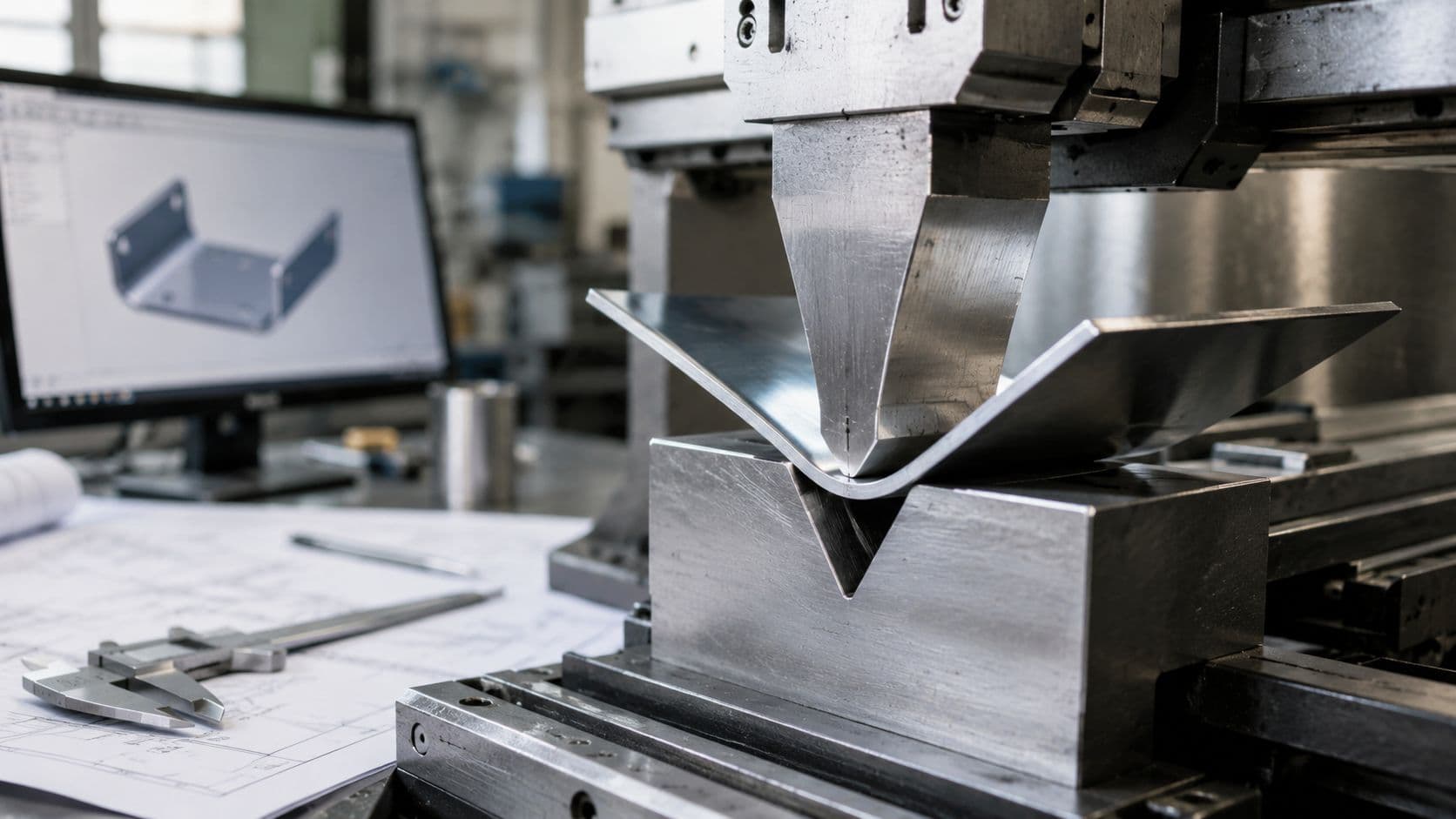
Most press brake work comes down to three methods: air bending, bottom bending, and coining. They all use a punch and die, but they don't form metal the same way, and they don't give you the same trade-offs in accuracy, tonnage, tooling flexibility, or material stress.
A useful way to think about them is this. If you're shaping clay, you can press it lightly into a form, press it firmly into the form, or stamp it hard enough to leave a permanent imprint. Metals aren't clay, but the analogy helps clarify what changes from one method to the next.

What the punch and die are really doing
Air bending is the most flexible option. The punch pushes the sheet into a V-die, but the material doesn't fully bottom out against the die surfaces. The final angle depends on punch penetration and the material's springback. That makes air bending versatile and efficient for prototyping, because one die can support a range of angles.
The trade-off is control. Since the material rebounds after unloading, angle consistency depends more heavily on material variation, setup, and compensation.
Bottom bending drives the sheet more fully into the die. The part contacts the die walls more completely, which reduces springback and improves angle repeatability. Shops use it when they need tighter angular control than air bending usually delivers, but without going all the way to coining.
The penalty is lower flexibility. Bottom bending typically ties the bend more closely to a specific die geometry, so setup options narrow.
Coining applies enough force to plastically deform the bend zone more aggressively. The punch effectively imprints the bend shape into the material, which minimizes springback and produces very accurate angles. It's the most force-intensive of the three and it puts the most demand on tooling and machine capacity.
For design engineers, the practical difference is this table:
| Method | Best use | Main advantage | Main limitation |
|---|---|---|---|
| Air bending | Prototypes, mixed-angle parts, flexible setups | Versatility | More springback sensitivity |
| Bottom bending | Parts needing tighter angle control | Better repeatability | Less tooling flexibility |
| Coining | Precision bends with minimal rebound | Highest angular accuracy | Highest force and tooling stress |
Shops usually prefer air bending for early iterations because it gives them room to tune the angle without changing the whole setup.
Where roll bending fits
Roll bending is a different process entirely. Instead of creating a discrete angle with a press brake, it passes sheet or plate through rollers to create large-radius curves, arcs, or cylinders.
That distinction matters in design reviews. If you model a broad smooth curve and send it to a shop expecting standard press brake hits, the result may show segmented facets instead of a continuous radius. If the geometry really needs a cylindrical or sweeping curve, roll bending is often the right process.
Use press brake methods for flanges, channels, brackets, enclosures, and crisp angular forms. Use roll bending when the shape is curved.
Material Behavior and Critical Bend Calculations
A prototype bracket looks fine in CAD, the flat pattern exports cleanly, and the first parts still miss the target angle or crack at the bend line. That gap usually comes from one mistake. The model assumes metal bends in a neat geometric arc. The press brake forms real material with memory, grain direction, temper, and process variation.

The material does three things during bending. The inside face compresses. The outside face stretches. Between them sits the neutral axis, the layer that changes length the least. Flat pattern accuracy depends on where that neutral axis ends up, not where a default CAD setting assumes it should be.
Why metal moves the way it does
Material choice sets the limits before the operator touches the pedal. Softer, more ductile alloys usually tolerate tighter bends. Harder tempers and higher-strength materials need more radius and more margin. In low-volume work, that matters because you often do not have time to tune around a poor material decision after the parts are cut.
6061-T6 aluminum is a common example. It machines well and looks attractive in a design review, but it is less forgiving in tight bends than alloys such as 5052. If a prototype needs sharp flanges in aluminum, the alloy and temper should be reviewed early against the shop's actual forming limits, not after the first cracked sample.
If you are still comparing options, a guide to common manufacturing materials and tempers helps frame the discussion. Strength values alone do not predict bend success. Temper, grain direction, surface condition, and available stock form all affect what the shop can produce repeatably.
Using K-factor without treating it like a constant
K-factor describes the neutral axis location as a fraction of material thickness. That sounds abstract until a flat pattern comes out wrong by a few tenths and every tab in an enclosure stops lining up.
In practice, K-factor works like the hinge line in a scored fold. A broad, gentle fold places that hinge differently than a tight crease. Sheet metal behaves the same way. Change the bend method, inside radius, or material condition, and the neutral axis shifts.
That is why one fixed K-factor across every part library causes trouble. Air bending, bottom bending, thin stainless, and thick aluminum should not all inherit the same value by default. For prototype and low-volume jobs, I would rather see a validated shop value tied to a known punch and die setup than a theoretically correct number pulled from a generic table.
Bend allowance, bend deduction, and what actually matters
Design teams tend to argue about bend allowance versus bend deduction as if one method is more correct. Both are valid. They are just two ways to describe the same geometry.
- Bend allowance is the developed length of the neutral axis through the bend.
- Bend deduction is the amount subtracted from the sum of outside flange dimensions to get the flat length.
Use whichever method matches your CAD system, drawing convention, and quoting workflow. The main failure point is not the formula. It is using inputs that do not match production. If the CAD model assumes a 1.0t inside radius and the shop forms the part over a wider V-die that produces a larger radius, the flat pattern will drift even if the arithmetic is perfect.
For one-off prototypes, that drift may only mean a quick correction. For a short production run, it means recut blanks, wasted setup time, and a schedule hit that the original model never showed.
Springback is where theory meets the machine
Springback is elastic recovery after forming. The punch releases, the material relaxes, and the angle opens up. Every shop expects this. The amount changes with alloy, temper, thickness, bend radius, and forming method.
Here, design choices show up on the floor.
A tight bend in mild steel may be routine. The same nominal geometry in stainless or 6061-T6 can need more overbend, a larger inside radius, or a different process plan to hit the final angle without surface damage or cracking. That is why bend tables built from actual shop trials outperform generic defaults, especially in prototype work where you are still proving the design.
A few habits prevent most of the rework:
- Match bend values to the actual process. Separate assumptions for air bending and bottom bending.
- Keep radii consistent where the function allows it. Fewer radius changes usually mean simpler setup and faster first-article correction.
- Review crack-sensitive materials before release. Tight bends in less ductile tempers should be challenged in design, not discovered at the brake.
- Validate with a first article from production-intent material. Scrap from a trial bend costs less than revising an assembled batch.
Good bend calculations are not just math. They are a record of how a specific material behaves in a specific process. Once the CAD model reflects that reality, flat patterns become far more predictable, and prototype parts stop teaching avoidable lessons.
Selecting the Right Press Brake Tooling and Dies
Tooling decides whether a design is straightforward, awkward, or impossible. The punch forms the top side of the bend. The die supports and shapes the bottom side. If those two tools don't match the part geometry, material, and bend sequence, the shop can still sometimes force the bend, but it won't do it cleanly or repeatably.

Tool geometry drives part geometry
Designers often focus on the finished profile and forget the path the tool must take to get there. A straight punch works well for many simple flanges. It doesn't work well when return flanges or deep channels put formed walls in the way. That's where a gooseneck punch earns its place. Its relieved shape lets the tool reach into U-channels and offset forms without the already-bent part crashing into the punch body.
The lower tool matters just as much. Most general sheet metal bending uses some form of V-die. The width of that V opening strongly influences forming behavior, including the inside radius produced during air bending. Ignore that relationship and you get the usual problems: angle inconsistency, visible marking, distortion, or cracking in less forgiving materials.
Common tooling choices and their limits
A practical shop-floor view looks like this:
- Straight punches: Good for simple bends with clear tool access. They are efficient and common, but they run into clearance problems quickly on boxed or channeled parts.
- Gooseneck punches: Necessary when formed flanges would otherwise interfere with the tool. They solve geometry access issues, not material issues.
- Standard V-dies: The workhorse for air bending and many bottom-bending setups. They support a wide range of parts, but only if the opening is sensible for the thickness and target radius.
- Specialty tooling: Useful for hems, offsets, and unusual profiles, but it raises setup complexity. In low-volume work, custom tooling can erase the cost advantage of simple press brake fabrication.
A common rule of thumb in shops is the 8x rule for V-die selection, meaning designers often start by thinking in terms of a die opening around several times the material thickness. The exact choice still depends on material, radius target, method, and machine capability, so treat that rule as a starting point rather than a promise.
If the part only works with one exotic tool path, it isn't robust enough for prototype fabrication yet.
For low-volume projects, the best designs give the fabricator options. They don't demand a custom punch profile to make a routine flange, and they don't put adjacent bends so close that only a very specific tool set can reach them in sequence.
DFM Best Practices for Sheet Metal Bending
A prototype often looks clean in CAD, then comes off the brake with pulled holes, a twisted flange, or an angle that misses the assembly by a degree or two. The drawing was not wrong. The part was designed without enough margin for how sheet metal forms. Good DFM closes that gap between the model and the machine.

Standardize the variables that drive bend quality
Low-volume fabrication gets expensive when every bend asks the operator to solve a different problem. Mixed bend radii, marginal flange lengths, changing material conditions, and cosmetic features near bend lines all increase setup time and first-article risk. In production, that may be absorbed across a large run. In prototyping, it shows up immediately as delay and rework.
Start by making the part predictable to form:
| Design choice | What works | What usually causes trouble |
|---|---|---|
| Bend radius | Keep it consistent across the part | Mixing sharp and generous radii without a functional reason |
| Flange design | Leave enough material for stable forming and gauging | Very short flanges that are hard to control |
| Feature placement | Keep cutouts away from the strain zone | Holes and slots crowding the bend line |
| Bend orientation | Consider grain and part function together | Tight bends in unfavorable material orientation |
Feature spacing is one of the first things to check. SendCutSend recommends placing holes and slots at least 4 times material thickness away from bend lines and inside corners to reduce distortion risk, based on its sheet metal bending design guidelines. If function forces a feature closer than that, treat it as an exception that needs relief geometry, tolerance review, or a different process choice.
Design edge features like they will affect the bend, because they will
A bend line does not act only at the line. The surrounding material has to stretch, compress, and slide into a new shape. Cutouts interrupt that flow. A narrow slot near a flange edge can make one side of the bend act softer than the other. A decorative perforation can turn a stable flange into one that waves or pulls out of angle.
That is why bend reliefs, notch shapes, and edge distances matter. They are strain-control features, not drafting details.
Komaspec's guide to sheet metal bending notes that edge distortion near bends is a common source of prototype failure when relief design is inadequate. That matches what shops see every day. Symmetric, well-spaced features usually form predictably. Irregular cutouts near bend ends usually need more review than the CAD model suggests.
For early revisions, it helps to evaluate these areas through a broader design for manufacturability process. The bend is only one operation. Blank cutting method, grain direction, tolerance stack, bend sequence, and assembly datums all affect whether the first parts are usable.
Relief geometry is a strain-management feature.
What matters most in prototypes and low-volume runs
Prototype parts should leave room for learning. A design that depends on the shortest possible flange, the tightest feature spacing, and no visible marking can be made, but it usually costs more time to prove out than the first revision justifies.
The better approach is to protect function first and compress process variation second.
- Use repeatable bend conditions: Similar bends across the part reduce setup changes and make angle correction easier.
- Give nearby features margin: If a hole, slot, or notch sits near a bend, expect local distortion unless the geometry was planned for it.
- Apply tight tolerances selectively: Hold fit, sealing, alignment, and load-path dimensions tightly. Let noncritical formed dimensions breathe where the process needs room.
- Check bend sequence in the design stage: A part that can only be formed in one narrow sequence is harder to prototype and harder to revise.
- Avoid unnecessary uniqueness: If a feature adds no functional value but forces extra setup decisions, remove it from the first build.
The practical test is simple. If the part can tolerate normal material variation, standard bend sequencing, and a reasonable amount of springback compensation, it is manufacturable. If it only works under one very narrow set of shop conditions, the design still needs work.
Identifying and Fixing Common Bending Defects
You can learn a lot from a bad bend if you read it correctly. Most defects point back to a mismatch between material behavior, tool choice, and design geometry. The useful framework is simple: symptom, cause, fix.
Symptom, cause, and fix
Cracking at the outside of the bend usually means the material was stretched beyond what it could tolerate. Common causes are a radius that's too tight, an unfavorable grain orientation, or a brittle temper. The fix is usually to increase the inside radius, revisit material choice, or reorient the part if grain direction is driving the crack.
Wrinkling on the inside face points to compression instability. Thin material, weak support, or an unsuitable process setup can let the inside face buckle rather than form smoothly. A larger radius or different setup can help, and sometimes the part needs better geometric support in the design.
Galling or heavy tool marks show that the interface between sheet and tooling isn't clean enough for the cosmetic or functional requirement. Tool condition, surface finish expectations, and material sensitivity all play a role. If appearance matters, call it out early so the shop can plan around marking risk.
Angular deviation is the defect most engineers see first. The flange doesn't land where the print expects. That's usually springback compensation, material variation, or tooling selection showing up in the final angle. The fix is process adjustment, not wishful inspection.
What to check on a first article
Start with function, then work outward.
- Measure bend angle first: A protractor, angle gauge, or CMM will tell you quickly whether springback compensation is under control.
- Check flange lengths from the formed condition: Don't assume a correct flat produced a correct bent dimension.
- Inspect holes and slots near bends: Look for ovaling, edge pull, tearing, or local distortion.
- Look at the surface in good light: Cosmetic damage often shows up before dimensional drift becomes obvious.
A first article should answer one question before any other. Is the process stable enough to make the next part the same way?
That question leads to better conversations with your fabricator. Instead of saying the angle is wrong, you can ask whether the issue came from springback, tool access, feature proximity, or material behavior. That's a much faster route to a corrected revision.
Partnering for Success in Fabrication
A prototype often looks clean in CAD and still turns into a shop-floor argument by the first bend. The flange that fit on screen now collides with the punch body. The inside radius calls for tooling the shop does not keep loaded. The angle can be made, but only with extra hits, slower setup, and more inspection.
That gap between design intent and fabrication reality is where cost and lead time start to climb, especially in prototyping and low-volume work. One extra bend angle, one hole placed too close to a form, or one tolerance copied from a machined part can force workarounds that add labor without improving function.
A good fabrication partner catches those issues before metal is cut. The review should focus on what will drive outcomes in the brake press: bend sequence, tool access, allowable radius, grain direction, feature distance from bends, and which dimensions need tight control after forming. That early conversation matters more on five parts than on five thousand, because setup time dominates small runs.
Use the shop early, not just the quote form. A supplier that offers sheet metal fabrication support should be able to tell you which rule is protecting function, which one is protecting yield, and which one is a house preference you can relax.
FIRMFG provides sheet metal, machining, additive, and inspection workflows for teams moving from concept to formed parts. The practical value is simple: fewer revision loops, fewer preventable tooling conflicts, and first articles that answer the key question, whether the process can repeat reliably before the next prototype run.