What Is Design for Manufacturability: Understanding Design
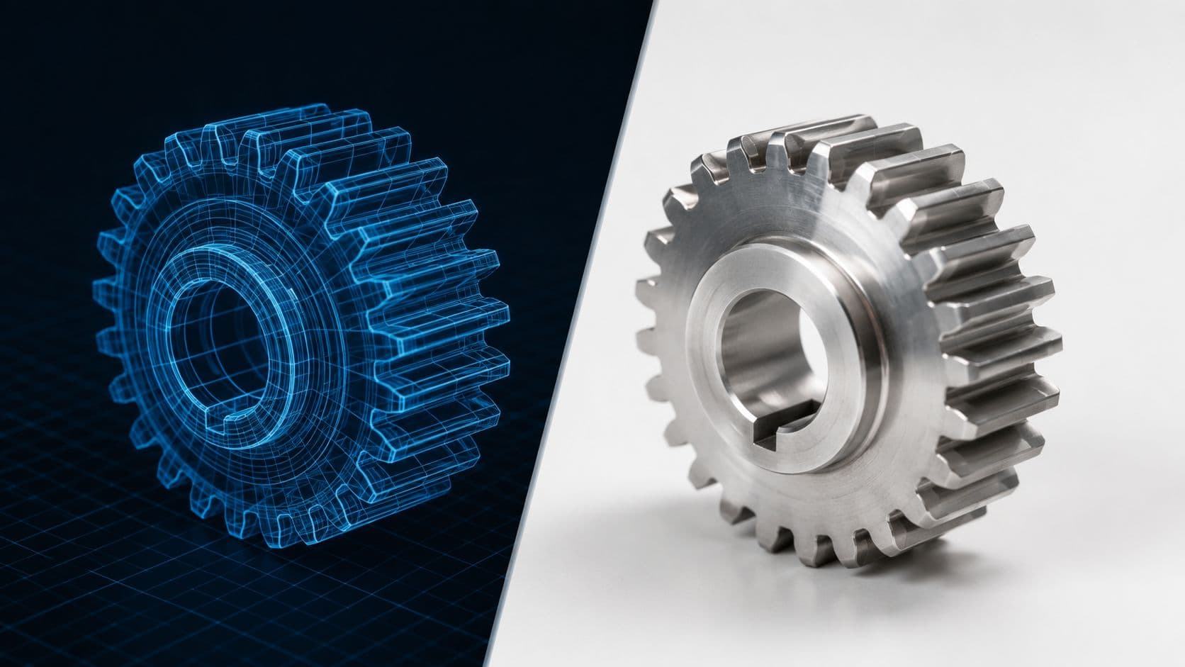
You're probably in one of two situations right now. Either you've got a CAD model that looks clean on screen but keeps coming back from suppliers with painful feedback, or you're trying to move from prototype to a short production run and realizing the rules for making 20 parts are not the same as the rules for making 200,000.
That's where design for manufacturability, or DFM, matters. In plain terms, what is design for manufacturability? It's the discipline of shaping a product so it can be made, repeatedly, at the cost, speed, and quality your project requires. Not in theory. In practice, on physical machines, with available materials, operators, tooling, and inspection constraints.
For hardware startups and NPI teams, this gets even more important in the 10 to 5,000 unit range. At that volume, you're often balancing CNC machining against rapid tooling, deciding whether a 3D printed part is a valid bridge or a dead end, and trying to avoid locking yourself into production assumptions too early. Good DFM doesn't make a design boring. It makes it buildable.
Table of Contents
- Why Your Perfect Design Might Be Unmanufacturable
Where teams usually get blindsided
What DFM actually fixes
The Core Principles of Design for Manufacturability- Simplify what the machine has to do
- Standardize what you can buy
- Match materials to the process
- Design the assembly path early
- Treat low-volume as its own problem
The Tangible Business Benefits of Adopting DFM- Cost shows up in more places than part price
Process-Specific DFM Rules and Guidelines- CNC machining
- Injection molding
- 3D printing SLA and SLS
- Sheet metal fabrication
- Vacuum casting
- DFM quick reference by manufacturing process
Common DFM Pitfalls and How to Avoid Them- Designing in a silo
- Over-tolerancing every feature
- Choosing the wrong process for the stage
- Designing a prototype that cannot mature into production
- Ignoring assembly and inspection until the end
- Treating DFM as a late-stage cleanup task
Collaborating with Your Manufacturing Partner for DFM- Send a quote-ready package
Your Next Steps to Implementing DFM Today- A practical design review checklist
Why Your Perfect Design Might Be Unmanufacturable
A familiar scenario. The industrial design is approved. The CAD is detailed. The assembly looks sharp in SolidWorks or Fusion. Then the quote comes back with questions that weren't in the design review.
Can this internal corner be machined? Why is this wall so thin next to a tapped hole? Does this molded part have draft? Why are the tolerances on cosmetic surfaces tighter than the functional datums? Why does the STL not match the 2D drawing?
The part didn't fail because the concept was weak. It failed because the design team solved the product problem without fully solving the manufacturing problem.
Where teams usually get blindsided
The first surprise is often geometry. A part can be perfectly valid in CAD and still be awkward, expensive, or impossible to make with standard tooling. Deep ribs, trapped undercuts, narrow internal pockets, and sharp inside corners all look harmless on screen. On the shop floor, each one translates into tool access issues, fixturing complexity, extra setups, support structures, secondary operations, or all of the above.
The second surprise is documentation. A design package can contain enough information to model a part but not enough to manufacture it consistently. Siemens notes that 70% of manufacturing jobs could be delayed or held on hold due to incorrect documentation, unmanufacturable design data, or unfinished designs, which is exactly why DFM has to happen early, not after release to production (Siemens on shifting DFM left in the design process).
Practical rule: If your first meaningful manufacturability review happens after RFQ, you're already late.
What DFM actually fixes
DFM is the habit of asking better questions while the design is still easy to change.
- Can this feature be made with standard tools?
- Does this tolerance matter to function, or did we add it by default?
- Are we selecting the right process for the actual build quantity?
- Will this design still work when a machinist, mold maker, or technician has to build it repeatedly?
In practice, DFM prevents the classic late-stage loop: supplier feedback, redesign, new quote, updated prototype, and another slipped schedule. It replaces “Why is this so expensive?” with “What geometry, tolerance, or process choice is driving the quote?”
That's the answer to what is design for manufacturability. It's not a checklist someone runs at the end. It's a way of designing so your first part is much closer to your production part.
The Core Principles of Design for Manufacturability
A lot of DFM advice gets reduced to slogans. Keep it simple. Use standard parts. Add draft. Those are fine as reminders, but they're not enough when you're trying to get a product through prototyping and into a low-volume build without wasting time.

Simplify what the machine has to do
A good first pass is to inspect every feature and ask whether it adds function or only adds manufacturing effort.
A pocket with radiused corners is easier to machine than one that forces tiny tools. A housing split line that follows a natural molding direction is easier to tool than one that creates side actions. A printed bracket with self-supporting faces is easier to finish than one built around support-heavy overhangs.
Complexity isn't always bad. Unnecessary complexity is.
Standardize what you can buy
Standardization is one of the least glamorous and highest-value DFM moves. If your assembly uses three screw head types, two thread standards, and a custom standoff that could have been an off-the-shelf part, you've added purchasing friction, assembly risk, and avoidable cost.
Think of standard components like a known-good toolbox. Common fasteners, bearings, inserts, seals, and stock material sizes reduce surprises because suppliers already know how to source and process them.
A useful companion read is this practical engineering guide to design for manufacturability, especially if you're building internal review standards.
Match materials to the process
Teams often choose material by performance alone, then discover the selected process hates that choice. A plastic that looks right on paper may machine poorly, print with fragile thin edges, or demand tooling choices that don't make sense for a short run.
Material selection works best when you weigh four things together:
- Functional need: strength, stiffness, wear, chemical resistance, temperature.
- Process fit: machinability, moldability, print behavior, post-processing.
- Supply practicality: availability, stock forms, lead time stability.
- Volume logic: whether the material choice still makes sense at your planned run size.
Design the assembly path early
A part can be individually manufacturable and still create an assembly mess. This shows up when components only fit in one awkward sequence, fasteners are inaccessible, cables fight the enclosure, or orientation mistakes are easy to make.
Good DFM overlaps with design for assembly here. Add self-locating features. Give tools room to reach screws. Avoid mirrored parts that look similar but install differently. If an operator has to improvise during assembly, the design is still immature.
The cleanest CAD model often loses to the part that can be fixtured, assembled, and inspected without special handling.
Treat low-volume as its own problem
Many guides often fall short. They jump from prototyping straight to mass production rules and skip the short-run reality most hardware teams live in.
The DFMA discussion of the 10 to 5,000 unit short-run sweet spot makes an important point: most DFM content treats low-volume and high-volume as opposites, while short-run production has its own trade-offs. It also notes that relaxing tolerances from molding precision to shop standard outside functional interfaces can reduce small-batch costs by 20 to 40% without sacrificing function.
That matters because the right answer for 200 units is often different from the right answer for 200,000. In low-volume work, you usually win by reducing setup pain, avoiding expensive tooling features, and accepting process-appropriate cosmetics and tolerances where function allows.
The Tangible Business Benefits of Adopting DFM
DFM isn't an academic exercise. It changes budget conversations, schedule risk, supplier options, and warranty behavior. The teams that use it well spend less time firefighting because fewer bad assumptions survive into the build.
Cost shows up in more places than part price
The quoted piece price is often the first consideration. That matters, but it's only one part of the cost picture.
A design with fewer custom features usually needs less setup time. A part that uses standard cutters and common stock sizes tends to quote more cleanly. An assembly with fewer unique fasteners is easier to buy, kit, build, and inspect. Even before production starts, DFM reduces the hidden labor that burns hours in engineering, sourcing, and quality.
That's why experienced teams don't ask only, “What does this part cost?” They ask, “What design choice is forcing this cost?”
Speed comes from avoiding rework loops
Short-run programs usually don't die because one part is hard. They stall because every problem appears late.
When a supplier flags an inaccessible feature, a sink-prone wall transition, or a geometry change that requires a new fixture strategy, your schedule slips in small but compounding increments. Procurement waits. Test plans shift. Assemblies miss review dates.
DFM shortens that loop by moving decisions upstream. You spend more time in design reviews and less time revising released files. For startups preparing for NPI, that can be the difference between a controlled pilot build and a sequence of rushed engineering changes.
Quality and sustainability start in the model
A manufacturable design is usually a more repeatable design. It produces fewer borderline parts, fewer judgment calls on the floor, and fewer inspection arguments about what the drawing really meant.
There's also a sustainability angle that gets overlooked. Apriori notes that 80% of a product's total environmental impact is determined in the early design phase, which is why DFM belongs in the same conversation as waste reduction, tooling efficiency, and material usage (Apriori on early design impact and DFM).
Here's the practical implication:
- Cleaner geometry reduces scrap and secondary operations.
- Better process matching lowers the chance of rework.
- Smarter material use cuts waste before production scales.
- Earlier decisions leave room to fix problems before tooling limits your options.
DFM pays off because it improves more than one metric at a time. Done well, it lowers cost, protects schedule, and makes the product easier to build consistently.
Process-Specific DFM Rules and Guidelines
Process-specific DFM is where good intentions meet real factory constraints. A part can look clean in CAD and still be expensive, slow, or unstable to build because the geometry fights the process. That matters even more in rapid prototyping and low-volume production, where teams are often choosing between CNC, printed parts, soft tooling, sheet metal, and bridge processes while the design is still changing.
For hardware startups and NPI teams building 10 to 5,000 units, the right question is rarely, "What is the cheapest process at full scale?" The better question is, "What process gets us reliable parts, acceptable unit cost, and room for design changes without forcing a reset in six weeks?" That trade-off should shape the model from the start.
CNC machining
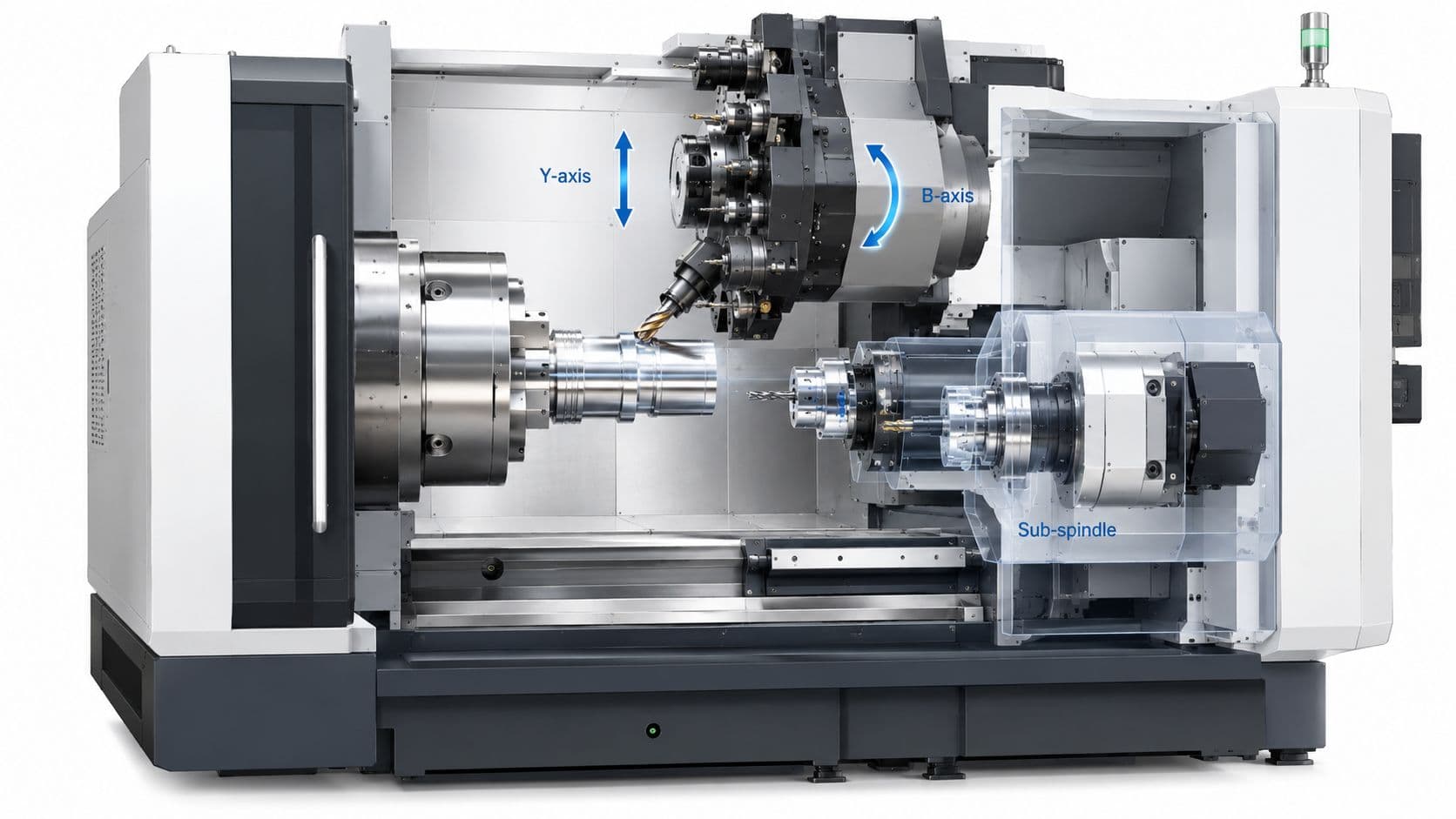
CNC is often the best first production process for low-volume hardware. It avoids tooling lead time, holds predictable tolerances, and lets teams revise geometry between builds without scrapping a mold. It also gets expensive fast if the part ignores cutter access, tool rigidity, or setup count.
Use these rules early:
- Keep minimum features practical. Tiny slots, thin walls, and small internal radii force small cutters, slower feeds, and longer cycle times.
- Avoid deep, narrow pockets. As cavity depth grows relative to width, tools deflect more, finishes get worse, and quoting gets less friendly.
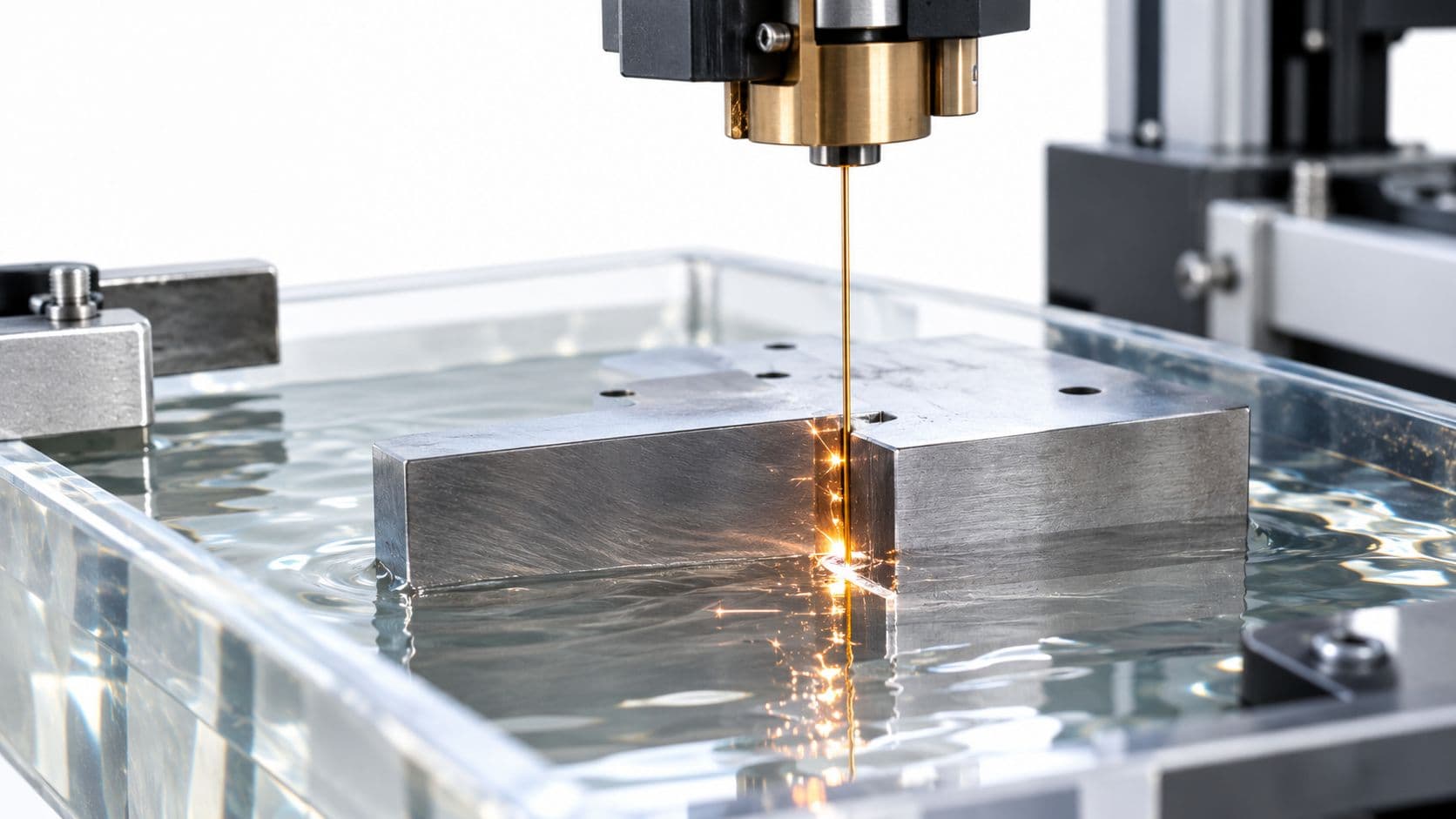
- Add internal radii where tools need them. Square internal corners usually trigger corner reliefs, EDM, or a design-change request.
- Reduce setups. Every flip adds labor, fixturing effort, and tolerance stack risk.
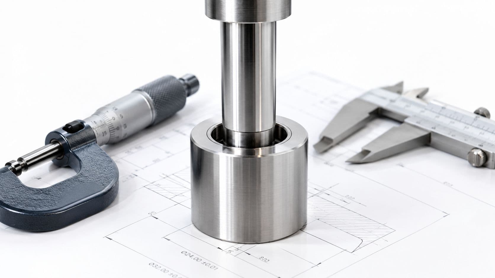
- Call out precision only where function needs it. Tight tolerances on non-critical faces waste machine time and inspection time.
For runs in the tens or low hundreds, CNC often wins because the part can change after test data comes in. That flexibility has real value during NPI. I have seen teams save a program by accepting a slightly larger inside radius and one visible tool-access feature, because that change cut machining time enough to keep pilot quantities on schedule.
CNC is a poor fit if the design depends on thin living features, highly organic enclosed geometry, or molded cosmetics that would take excessive surfacing and hand finishing to match.
Injection molding
Injection molding pays off when the geometry is stable enough to justify tooling and the part is designed around flow, cooling, and ejection instead of around a machined prototype. In low-volume programs, that distinction matters. A part that is technically moldable can still be the wrong business decision if the tool is expensive to modify and the design is not settled.
Focus on the features that drive cost and tool complexity:
- Add draft to pull faces. Zero-draft walls increase ejection force and create cosmetic risk.
- Keep wall thickness as uniform as the design allows. Sudden thick sections raise the odds of sink, warp, and long cooling time.
- Remove undercuts unless they solve a real product problem. Side actions and lifters raise tool cost and add failure points.
- Choose a practical parting line. A perfect cosmetic split often costs more than the market will reward.
- Use ribs and gussets with restraint. They add stiffness efficiently, but oversized ribs print through and create sink.
Teams evaluating resin and tooling options can use this guide to injection molding thermoplastics to compare material behavior against product needs.
Low-volume molding has different priorities
A startup building 500 housings does not need the same mold strategy as a consumer product heading to 500,000 units. The tool should support learning, controlled revisions, and acceptable part quality at a sane upfront cost.
That often means accepting trade-offs such as a simpler shutoff, less cosmetic perfection on hidden surfaces, or a two-part assembly instead of one aggressive molded part. Unit cost may be higher, but total program cost can be lower because the tool is cheaper, faster to cut, and easier to revise after pilot feedback.
3D printing SLA and SLS
SLA and SLS are useful DFM tools when the team is honest about what each process proves. Printed parts can validate fit, access, assembly sequence, and industrial design intent. They do not automatically prove that the same geometry will machine cleanly or mold well.
For practical low-volume work:
- Use SLA for visual models and fine detail. Surface quality is good, but material behavior can mislead teams if the production part will be tough, flexible, or heat-exposed.
- Use SLS for functional prototypes and complex internal geometry. It handles enclosed features better and usually needs less support planning than resin printing.
- Set part orientation on purpose. Orientation changes surface finish, strength on loaded features, support marks, and dimensional stability.
- Avoid fragile pins, knife edges, and thin unsupported tabs. A feature that survives the print may still fail during handling or assembly.
- Treat additive geometry with caution if the production path is CNC or molding. Lattice structures, trapped voids, and highly organic transitions may be cheap to print and expensive to make any other way.
Printed parts help teams learn fast. They hurt teams when a prototype gets approved because it printed well, then has to be redesigned under deadline pressure for the actual production process.
Sheet metal fabrication
Sheet metal is one of the best low-volume options for enclosures, brackets, and internal frames. It moves quickly, changes quickly, and avoids molding investment while the product architecture is still settling. The mistakes usually show up at bends, hardware locations, and assembly access.
Design around the shop floor, not just the outer shape:
- Keep bend strategy consistent. Mixed bend directions and crowded flange geometry slow forming and increase variation.
- Keep holes and cutouts away from bend zones. Features placed too close to bends distort or require process concessions.
- Standardize radii, hardware, and stock thickness. Fewer variables simplify setup and sourcing.
- Use common material gauges and available tooling. Unusual combinations create procurement and fabrication delays.
- Plan assembly hardware early. PEM inserts, tabs, welds, and screws each need different spacing and access.
For many products in the 50 to 2,000 unit range, sheet metal beats molded plastic because it can absorb design churn without a tooling restart.
Vacuum casting
Vacuum casting is a useful bridge process for low-volume housings and appearance parts when teams want something closer to molded plastic than a typical printed prototype. It works best when the design respects silicone tooling limits and realistic variation.
Use it well by following a few rules:
- Design for demolding. Severe undercuts and delicate features reduce tool life and consistency.
- Keep walls and support features sensible. Thin sections can warp or sag.
- Reserve tight tolerances for features that need them. Soft tooling is not the place to force production-grade precision across the whole part.
- Use it as a bridge, not a long-term substitute for a settled production plan. Once demand stabilizes, the economics usually shift toward a harder production process.
Vacuum casting is strong for market tests, short cosmetic runs, and pre-production builds. It becomes a liability when teams try to stretch it into a stable production system after volumes and quality expectations increase.
DFM quick reference by manufacturing process
| Process | Key DFM Consideration | Recommended Value | Reason |
|---|---|---|---|
| CNC machining | Minimum feature size | Keep features large enough for practical cutter access | Reduces cycle time, tool deflection, and scrap risk |
| CNC machining | Internal cavity depth-to-width | Avoid deep, narrow pockets | Improves finish, stability, and machining efficiency |
| Injection molding | Draft angle | Include draft on pull surfaces | Improves ejection and reduces tooling wear |
| 3D printing SLA and SLS | Minimum wall thickness | Follow process and material limits from your supplier | Prevents fragile walls and print failure |
| 3D printing SLA and SLS | Self-supporting angle | Favor geometry that reduces supports | Cuts post-processing time and surface damage |
| Cross-process tolerance strategy | Tight tolerance threshold | Apply only to critical interfaces | Slows production and increases inspection cost |
| Cross-process tolerance strategy | Non-critical interface tolerance | Use the loosest tolerance the function allows | Reduces rework and improves yield |
Common DFM Pitfalls and How to Avoid Them

A startup team approves a prototype enclosure on Friday. It looks right, fits the board, and photographs well for the investor update. By Monday, the supplier comes back with three problems. The inside corners are too tight for practical CNC tooling, the snap features are risky for molding, and the tolerances are tighter than the assembly needs. Nothing is wrong with the product idea. The part just was not designed for the way it will be made at 50, 500, or 2,000 units.
That pattern is common in rapid prototyping and low-volume production. Teams move fast, freeze details late, and switch processes between prototype rounds and early builds. The result is usually not a catastrophic failure. It is schedule slip, extra machining hours, avoidable tooling edits, and quality variation that should have been designed out earlier.
Designing in a silo
Siloed decisions create expensive surprises.
A mechanical designer may optimize the model for appearance and packaging. A sourcing lead may optimize for available vendors and lead time. A manufacturing engineer looks at cutter reach, fixture access, mold parting, support removal, and inspection method. If those views do not meet early, the part gets revised one constraint at a time.
For low-volume programs, this hurts more than many teams expect. At 100,000 units, a tooling change may be justified by long-term savings. At 200 units, the same change can wipe out the margin on the build. Early DFM reviews should happen while geometry is still flexible, especially for enclosure splits, wall strategy, fastening method, and tolerance stack decisions.
A short cross-functional review before design release usually saves more time than a week of quote revisions.
Over-tolerancing every feature
Teams often tighten everything because they do not yet know what will matter in test, assembly, or customer use. That instinct is understandable. It also drives cost fast.
On a CNC part, tighter tolerances can mean slower feeds, extra finishing passes, better workholding, and more inspection. On molded parts, they can force tool adjustments and tougher process control. On printed parts, they can create inspection arguments around a process that was never meant to hold precision across every surface.
Use tolerance where function demands it. Datums, bearing fits, sealing faces, connector locations, and mating features deserve attention. Cosmetic walls, non-locating outer surfaces, and clearance features usually do not need the same treatment.
A practical rule is simple. If a feature does not align, seal, carry load, or control assembly, do not tolerance it like a critical interface.
Choosing the wrong process for the stage
A part can be manufacturable and still be wrong for the program.
I see this when teams use SLA to validate snap fits that will later be molded in polypropylene, or machine aluminum housings that are eventually expected to behave like molded ABS parts. The prototype answers one question, then creates confidence about three others that were never tested.
For builds in the 10 to 5,000 unit range, process choice is a trade-off between speed, change cost, unit price, and how closely the part represents production intent. CNC gives strong dimensional control and fast iteration, but complex geometry can become expensive quickly. Urethane casting can produce good cosmetic samples and short runs, but consistency and tool life limit how far it scales. 3D printing is excellent for fit checks and early iteration, but post-processing, anisotropy, and surface variation can distort what the team learns.
Choose the process based on the decision you need to make next, not just on what worked on the last project.
Designing a prototype that cannot mature into production
This pitfall is easy to miss in NPI work. The first prototype is often approved on speed alone, then the team discovers that every feature needs to be remodeled for the pilot run.
Examples are common. A CNC prototype may use sharp internal corners that require radii in production. A printed part may rely on thick solid sections that would sink in molding. A cosmetic prototype may hide assembly strategy because it was bonded together instead of fastened. Each shortcut may be reasonable by itself. The problem starts when nobody marks it as temporary.
The fix is to separate prototype-only features from production-intent features in the design review. If a geometry choice exists only to get parts in hand quickly, document it and assign the trigger for replacing it.
Ignoring assembly and inspection until the end
A part can quote cleanly and still fail on the bench.
Low-volume builds often use manual assembly, simple fixtures, and flexible inspection methods. That changes what good DFM looks like. A feature that is easy to machine may still be hard to align during assembly. A housing split that looks clean in CAD may force awkward cable routing or make torque access difficult. A tolerance scheme may be acceptable on individual parts but create stack-up problems once the first ten assemblies are built.
Check three things before release:
- How the operator will hold, align, and fasten the part
- Which dimensions need to be inspected, and with what method
- Where variation can accumulate across the full assembly, not just one component
That review matters just as much for a 50-unit pilot as for a larger launch. In low-volume manufacturing, labor content is high, so every awkward manual step shows up directly in cost and throughput.
Treating DFM as a late-stage cleanup task
Late DFM usually becomes redesign.
Once the CAD is released, purchase orders are pending, and test dates are booked, teams become reluctant to change geometry even when the manufacturing risk is obvious. Then they spend more time managing exceptions than fixing the root cause. Shops add notes to the traveler. Inspectors sort borderline parts. Assemblers rework what should have fit the first time.
The better approach is simple. Run DFM checks at concept, before quote, and again before release. That cadence catches different problems at different stages and fits the reality of prototype-to-pilot programs, where the right answer at 20 units may not be the right answer at 2,000.
Good DFM is not about making the design less ambitious. It is about choosing where to spend complexity so the part can be built, assembled, and changed without wasting time or money.
Collaborating with Your Manufacturing Partner for DFM

DFM is collaborative by nature. A design engineer understands intent. A manufacturing partner understands what that intent looks like in fixtures, cutters, mold steel, support structures, and inspection workflows. You need both views early.
Send a quote-ready package
A lot of avoidable back-and-forth starts with incomplete RFQ packages.
For most mechanical parts, a strong package includes:
- A clean 3D model in a neutral format such as STEP, plus native CAD if helpful
- 2D drawings for features that require controlled dimensions or GD&T
- Material callout with any approved alternatives if function allows
- Finish requirements split into cosmetic and functional needs
- Quantity context so the supplier can advise on process fit
- Assembly notes if mating parts or stack-ups matter
If the file set doesn't tell the manufacturer what matters, they'll either quote conservatively or ask you to clarify. Both cost time.
Read DFM feedback like engineering input
Some teams treat supplier comments as objections. That's the wrong framing. Good DFM feedback is free process knowledge attached to your part.
If a manufacturer suggests larger internal radii, simpler shutoffs, looser non-critical tolerances, or a revised parting line, don't read that as resistance. Read it as a map of what is causing cost or risk.
Useful questions to ask back:
- Which features are driving complexity most?
- Can we change this without affecting function?
- Is the issue tooling, cycle time, fixturing, or inspection?
- What would you do differently for 50 units versus 2,000 units?
Those answers often reveal design options your internal team didn't consider.
Use one partner across prototype and NPI when possible
When prototype suppliers and production suppliers are disconnected, design intent gets lost in handoff. The prototype may prove fit and function, but not in a way that helps the next manufacturing stage.
A partner that can support CNC machining, 3D printing, molding, sheet metal, and inspection in one workflow usually gives better continuity. They can tell you whether your prototype strategy is helping the eventual build or teaching the wrong lessons.
The most valuable supplier feedback usually sounds specific, not polished. It points to one face, one radius, one tolerance zone, one gate location, one assembly interference.
That's the kind of collaboration that reduces surprises.
Your Next Steps to Implementing DFM Today
You don't need a new department to start using DFM. You need a tighter review habit. If your team can catch manufacturability issues before RFQ, you'll prevent a large share of the delays and quote shocks that slow hardware programs down.

A practical design review checklist
Use this on your next part or assembly review:
- Check the actual build quantity: Don't default to mass-production rules if the actual need is a short run.
- Match each part to a likely process: CNC, molding, sheet metal, SLA, SLS, or vacuum casting should be chosen intentionally.
- Remove non-functional complexity: Deep pockets, trapped corners, undercuts, and decorative geometry should justify themselves.
- Standardize hardware: Reduce unique screw types, inserts, and purchased components where possible.
- Review tolerances by function: Tighten only the surfaces that locate, seal, align, or directly affect performance.
- Inspect assembly access: Make sure tools can reach fasteners and parts install in a repeatable sequence.
- Validate with physical prototypes: Build the part in a way that teaches something useful about the likely production path.
If your team is moving through early builds, this guide to rapid prototyping for 2026 is a helpful next read for choosing the right validation path.
The short version of what is design for manufacturability is this. It's designing with the machine, the operator, the toolmaker, the buyer, and the inspector in mind before they're forced to solve the problem for you later.
If you want a practical read on your actual part, FIRMFG can help you move from CAD to buildable hardware with fast quoting, prototype-to-production process support, and DFM feedback grounded in CNC machining, molding, sheet metal, 3D printing, and low-volume manufacturing.