Learn the what, why, and how of dimensional inspection. This guide covers CMM, laser scanning, standards, and best practices for tight-tolerance CNC parts.
You released the drawing. The CAD looks clean, the stack-up closes, and the supplier says the part is in spec. Then the first build arrives and something still doesn't fit. A dowel hole is slightly off relative to a datum face. A cover sits proud on one corner. A shaft that should slide in binds halfway. At that point, the problem usually isn't “inspection happened” or “inspection didn't happen.” Instead, the issue is that the wrong thing was measured, the wrong method was used, or the result was treated as a simple pass/fail call when the measurement itself carried uncertainty.
That's where dimensional inspection stops being paperwork and becomes engineering. It's the discipline that connects design intent to the physical part on the bench. If you're designing tight-tolerance CNC parts, prototypes for fit checks, or low-volume production hardware, you need to understand not just what was measured, but how it was measured, what reference frame was used, and how much trust you can place in the result.
Table of Contents
- Inspection is the bridge between CAD and reality
- Manual tools still have a place
- When scanning is the better answer
- Standards remove interpretation drift
- What a useful report should show
- Before the first chip is cut
- During machining and first article
- Final verification before shipment
- Why two valid methods can disagree
- Drawing problems become inspection problems
- How the quality flow works in practice
- Choosing the method for the feature
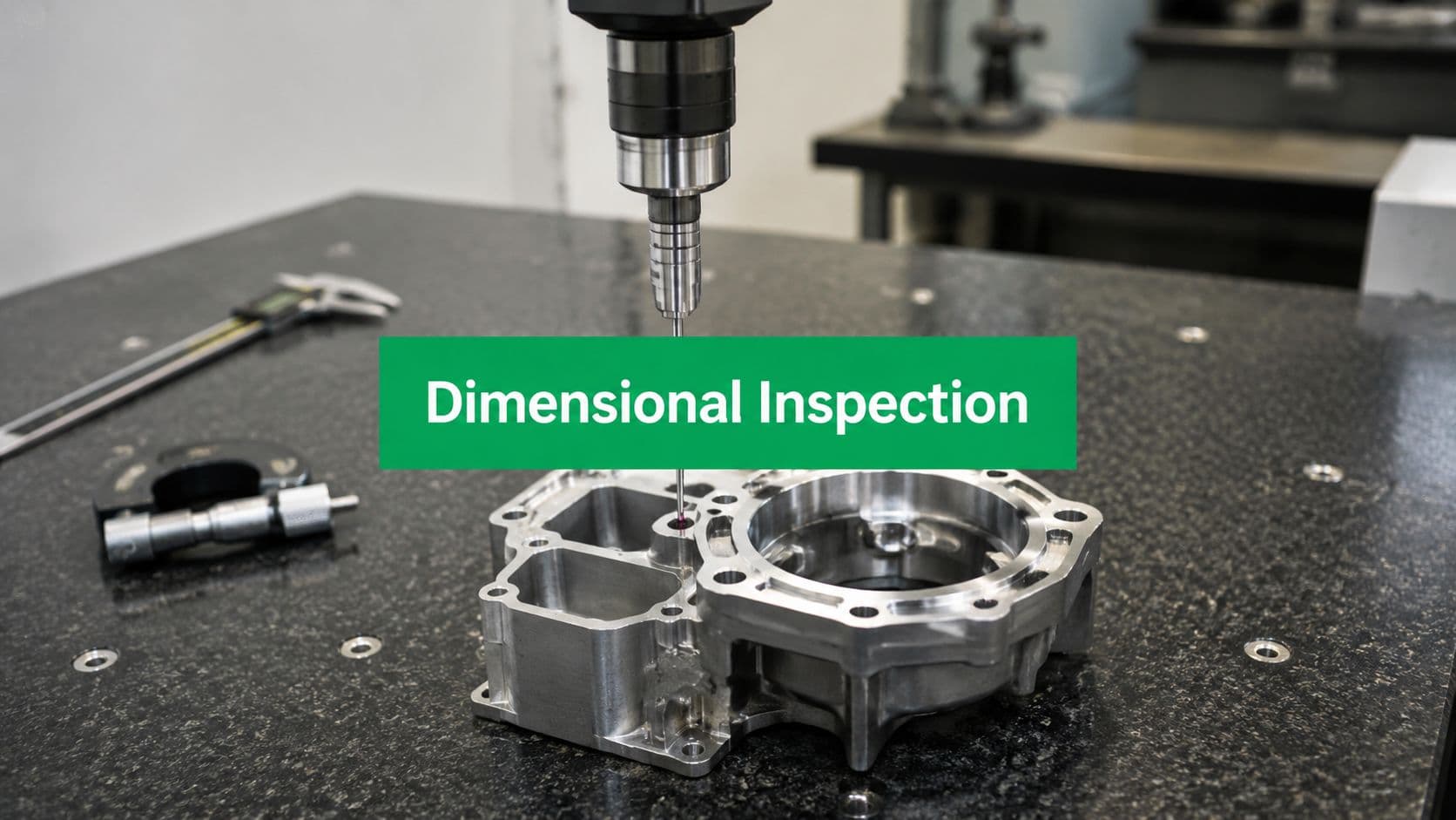
What Is Dimensional Inspection and Why Does It Matter
Dimensional inspection is the process of measuring a manufactured part and comparing those results against the engineering drawing, CAD model, and tolerance requirements. In plain terms, it answers one question: did the physical part come out the way the design intended?
That sounds straightforward until assembly proves otherwise. Parts can meet a few headline dimensions and still fail functionally because location, orientation, profile, or datum relationships weren't verified correctly. Good dimensional inspection catches those issues before the part reaches assembly, validation, or a customer.

Inspection is the bridge between CAD and reality
Design engineers work in ideal geometry. Machinists work in material, fixturing, tool deflection, thermal change, and machine behavior. Inspection is the control point between those worlds.
A serious inspection process confirms more than size. It checks whether critical features exist in the right place, relative to the right datums, with enough confidence to support the function of the part. That matters most when the part has to mate with other components, seal, rotate, align optically, or locate repeatably during assembly.
Historically, this discipline grew far beyond simple bench checks. NIST's Dimensional Measurement Services program exists to provide high-accuracy length based calibrations that support global trade, which shows how dimensional inspection became tied to measurement traceability and standardized quality systems, not just operator judgment.
Why the tool choice matters
One of the most practical rules in metrology is the ten times better guideline. The measuring equipment should be 10× more accurate than the tolerance being checked, as described in this technical overview of dimensional inspection. That's not a preference. It's a capability requirement.
If you're checking a loose external dimension on a prototype bracket, calipers may be fine. If you're evaluating true position, profile, or a tight hole pattern on a precision component, they're often the wrong tool entirely.
**Practical rule:** If the inspection method is too close to the tolerance band, the result may look precise while telling you very little.
That's why dimensional inspection matters to design engineers. It protects fit, function, reliability, and rework cost. It also reveals whether a nonconformance is real, or whether you're looking at the limit of the measurement method instead of the limit of the part.
The Metrologist Toolbox Comparing Inspection Methods
Different inspection methods answer different questions. Engineers often ask, “What's the most accurate tool?” The better question is, “What tool gives the most trustworthy answer for this feature, at this tolerance, under these setup conditions?”
A common metrology rule is to keep measurement uncertainty at roughly 10% or less of the tolerance, otherwise false accepts and false rejects rise and capability data becomes less reliable, as noted in this dimensional inspection guidance. That's why method selection has to start with the tolerance band, not with whatever instrument happens to be nearby.
Manual tools still have a place
Calipers, micrometers, height gauges, gauge pins, and dial indicators remain useful because they're fast, accessible, and effective for straightforward features.
They work well for:
- Basic size checks: Outside diameters, thicknesses, slot widths, and simple step dimensions.
- Shop-floor feedback: Quick verification during setup or after a tool change.
- Lower-risk features: Dimensions that don't control assembly alignment or sealing performance.
They don't work well for:
- Complex GD&T callouts: True position, profile, perpendicularity, and datum-driven relationships.
- Freeform surfaces: Contours and blends that need full-surface comparison.
- Ambiguous contact geometry: Soft edges, chamfers, small radii, or hard-to-access features.
Where CMMs earn their keep
A coordinate measuring machine (CMM) probes points in a controlled coordinate system and evaluates features relative to established datums. This is usually the right choice for precision prismatic parts with meaningful GD&T.
Use a CMM when you need:
- Datum-based measurement: The report must reflect how the drawing defines the part.
- Feature relationships: Hole-to-hole location, flatness, parallelism, or positional tolerance.
- Traceable reporting: You need a formal inspection record you can review feature by feature.
Portable CMMs and articulated arms sit between bench tools and fixed CMMs. They're helpful for larger parts, faster access, and on-machine checks, but they're more sensitive to operator technique and environmental setup.
When scanning is the better answer
Laser scanners and structured-light systems capture dense point clouds or meshes. They shine when the question is about overall form, surface deviation, cast or molded geometry, or rapid comparison to a CAD surface.
They're especially useful for:
- Organic or sculpted shapes
- Fast whole-part visualization
- Form and fit reviews on prototypes
- Finding where material moved, not just whether one dimension drifted
Their limitation is that “more data” doesn't always mean “better answer.” Surface finish, reflectivity, edge definition, line-of-sight issues, and alignment strategy all affect the result.
For engineers working through tolerance decisions, this guide to CNC machining tolerances is a useful companion to inspection planning because it helps you separate dimensions that need true metrology from those that only need practical process control.
| Method | Typical Accuracy | Best For | Primary Limitation |
|---|---|---|---|
| Manual tools | Depends on tool selection and operator use | Simple size checks and fast in-process verification | Weak for GD&T and feature relationships |
| Fixed CMM | High precision for tight-tolerance work | Datum-based inspection and formal reports | Slower setup and programming |
| 3D laser scanner | Best treated as high-density comparative data | Complex surfaces and full-form analysis | Sensitive to surface condition and alignment |
| Portable CMM arm | Flexible access for larger or awkward parts | Shop-floor inspection and moderate-complexity geometry | More operator and setup dependent |
If a feature controls assembly, don't choose the inspection method for convenience. Choose it for how the feature functions.
The Rules of the Game Key Standards and Reporting
A part can be machined well and still produce a bad inspection result if the drawing language is vague. Most shop disputes don't start with bad intent. They start with different interpretations of the same requirement.
Standards remove interpretation drift
Standards provide the grammar for dimensional inspection. They define how datums are established, how geometric controls are interpreted, and how measurements should relate back to design intent. Without that shared grammar, two competent people can inspect the same part and reach different conclusions for reasons that have nothing to do with manufacturing quality.
The movement toward standardized, traceable measurement systems is part of why dimensional inspection became a mature discipline. NIST's calibration role shows that the industry depends on a trusted measurement backbone, not just local shop practice. That's the foundation behind consistent reporting across suppliers, customers, and regulated industries.
For engineers who need a refresher on drawing language, this overview of geometric dimensioning and tolerancing is useful because it ties the symbols back to what inspectors evaluate.

What a useful report should show
A good inspection report does more than list green and red cells. It shows the logic of the measurement.
Look for these elements:
- Feature identification: Each result should map cleanly to a drawing balloon, note, or CAD feature.
- Nominal and actual values: You need the target and the measured result, not just a status flag.
- Datum reference: For geometric controls, the report should reflect the correct datum structure.
- Clear disposition: Pass, fail, or hold for review should be visible and unambiguous.
- Method context: CMM, manual gauge, scanner, or comparator should be known to the reader.
A formal first article report is especially valuable because it verifies that the manufacturing and inspection setup can reproduce the design intent before larger batches move forward.
Reports are only as useful as the setup behind them. If the datum scheme in the report doesn't match the drawing, the numbers may be neat and still be wrong.
Sampling also needs engineering judgment. Some features deserve focused attention on every part. Others can be monitored through a defined control plan. The key is to inspect according to risk and function, not habit.
Inspection in Action A Prototyping and Production Workflow
Inspection works best when it's distributed through the job, not postponed until the end. Waiting until final inspection to learn that the process drifted is how good material turns into scrap and delivery dates start sliding.

Before the first chip is cut
The inspection story begins during DFM review. That's where an experienced team looks at the drawing and asks practical questions.
- Which features are critical to function: A sealing diameter, bearing bore, hole pattern, or datum face may need a higher-confidence measurement method.
- Which callouts are likely to cause confusion: Mixed datum logic, incomplete GD&T, or dimensions that don't align with the part's physical setup need clarification early.
- Which surfaces can be measured: Deep pockets, small undercuts, and narrow walls may require a specific probing or scanning strategy.
At this stage, good teams also decide what must be verified in process versus what can wait for a final report.
During machining and first article
Once production starts, in-process checks keep the process honest. Machinists and inspectors verify stock condition, setup references, tool wear effects, and feature size before the entire run drifts.
That usually means a mix of methods. A micrometer may be enough to control a turned diameter during the run. A height gauge might confirm a step. A CMM program may be reserved for the first article or for the features that drive assembly risk.
The first article inspection matters because it tests the full manufacturing system, not just one dimension. It tells you whether the setup, program, fixturing, offsets, and inspection method are all aligned.
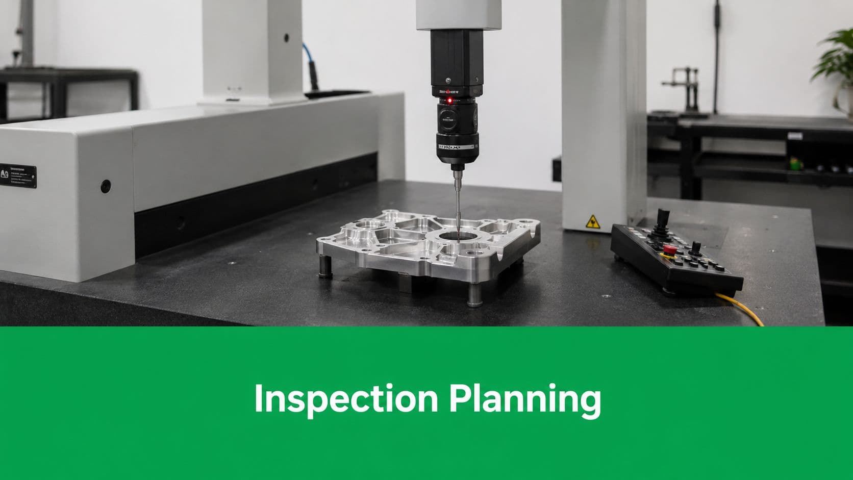
For engineers planning how to structure these checkpoints, this overview of inspection planning is useful because it frames inspection as part of the manufacturing workflow rather than a final audit.
Final verification before shipment
Final inspection should confirm the part, not discover the process. By this point, the team should already understand how the part behaves.
A strong final verification flow usually includes:
- Visual and handling checks: Burrs, edge breaks, obvious damage, and surface issues.
- Critical feature confirmation: The dimensions and GD&T controls that affect fit and function.
- Report generation: Traceable documentation tied to the drawing revision.
- Disposition review: Any borderline or questionable result gets engineering attention before release.
A prototype job may lean heavily on fit-critical checks and form comparison. A production job may emphasize repeatability, revision control, and documented release criteria. The sequence changes by product, but the principle doesn't. Inspection is most effective when it prevents surprises instead of documenting them after the fact.
Common Pitfalls in Dimensional Inspection and How to Avoid Them
The most common mistake in dimensional inspection is treating every result as binary. Engineers see a value outside tolerance and assume the part is bad. They see a value inside tolerance and assume the part is good. In tight-tolerance work, that can be a costly simplification.
The pass fail trap
A major gap in most introductory inspection content is measurement uncertainty and disagreement between methods. As noted in this discussion of dimensional inspection gaps, most guidance explains comparison to CAD or tolerances but doesn't explain how much error the method itself adds, or when two correct methods can disagree.
That matters most on borderline results. If the feature is near a limit, the decision depends on more than the displayed number. It depends on probe size, contact force, alignment strategy, scanning resolution, fixture stability, temperature, and the way the feature is mathematically constructed.
A borderline measurement is not just a number. It's a number plus a method.
Why two valid methods can disagree
A caliper measures what its jaws can physically contact. A CMM evaluates points in a datum-based coordinate system. A scanner compares a cloud or mesh to a CAD surface after alignment. Those are not interchangeable activities.
Two methods can disagree because they:
- Reference different datums: One setup may float the part while another constrains it correctly.
- Sample geometry differently: A few contact points won't tell the same story as dense scanned data.
- Handle edges differently: Chamfers, blends, burrs, and radius transitions can distort practical pick points.
- React differently to surface condition: Reflective, rough, soft, or coated surfaces change results.
This is why engineers should ask not only “What did it measure?” but also “How was the part aligned, and what exactly was the software evaluating?”
Drawing problems become inspection problems
Inspection can't rescue a vague drawing. If a feature is critical, define it in a way that supports repeatable measurement. That often means establishing sensible datums, avoiding contradictory dimensions, and identifying the difference between a cosmetic dimension and a functional one.
Common failure modes include:
- Using simple size dimensions where GD&T is needed
- Choosing datums that don't match how the part assembles
- Calling out tight tolerances on features that have no functional reason to be tight
- Reviewing the report without reviewing the method
The fix is collaborative. Designers, machinists, and inspectors should agree on the measurement strategy before the part is cut when the drawing has tight positional, profile, or form requirements.
How LC Proto Guarantees Quality with Precision Inspection
A capable supplier doesn't separate machining from inspection. The two have to reinforce each other. That's especially true when parts are complex, tolerances are tight, and the first build needs to be useful for engineering decisions instead of just “close enough.”

How the quality flow works in practice
LC Proto starts projects with a DFM review, which is the right place to catch inspection risk before production starts. A drawing may be manufacturable in a general sense but still difficult to inspect reliably if datums are unclear or if a critical feature can only be reached with a limited probing approach.
From there, the quality flow is built around:
- Process-aware inspection: In-process checks on the shop floor catch drift while there's still time to correct it.
- Formal final verification: Critical dimensions and geometry are checked before release.
- Advanced metrology when needed: CMMs and laser scanning are used for features that can't be trusted to manual checks alone.
- Traceable quality control: The company operates within an ISO 9001-certified system, which is important for revision control, documentation discipline, and repeatable inspection practice.
This matters for both prototypes and low-volume production. A prototype part isn't valuable just because it arrives quickly. It's valuable when the measurements behind it are trustworthy enough to guide the next design decision.
Choosing the method for the feature
The strongest part of a mature inspection workflow is method selection. Not every feature needs the same approach.
For example:
- Medical or high-traceability components: CMM inspection is often the practical choice for tight datum-driven geometry because it supports detailed, feature-level reporting.
- Automotive prototype housings or covers: 3D scanning can be a better fit when engineers need fast feedback on overall form, contour, and assembly interaction.
- General machined hardware: Manual tools still make sense for noncritical features where speed and direct shop feedback are more valuable than full metrology overhead.
That kind of split approach is what prevents overinspection on one side and false confidence on the other. If you're evaluating suppliers for demanding parts, the useful question isn't whether they “do inspection.” It's whether they can explain which method they'll use for your critical features, how they'll establish datums, and what confidence level you should attach to the result.
Actionable Takeaways for Your Next CNC Project
If you want dimensional inspection to protect your design instead of merely documenting problems, make a few decisions early.
- Define critical-to-function features clearly: Don't leave assembly-driving geometry buried in a crowded drawing.
- Match the method to the tolerance: Keep the 10× better rule in mind when discussing how a supplier will verify tight features. If the inspection system isn't substantially better than the tolerance band, confidence drops.
- Ask about datums, not just dimensions: A hole location only means something relative to the correct reference scheme.
- Treat borderline results carefully: When a measurement is close to the limit, review uncertainty and method before rejecting the part.
- Use first article results as engineering feedback: A strong FAI tells you how the entire process behaves, not just whether one sample happened to pass.
- Choose a manufacturer that can explain the metrology plan: Clear communication on measurement strategy is a quality advantage, not an administrative extra.
Dimensional inspection is where design intent meets physical evidence. When the drawing is clear, the method fits the feature, and the team respects measurement uncertainty, inspection becomes one of the fastest ways to reduce risk in CNC projects.