Robotics Prototyping: Methods, Workflows, and Costs
You've got a bench demo that looks good in a clean lab, the code runs, the arm moves, the intake grabs parts, and everyone feels close. Then the practical questions show up, like whether that bracket survives vibration, whether the sensor mount drifts after three cycles, and whether the assembly still fits after paint, fasteners, and wiring get added. That's where robotics prototyping stops being a sketching exercise and becomes a manufacturing problem with software attached.
The market around that problem is already large and still expanding. One industry estimate places the robotics prototyping market at USD 2.9 billion in 2024, with a projection of USD 5.3 billion by 2030 at a 10.4% CAGR, while another estimates USD 4.4735 billion in 2025 and projects USD 10.1144 billion by 2035 at an 8.5% CAGR (strategicmarketresearch.com). That scale reflects a simple reality, robotics teams aren't just buying parts, they're buying iterations, validation, and the right to be wrong early.
Table of Contents
- Why Robotics Prototyping Is the Hard Part
The real bridge is from concept to validated hardware
Why the loop gets expensive fast
The Core Prototyping Methods Explained- CNC machining for tight features and structural parts
- Industrial 3D printing for fast iteration and geometry freedom
- Sheet metal for chassis, enclosures, and brackets
- Rapid tooling and injection molding for bridge runs
- Vacuum casting for small runs and appearance models
How to Choose the Right Process for the Part- Start with the feature that actually matters
Materials, Tolerances, and DFM Decisions- Match material behavior to the robot's job
From Prototype to Pilot Production- Where the time and money actually go
Testing and Validation Practices That Actually Work- Layer the tests instead of jumping straight to field trials
Compliance and Industry-Specific Requirements- Medical, automotive, and industrial builds ask for different proof
Vendor Selection and Bridge-to-Production Checklist- What to check before you hand over a robot assembly
Why Robotics Prototyping Is the Hard Part
The hardest prototype is usually the one that already works on a bench. A team gets a mechanism moving, then discovers the environment is uglier, with vibration, dust, wiring strain, EMI, alignment drift, and a safety review that cares less about motion and more about repeatability. A demo proves intent, but a robot prototype has to prove it can survive integration.
The real bridge is from concept to validated hardware
That bridge matters because industrial robotics is no longer a niche experiment. The International Federation of Robotics reported 542,000 industrial robots installed worldwide in 2024, more than double the annual installation level from 10 years earlier, with annual installations above 500,000 for four consecutive years and an operational stock of 4,663,698 units in 2024, up 9% year over year (IFR summary). In other words, the prototype phase is feeding a very real production pipeline, not a lab curiosity.
Practical rule: the first part out of a machine is not the milestone. The first part that assembles cleanly, carries load, routes cables, passes the sensor check, and survives the second test cycle is the milestone.
Why the loop gets expensive fast
Robotics is a stack of coupled systems. Mechanics affect sensor placement. Sensor placement affects control tuning. Control tuning changes load paths. Once those pieces start interacting, every change ripples through the build. That's why the cheapest schedule compression usually comes from front-loaded digital validation, not from rushing metal out of the machine.
A useful way to think about it is this, the prototype isn't one object, it's a build-test-fix loop. The loop includes CAD, DFM feedback, simulation, additively printed first articles, machined functional parts, integration, and then another round of testing. If any one of those steps is skipped, the team usually pays for it later in rework, alignment fixes, or software hacks that never quite become production-friendly.
The Core Prototyping Methods Explained

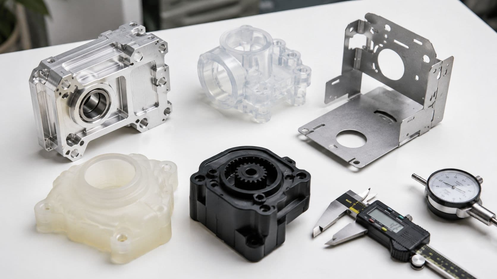
Each process does a different job in a robot build. The mistake is treating them as interchangeable, because a sensor bracket, a gear housing, a cosmetic shell, and a chassis rail all punish different weaknesses. The right choice depends on whether the part has to look right, fit right, carry load, or arrive fast enough to keep the program moving.
CNC machining for tight features and structural parts
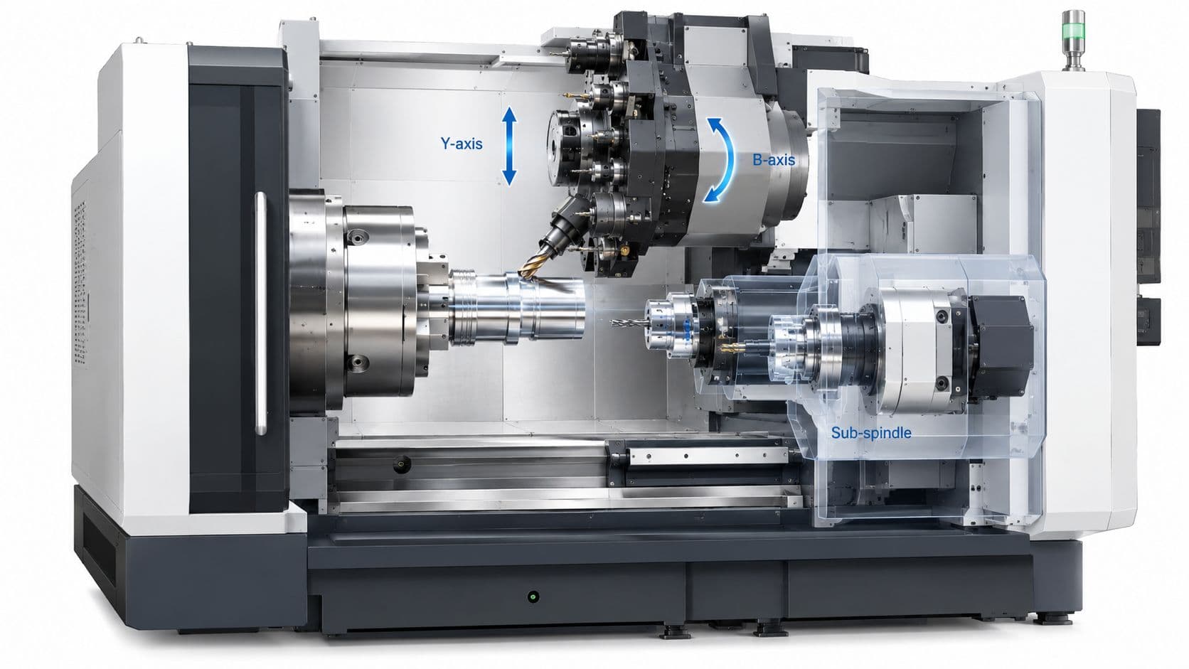
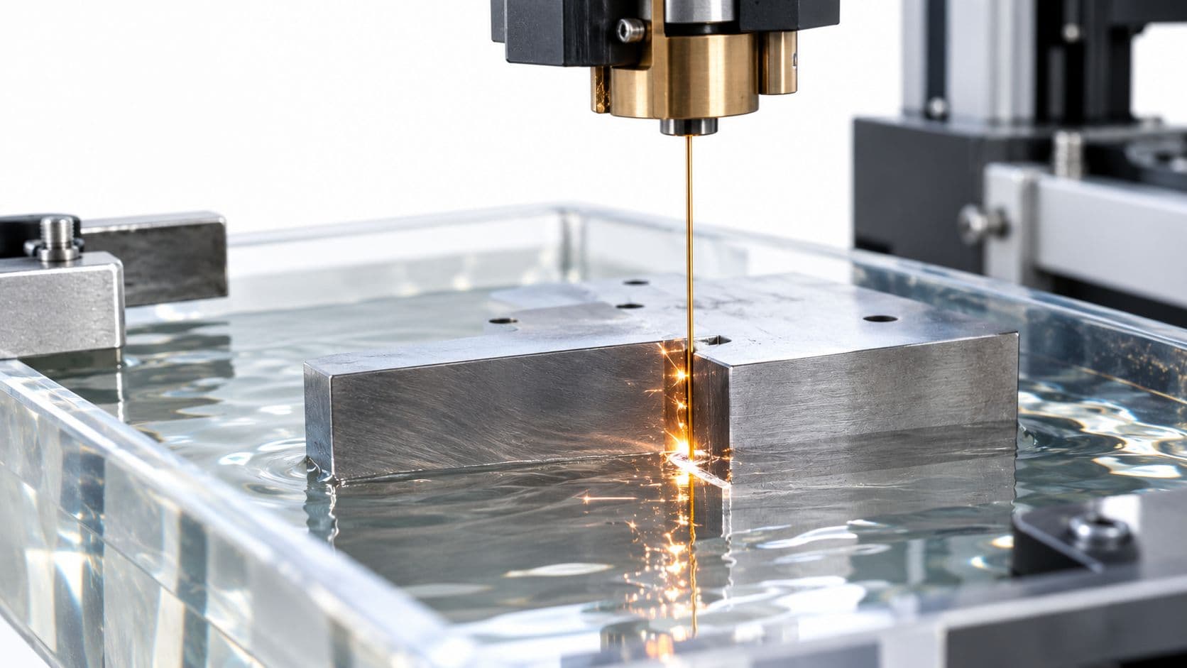
CNC machining, including 3-axis, 4-axis, 5-axis milling, turning, micro machining, and wire EDM, is the workhorse for parts that need reliable mating faces and stronger materials. It suits motor mounts, bearing seats, actuator housings, brackets, rail interfaces, and structural links because the process removes material from a known blank and gives you stable geometry in metal or engineering plastic. The limitation is simple, complex internal forms are harder and setup time rises as the part gets trickier.
Industrial 3D printing for fast iteration and geometry freedom
Industrial SLA, SLS, FDM, and metal printing are useful when the part needs speed or shape complexity more than brute strength. SLA is a strong choice for cosmetic shells, sensor covers, and tight visual prototypes, while SLS and FDM are often used for ducts, clips, housings, and functional shapes that would be awkward or expensive to machine. The trade-off is that printed parts often need more attention on anisotropy, surface quality, and hole accuracy than teams expect on the first pass.
Sheet metal for chassis, enclosures, and brackets
Laser cutting, bending, stamping, and welding make sense for frames, guards, covers, and support structures that live in sheet form anyway. A robot chassis frame, battery tray, or sensor mast often belongs here because sheet metal delivers stiffness efficiently and moves fast once the geometry is settled. The downside is that early design mistakes, especially around bend relief, hole spacing, and flange access, can turn into expensive revision churn.
Rapid tooling and injection molding for bridge runs
Injection molding with rapid tooling is where a prototype starts acting like a future production part. It fits plastic housings, caps, covers, and clip features when the team expects the design to carry into higher volumes or when molded behavior matters more than a one-off sample. The catch is that tooling asks you to commit earlier, so this route works best once the shape and material choice are already close.
Vacuum casting for small runs and appearance models
Silicone molds and polyurethane resins are useful for small-batch replication, cosmetic samples, and bridge builds when you need a consistent look without full hard tooling. It's a practical middle ground for product reviews and low-volume assemblies, especially when the team wants more than one part but not a production mold yet. The limitation is durability and process control, since you're still working in a softer manufacturing window than metal or molded thermoplastics.
Here's a useful companion if you're deciding between subtractive and additive routes for a robot part, this CNC versus 3D printing comparison helps frame the trade-offs in plain language.
| Process | Best for robotics parts | Typical tolerance | Surface finish | Lot size sweet spot |
|---|---|---|---|---|
| CNC machining | Motor mounts, bearing seats, actuator housings | Tight and stable, especially on machined faces | Good to excellent, depending on finish path | One-offs through short runs |
| SLA | Sensor covers, cosmetic shells, precision visual prototypes | Fine on many features, but geometry and orientation matter | Very smooth | Single parts and small batches |
| SLS | Functional housings, ducts, clips, complex plastic forms | Functional, but less refined than machined parts | Matte, slightly grainy | Small batches |
| Sheet metal | Frames, enclosures, brackets, chassis members | Strong for bent and cut features | Clean, industrial | One-offs through short runs |
| Rapid tooling or molding | Bridge production housings and repeatable plastic parts | Stable once tooling is set | Mold-quality, depending on tool and resin | Low volume to production ramp |
| Vacuum casting | Appearance models and short replicated runs | Good for replication, not for everything structural | Smooth, presentation-ready | Small batches |
How to Choose the Right Process for the Part
Process selection gets easier when you stop asking what's “best” and start asking what the part has to survive. A gearbox cover with visible surfaces, a stiff actuator housing, and a welded frame do not belong in the same manufacturing bucket. The winning move is to match the process to the tightest requirement, then keep everything else as simple as possible.
Start with the feature that actually matters
If the critical feature is a bearing seat, dowel hole, or gear mesh, the process has to hold that interface predictably. If the critical feature is a cosmetic shell or a smooth hand-fit cover, then surface quality becomes the driver. If the critical feature is a load-bearing frame member, material behavior matters more than surface beauty.
A robot part should be selected by its failure mode, not by the process brochure.
A good mental check is to compare geometry, tolerance, finish, lead time, and expected quantity. An aluminum actuator housing usually points toward CNC, because the mating faces and structural stiffness are doing real work. A sensor cover with a Class-A finish tends to lean toward SLA or vacuum casting, because the visual and fit requirements are front and center. A stainless chassis frame often belongs in sheet metal, because the part is naturally a sheet-built structure.
Use the process that fits the part's life stage
Early in the cycle, speed wins only if the part still tells you something useful. A rough printed mockup can validate clearance, hand access, or package volume, but it won't tell you much about long-term fit under load. A machined functional part tells you more about the final assembly behavior, but it costs more to change once the geometry is baked in.
The most common mistake is overcommitting to production-like parts before the design has settled. The second most common mistake is staying in quick prints too long and then being surprised when the assembly fails in metal, because the print never had the stiffness or precision the final build needed. The right call is usually a staged one, print to learn, machine to validate, then tool when the design is worth freezing.
Materials, Tolerances, and DFM Decisions
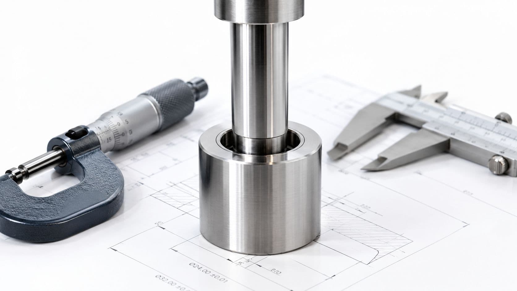
Materials and tolerances aren't separate decisions in a robot build, they're one discussion. A good DFM review asks what the part carries, what it mates with, how it's inspected, and which dimensions drive assembly. If those questions aren't answered early, the prototype turns into a tolerance argument instead of a learning exercise.
Match material behavior to the robot's job
For robot structures, the usual metals include 6061 and 7075 aluminum, 304 and 316 stainless, plus mild and tool steels where wear or stiffness demand it. On the polymer side, ABS, polycarbonate, nylon, PEEK, and POM show up when teams need housings, guides, covers, or light-load mechanisms. The point is not to memorize a materials list, it's to match stiffness, wear, heat response, and machinability to the way the robot moves.
Wall thickness, draft, internal corner radii, and datum strategy matter just as much. Thin walls can distort during machining or printing. Sharp internal corners create stress and tool access problems. Poor datum choices make inspection harder than the build itself.
Practical rule: identify the two or three dimensions that truly control assembly, then loosen the rest where the supplier can still hold function.
That's also where a supplier's DFM feedback should earn its keep. If a callout on a 3D-printed gear seat is written as tightly as a milled aluminum face, the team may be asking the process to do something it doesn't do well. The better move is to reserve tight tolerances for real mating features and use broader standards like ISO 2768 medium or coarse elsewhere when the design allows it.
For a deeper look at how manufacturability reviews catch this kind of mismatch early, this DFM overview is a useful companion reference.
From Prototype to Pilot Production

The handoff from prototype to pilot production is where budgets usually get sharper. Machine time is only part of the bill. Inspection, rework, fixtures, finishing, and integration labor often sit in the shadows until the team starts counting the hours needed to make one robot behave like the last one.
Where the time and money actually go
The path usually runs through concept CAD, DFMA review, digital validation, additive first articles, CNC or sheet metal for functional hardware, integration build, bench testing, pilot run, and bridge production. That sequence is worth respecting because each phase removes a different kind of risk. A print can validate form, a machined part can validate fit and function, and a pilot run can expose whether the assembly is stable enough to repeat.
What gets undercounted is the hidden labor around the parts. Engineers spend time on cable routing, sensor alignment, firmware tweaks, fixture design, and fit correction. Inspectors spend time on CMM checks, 3D scanning, and verification against the drawing. Technicians spend time on finish work, assembly cleanup, and rework when an interface misses by just enough to matter.
The hidden cost line most teams underestimate
Market coverage keeps pointing to high cost and technical complexity as real restraints in robotics prototyping, and it repeatedly flags integration, sensor tuning, and real-world adjustment as part of the problem (Future Market Insights). That matches what happens on the shop floor. The expensive part is often not the first article, it's the work needed to turn a good-looking sample into a prototype that survives messy environments and unpredictable human handling.
If the robot has hardware and software on the same timeline, budget for both. A board spin, a cable change, or a sensor remount can stall the whole build if the prototype was only designed around one discipline. The safer plan is to treat every bridge run as a combined mechanical, electrical, and software event, because that's how the costs show up.
Testing and Validation Practices That Actually Work
A robot prototype isn't proven by motion alone. It's proven when the controls behave in simulation, the mechatronics hold up on the bench, and the system still behaves after the field introduces noise, heat, load changes, and imperfect setup. That's why verification and validation should be treated as a discipline, not a final checkbox.
Layer the tests instead of jumping straight to field trials
Start with software-in-the-loop and hardware-in-the-loop because they catch integration problems before every physical mistake becomes a new print. The technical review cited in the brief makes the point clearly, front-loading digital validation and model-based SIL/HIL testing reduces the number of physical build-test-fix loops and shortens iteration time (UCTM review). That doesn't remove bench testing, it just means the bench starts from a better position.
Bench integration comes next. The robot's mechanics, sensors, wiring, and control stack have to agree with each other under normal operating conditions. After that, environmental checks and field pilots expose the stuff lab conditions hide, like connector looseness, noise sensitivity, and repeatability loss under dynamic load.
The bottlenecks that still break good prototypes
Independent technical and industry sources still call out sim-to-real transfer, safety verification, interpretability, and lack of unified evaluation standards as unresolved bottlenecks for embodied AI and autonomous systems (V&V review PDF). That matters because a prototype can look stable in a controlled environment and still fail in the field when conditions drift. The test plan has to answer both “does it work?” and “can we prove it works repeatedly?”
For dimensional verification on physical parts, this CMM inspection resource is worth keeping handy when a build depends on the geometry staying honest.
A practical pyramid is hard to argue with:
- Prove behavior in simulation first, especially for controls and timing.
- Prove fit and function on the bench second, with the actual hardware stack.
- Prove repeatability in the field third, under the mess the prototype will really face.
- Promote only after the data stays stable, not after the first impressive run.
Compliance and Industry-Specific Requirements
The words “prototype” and “production-grade evidence” don't mean the same thing, and regulated industries care about that gap quickly. The prototype phase is exactly when traceability starts to matter, because once a design has been touched by test data, you need to know what changed, who changed it, and which parts were built from which revision. That applies long before a robot ships.
Medical, automotive, and industrial builds ask for different proof
Medical and surgical robotics tend to lean on ISO 13485 traceability, material certificates, and biocompatibility where skin-contact parts are involved. Automotive robotics and autonomous platforms often move toward IATF 16949 capability and PPAP-style documentation, because process consistency and evidence trail matter as much as the part itself. Industrial and collaborative robotics sit closer to CE/UL machinery safety and functional safety expectations, which changes how guards, interlocks, and documentation are handled.
The practical difference is that a prototype in one sector might be judged as a learning part, while in another sector it already has to live inside a controlled evidence chain. That means revision control, inspection records, and material traceability shouldn't wait for the “real” build. They should start as soon as the first serious prototype leaves CAD.
A team that ignores this early usually pays later in document cleanup, test repetition, or part replacement. A team that plans for it can move faster because the evidence is already organized when the design gets reviewed. The part is still a prototype, but the record around it is already production-minded.
Vendor Selection and Bridge-to-Production Checklist
The best prototype supplier isn't the one that gives the lowest quote on one part. It's the one that can hold the part family together as the design changes from printed sample, to machined function test, to bridge run, to low-volume production. If a vendor can't carry that transition without forcing a redesign, the cheap quote usually becomes expensive later.
What to check before you hand over a robot assembly
Look at the supplier's process breadth first. A useful partner can ship CNC parts, sheet metal brackets, SLA covers, molded pieces, and cast bridge parts without sending you to five different shops. That matters because robotics programs rarely need only one process. They need a stack of parts that line up across the same revision.
Then check the quality and support side. ISO 9001 should be the baseline, with ISO 13485 if the work touches medical programs and IATF 16949 capability if automotive work is in play. You also want DFM feedback, inspection capacity such as CMM and 3D scanning, and enough material breadth to cover engineering plastics, aluminum, and stainless without a scramble. In some programs, a consolidated partner like FIRMFG can fit that role because it combines CNC, 3D printing, sheet metal, molding, casting, and finishing under one roof.
The bridge-to-production test
Ask whether the shop can move a part from SLA sample to vacuum-cast bridge run to rapid-tooled injection molding without a redesign. That's the test. If the answer is yes, the vendor can support the part's learning curve instead of restarting it every time the build matures.
A short checklist is usually enough:
- Process range: one partner can cover metal, plastic, and bridge runs.
- Inspection strength: they can measure what they make, not just machine it.
- Iteration speed: low MOQ and fast turnaround keep the robot program moving.
- Finishing control: in-house surface work reduces handoff drift.
- Engineering support: DFM feedback helps the design fit the process.
- Traceability: the paperwork survives the next review, not just the first shipment.
The point is simple. You're not buying a prototype part, you're buying the next decision in the cycle.
If your robot program is stuck between a promising bench demo and a prototype that can survive real use, FIRMFG can help with CNC machining, 3D printing, sheet metal, molding, casting, and finishing in one manufacturing workflow. Visit FIRMFG to review your parts, compare process options, and move from first article to bridge build with a supplier that understands robotics prototyping.