Flatness vs Parallelism in GD&T: Which Tolerance to Use
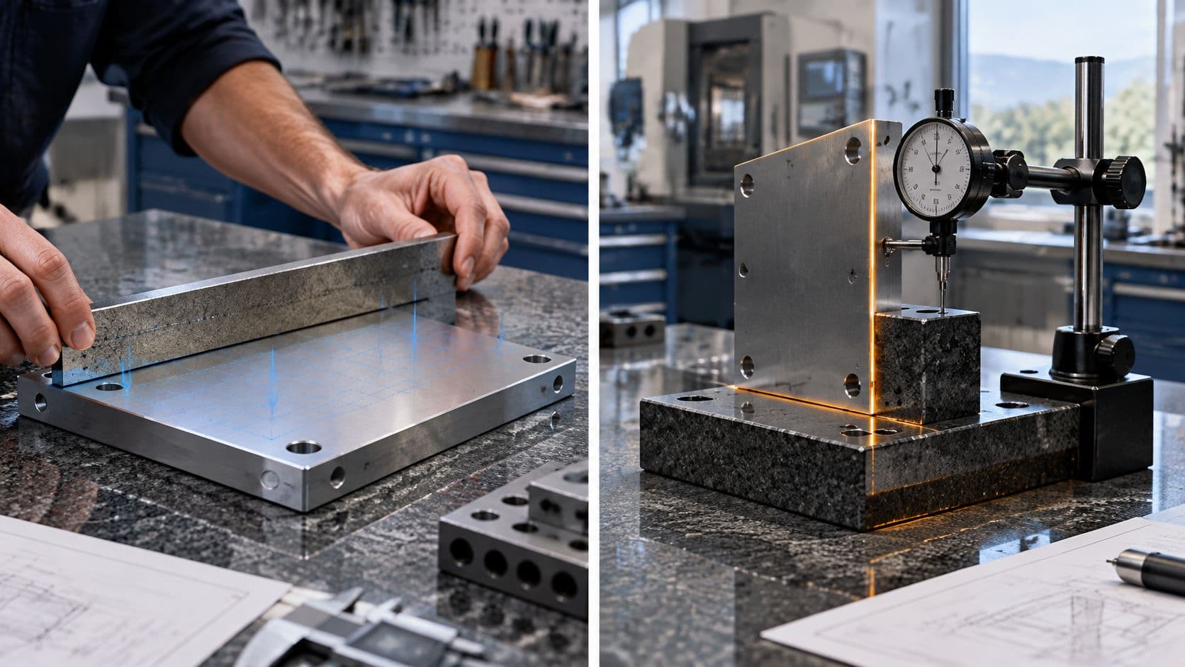
You'll find the same sentence in most guides to flatness vs parallelism: parallelism is flatness with a datum added. It's a tidy summary and it's misleading enough to cause rejections. The two controls share a zone shape, two theoretically exact parallel planes, and not much else. One asks whether a face is even with itself. The other asks whether it sits square to a datum. A part can satisfy the first and fail the second, or the reverse, and no amount of drawing experience lets you reason from one to the other.
The advice gets more expensive when it turns into "call out both and you're covered." Two controls mean two inspection setups, two sampling plans and two chances for a supplier and a customer to disagree about what the numbers mean. They don't overlap the way people assume either. Parallelism constrains orientation. It does not give you independent control of local waviness the way a tight flatness callout does.
What follows is how I work through the choice: which control answers which question, how the feature control frame encodes it, how the datum changes what's measured, and where inspection method decides whether a pass means anything. The frame, the datum simulator and the point count are the three things that determine whether a result is real.
Table of Contents
- Flatness vs Parallelism at a Glance
- What Each Control Measures on a Part
Case one, flat but tilted
Case two, parallel but wavy
Reading Flatness and Parallelism Callouts on the Drawing
Datum Requirements for Flatness and Parallelism
Inspection Methods and Setups That Change the Result- What the plate actually measures
Choosing the Control and Releasing the Drawing- When both controls belong
Flatness vs Parallelism at a Glance
A face can clear a flatness callout and still fail parallelism on the same print. Both controls use two theoretically exact parallel planes set a tolerance value apart. The feature control frame, the datum setup and the inspection sample decide which of those results means anything.
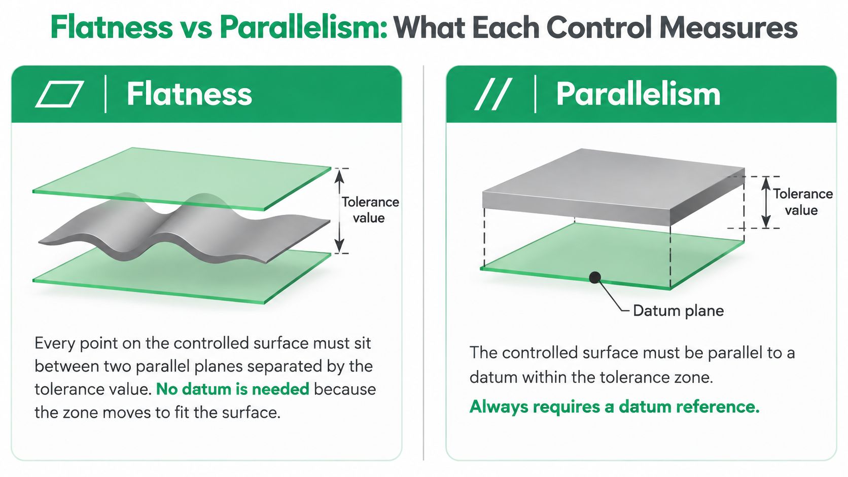
Flatness limits how far a single surface departs from a perfect plane. Parallelism limits how far that surface tilts or shifts relative to a datum. What changes is whether that zone is free to find the surface, or locked in orientation to a datum.
Use the comparison below before you freeze a drawing decision.
| Aspect | Flatness | Parallelism |
|---|---|---|
| Control type | Form control | Orientation control |
| Datum required | No | Yes, one or more datum features |
| How the zone behaves | Translates and rotates freely until it contains the whole surface | Shifts within the datum orientation but cannot tilt away from it |
| What it catches | Waviness, bow, twist, local peaks and valleys | Uniform tilt, misalignment to a base or opposite face |
| Typical features | Sealing faces, sliding surfaces, contact pads | Bearing seats, cover interfaces, guide rails, stacked parts |
| Typical inspection | Independent evaluation of the surface, often by CMM virtual planes | Measurement from a datum simulator set up as the drawing defines |
Flatness asks how even the feature is by itself. Parallelism asks how that feature is oriented to the datum. The zone outline will not tell them apart. I read the datum cell first: empty for flatness, mandatory for parallelism. Leave it blank on an orientation control and there is no legal orientation to measure against.
ASME Y14.5 groups flatness with form controls and parallelism with orientation controls. Sigmetrix's history of ASME Y14.5 traces that codification from USASI Y14.5-1966 through the 1994 revision, a widely taught baseline, to ASME Y14.5-2018. Internationally, ISO 12781-1:2011 defines terminology and concepts for flatness of complete integral features, and ISO 8062-3:2007 lists flatness and parallelism among general geometrical tolerances for castings.
Two mismatches follow. A surface can be flat and still carry a uniform tilt, so parallelism fails while flatness passes. Or it can sit parallel to its datum and still wave enough to fail flatness. Many disputes between a shop and a customer trace back to one of those two cases.
A reported pass only holds if the frame names the control the function needs, the datum simulator matches the drawing, and the sample covers the surface the zone is meant to contain. Change the setup or thin out the points and the same face can flip from accept to reject.
What Each Control Measures on a Part
Flatness is a form control. Every point on the controlled surface must sit between two parallel planes separated by the tolerance value, and no datum is required because the zone translates and rotates until it contains the whole surface. A sealing face where the concern is peaks and valleys across that face is the textbook application, and a 0.05 mm flatness requirement is a normal way to write it, as GD&T Basics sets out in its flatness and parallelism comparison.
Parallelism is an orientation control. A datum feature fixes the zone's orientation, so the zone may shift but can't tilt away from the datum. Put 0.05 mm parallelism to datum A on an opposing rail, and the drawing now controls how that face sits relative to the base rather than how smooth it is in isolation.
Case one, flat but tilted
A 200 mm rail face leaves the mill with a uniform 0.1 mm rise from one end to the other and no measurable waviness along the way. Its flatness is excellent. Two planes close to 0.1 mm apart contain it, and because the zone is free to rotate, a 0.05 mm flatness callout passes without argument.
Send the same face against datum A at 0.05 mm parallelism and it fails, twice over. The tilt is the deviation, and no amount of smoothness rescues it. The face is flat and misoriented at the same time, and only the second control cares.
Case two, parallel but wavy
Reverse the geometry. A cover face measures 0.08 mm of waviness across its width, with its mean plane sitting parallel to datum A. Give it a 0.1 mm parallelism callout and it passes, because the waviness fits inside the oriented zone. Give it a 0.05 mm flatness callout and it fails, because the wave is the deviation.
This is the case people get wrong most often. They assume a parallelism callout with a tight enough value will catch surface texture. It won't do that independently. Orientation and local form are separate properties, and the control that catches texture is flatness. If the feature is a line rather than a face, neither control is right, and straightness is the one to reach for.
The two controls aren't interchangeable, and they aren't redundant either. Each one closes a failure mode the other leaves open.
Reading Flatness and Parallelism Callouts on the Drawing
The feature control frame is where the decision gets locked in, and it's short enough to read cell by cell, left to right.
- Symbol cell: the flatness or parallelism symbol, nothing else.
- Zone cell: the width of the two-plane zone, for example 0.05.
- Datum cell: blank for flatness, at least one letter for parallelism.
A flatness callout is a two-cell frame: the flatness symbol and a value such as 0.05, with no datum reference. Put a datum letter in that frame and you've written a drafting error. The control, as defined in ASME Y14.5, has nothing to reference, and an inspector will either ignore the letter or query the drawing.
A parallelism callout runs three cells or more: symbol, value, then at least one datum, written as 0.05 followed by A in the final cell, where A is the primary datum feature. Every letter in that cell must point to a feature that carries a datum symbol elsewhere on the drawing. If A appears in the frame and nowhere on the part, the callout can't be verified, and the shop is guessing at what you meant.
Here's a pair that works for a machined cover. The gasket face gets a flatness frame at 0.05, because what matters is that the seal sees no local gaps. The bolt face gets a parallelism frame at 0.05 referencing datum A, where A is the base the cover clamps against. Two frames, two different jobs, no overlap.
The drawing has a third obligation that the frame doesn't show. It has to name or imply how the datum is established in inspection, because a datum letter alone doesn't tell anyone whether A is simulated by a plate, a fixture or a CMM plane.
Datum Requirements for Flatness and Parallelism
Parallelism cannot exist without a datum. Flatness never needs one. That asymmetry is the whole rule, and it means datum work comes before you pick a zone value, because the datum defines what the zone is measured against.
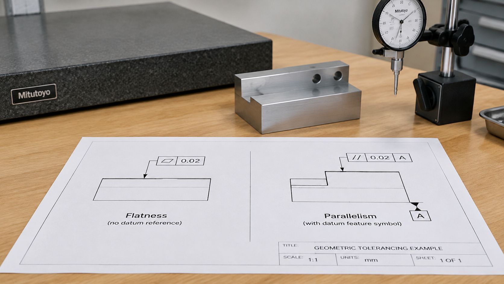
Five steps cover it.
- Find the seat. Identify the mating part or base that defines how the component sits in the assembly. Not the face that's easiest to clamp, and not the face the machinist would rather indicate.
- Name it as datum A. The primary datum is normally the first surface that contacts the mating part and constrains the most degrees of freedom.
- Confirm the controlled face. Make sure the surface carrying the parallelism frame is the one that must stay oriented to that seat. If you're also controlling location, that's a different tool entirely, since true position handles location while orientation tolerances leave it free.
- Choose the simulator. The drawing should establish how the datum is realized: a surface plate, a mandrel, a dedicated fixture, or a plane constructed in CMM software. Pick the one that matches assembly contact.
- Write the frame. Zone value first, datum reference last. A machined cover bolted against a base becomes 0.05 parallelism to A, where A is that base face.
The simulator is where drawings fail. A burr or a chip under datum A lifts one corner, tilts the reference the zone is oriented to, and the resulting error belongs to the setup rather than the part. I would stone the plate and wipe the datum before blaming a machine.
Before the indicator moves: clean the datum face and check its own form. A bowed datum shifts the simulated reference plane, so the orientation you measure includes the datum's error.
That last point deserves its own sentence. If datum A carries a 0.03 mm bow, the reference plane it establishes moves with it, and a tight parallelism callout on the opposite face is now judged against a reference that isn't flat. Control the datum's flatness when the datum is doing real work, or the whole stack is built on sand.
Engineering Technology's guide to form tolerances makes the practical split cleanly: specify flatness for sealing faces, sliding surfaces and contact stability where absolute orientation isn't the concern, and specify parallelism when a face must stay aligned with a datum, as with a bearing seat, cover interface, guide rail or stacked component. The same source warns against applying both by default, because parallelism doesn't necessarily deliver the independent control of local waviness that a tight flatness specification provides.
One more discipline point. The datum has to be chosen for assembly function, not for convenience at the inspection bench. A datum that's easy to clamp but irrelevant to how the part bolts up produces a report that passes and a product that leaks.
Inspection Methods and Setups That Change the Result
| Method | Flatness | Parallelism | Best for |
|---|---|---|---|
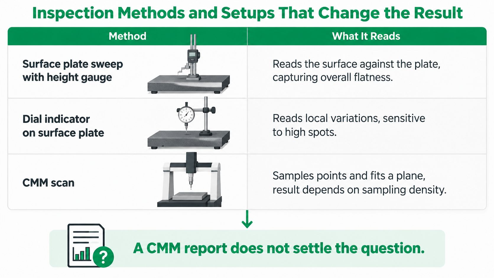
| Surface plate with height gauge or dial indicator | Sweep the surface and read maximum deviation; the plate can bias the result toward a parallelism-style reading | Set the datum on the plate or in a fixture, then read the controlled surface against it | Quick checks on small parts and shop-floor verification |
| CMM with virtual planes | Independent best-fit or minimum-zone evaluation from scanned points | Datum simulation defined on the drawing, then orientation measured from the datum | Production parts, disputes and tight tolerances |
| Dial indicator on a mandrel or fixture | Limited to features that can be referenced to the fixture | Common for bores and datum-referenced faces | Repeat checks on batches with a fixed datum |
| Optical flat or interferometer | Fine flatness on reference surfaces | Rarely used for parallelism on production parts | Gage blocks, lapped plates and reference surfaces |
What the plate actually measures
A surface plate sweep with a height gauge is the setup most guides show, and it has a built-in bias. The indicator reads the controlled surface against the plate. That is a measurement relative to a reference, so with a datum in play it behaves like a parallelism reading rather than a datum-free flatness value, a limitation Fractory's inspection notes call out directly.
True flatness needs the surface evaluated independently of its orientation. In practice that means fitting planes to scanned points, not sweeping along a plate. CMM software can construct virtual planes and evaluate them with a least-squares fit or a minimum-zone rule. The result still depends on datum simulation, point distribution, fixturing, temperature, probe strategy and the evaluation algorithm the programmer selected.
That makes "CMM inspected" a claim about equipment, not about control.
Sampling and uncertainty decide the verdict
NIST's test artifact inspection sheet recommends a minimum of 10 measurement points for flatness, and at least 5 points for parallelism or perpendicularity when enough points are used to establish the relevant lines or planes. Those are planning minimums, not acceptance rules. Large surfaces, thin plates, warped castings and parts with visible cutter marks need denser, distributed sampling or a full scan.
Sparse point sets are how warped parts pass. More measured points generally represent the surface better, move the estimated flatness toward a convergent value and reduce uncertainty, which means a four-point check on a bowed casting can report flatness the part doesn't have.
Uncertainty works the same way. NIST identifies reference-surface geometry, alignment and motion errors as major sources in precision surface measurement, and computes combined standard uncertainty as the square root of the summed squares of the individual components. Set a 0.02 mm combined uncertainty against a 0.05 mm tolerance and the measurement system has consumed 40 percent of the allowable band before the process gets a vote.
Practical rule: when uncertainty is a large share of the tolerance, improve the setup before you ask for rework. A part rejected by a marginal measurement is a rework order nobody needed.
On reference surfaces the scale changes again. A 2024 comparative study published in the Indian Journal of Engineering & Materials Sciences reported optical-flat flatness of 120.50 ± 30 nm using laser interferometry and 118 ± 32 nm using image processing. That's the regime where an optical flat belongs, and it's not the regime of a milled cover.
Our own inspection route at FIRMFG uses CMM and calibrated digital calipers, with results documented against CAD nominal values and specified tolerances. The documentation questions below apply to that output exactly as they apply to any other supplier's.
Ask for five things on any tight callout: the datum setup, the probe strategy, the point distribution, the temperature control and the measurement uncertainty. Pass or fail alone tells you what happened, not whether it means anything.
Choosing the Control and Releasing the Drawing
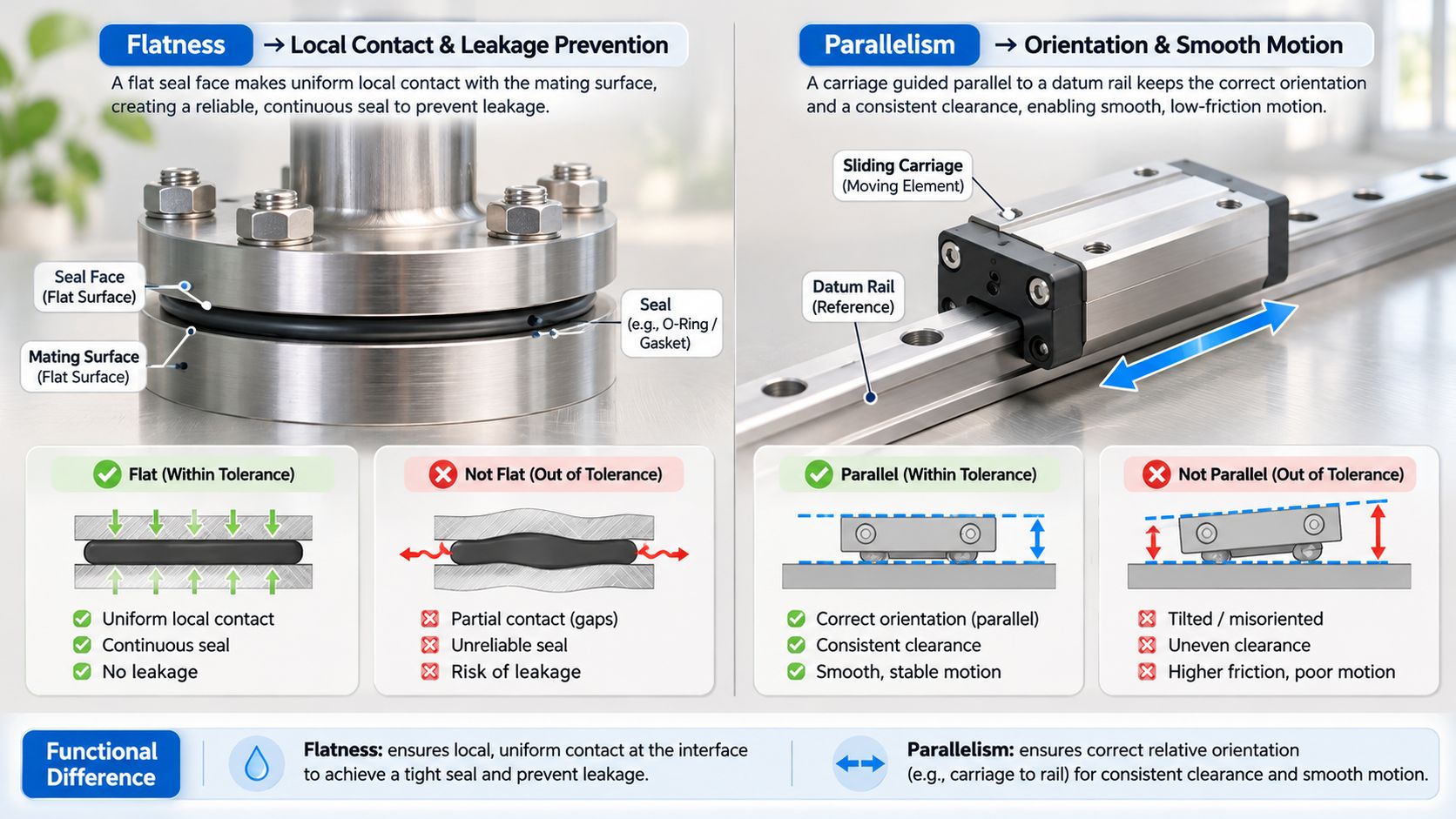
Start from what the face does in the assembly, not from which symbol looks stricter. Local contact, sealing or sliding smoothness across a face points to flatness. Orientation to a datum that drives fit, alignment or load path points to parallelism.
| Application | Specify | Why | Check alongside it |
|---|---|---|---|
| Gasket or O-ring sealing face | Flatness | Local gaps leak even when the face is level overall | Parallelism only if the mating face must stay square to a datum |
| Linear guide rail mounting face | Parallelism to datum | The rail must track the base reference | Flatness on the mounting pad if it carries load |
| Bearing seat bore relative to housing face | Parallelism to datum | Orientation controls shaft alignment | Check the datum that defines the seat |
| Plate sliding over another plate | Flatness | Waviness causes binding and uneven wear | Parallelism alone can pass a bowed plate |
| Stacked components sharing a base | Parallelism to primary datum | Tilt accumulates across the stack | Flatness on each contact face if contact is local |
When both controls belong
Sometimes the function needs two callouts. A pressure-sealed plate that seats on a referenced base has to be flat enough to hold the seal and parallel enough to load the base evenly. That's a legitimate pair, and each frame should carry a zone value set from its own failure mode rather than copied from the other.
Defaulting to both on every face is a different matter. Every extra callout adds inspection time, adds a sampling decision and adds an argument waiting to happen when the two results disagree at the limit. Specify what the function needs and stop.
Cost follows the same logic. Tighter flatness usually pushes the process from milling into grinding or lapping, and the price steps up along the range of CNC machining tolerances rather than sliding smoothly. Long parallelism features can demand datum-referenced fixturing that a flatness-only part would machine in a standard vise.
The release checklist
- Confirm the assembly function. What does this face touch, seal, slide against or align?
- Choose one control, or two with separate reasons. Never add a second callout "for safety."
- Name the datum and its simulator whenever parallelism appears in the frame.
- Set the zone value from function, not from a house default or the last similar job.
- State the inspection method and point distribution so the supplier measures the property you intended.
- Request the datum setup, sampling plan and measurement uncertainty with the first article report.
Step six carries the most weight on parts that sit near their limit. A manufacturer that documents CMM results against the drawing can also review the datum scheme during design-for-manufacture feedback, which is where a bad datum choice is cheapest to fix. FIRMFG runs that review before cutting metal, and a datum that looked fine on screen sometimes doesn't survive contact with a fixture.
A tolerance is only as good as the datum and the inspection that verify it. The number on the drawing is the smallest part of the decision.
Get that order right and the symbol choice almost makes itself. Get it wrong, and a perfectly machined part fails a report it never should have seen.
Flatness and parallelism callouts only pay off when the shop can measure them the way the drawing intends, against a real datum simulator with a documented sampling plan. FIRMFG machines prototypes and low-volume parts to drawing tolerances and verifies them with CMM and calibrated digital calipers, with results recorded against CAD nominal values and specified tolerances. If you're finalizing a drawing with either control, send it over for DFM feedback before the first chip and we'll flag a datum that's hard to simulate or a zone value that pushes the part into grinding. Visit FIRMFG for a quote, with no minimum order quantity and quotes issued in hours.