True Position Symbol in GD&T: A Practical Engineer Guide

The print has reached inspection, the machined plate is on the bench, and someone points to a crosshair inside a rectangular frame. The hole diameter looks acceptable, but the assembly question is still open: will the mating pin fit, and what evidence does the drawing require before you release the part?
Table of Contents
What the True Position Symbol Actually Controls- Separate the target from the permitted variation
Reading the Feature Control Frame Cell by Cell- Compartment by Compartment Breakdown of a Position Callout
How Datum References Give Position Its Meaning- Distinguish the datum from the datum feature
MMC, LMC, RFS, and the Bonus Tolerance Calculation- Work the allowance from the measured size
When Position Beats Coordinate Plus or Minus Tolerances- Compare the requirement before choosing the notation
Inspection Methods That Verify True Position- Match the evidence to the callout
Reading Checklist for the True Position Symbol on a Drawing- A repeatable print-reading procedure
A Shop-Floor Moment with the True Position Symbol
An inspector brings you a drawing with a position callout beside a hole-size dimension. The frame contains the true position symbol, a diameter-prefixed tolerance, a material-condition modifier, and datum letters. The machinist wants to know whether to adjust the setup. Quality wants an acceptance decision.
Neither question can be answered by measuring the hole diameter alone. You need to connect the callout to the feature it controls, the references used to locate that feature, and the inspection method that will demonstrate compliance.

Start with the inspection question
Treat this as a hypothetical mounting-plate inspection, not a documented production case. The inspector has measured a hole, but the report alignment was built from whichever edges were easiest to reach. Before discussing acceptance, you ask whether those edges correspond to the drawing's datum references.
That question changes the conversation. A measurement can be repeatable without answering the requirement on the print.
- Design asks about function. Does the controlled feature occupy a location compatible with the mating component?
- Manufacturing asks about correction. Should the team investigate workholding, the machining origin, or the feature-making operation?
- Inspection asks about evidence. Does the measured result represent the specified feature in the specified reference frame?
Bench-side rule: Agree on what the drawing requires before debating what the measurement means.
Keep the drawing beside the inspection report. Mark the controlled feature, trace its locating dimensions, and identify the datum features on the physical part. That gives everyone a common starting point without assuming that a green software result is sufficient evidence.
What the True Position Symbol Actually Controls
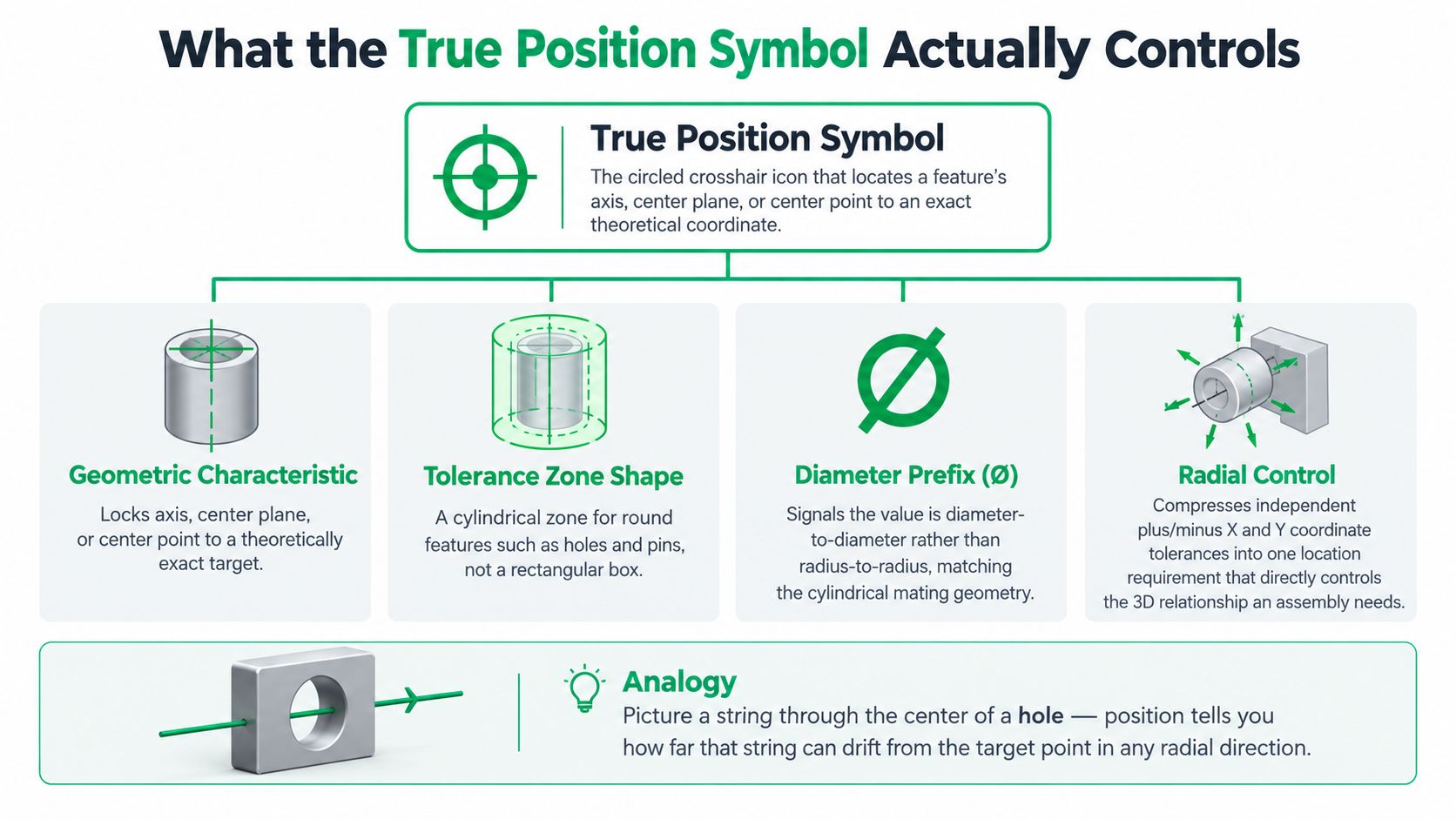
The true position symbol, ⌖, identifies a location control. It controls a feature's axis, center point, or median plane relative to a theoretically exact position established by basic dimensions and a datum reference frame, as described in NIST guidance on datum selection and feature-axis control.
For a cylindrical feature, the diameter prefix describes a cylindrical tolerance zone, not a rectangular box. A position requirement of ⌀0.20 mm means the derived feature axis must remain inside a cylinder of that diameter centered on the nominal axis, under the NIST guidance cited above.
Separate the target from the permitted variation
The basic dimensions establish the target. The position tolerance establishes the permitted departure from it. Don't treat a basic locating dimension as another independently toleranced coordinate.
A useful mental model is a string running through the center of a hole. The nominal axis is where that string should lie; the tolerance zone is the surrounding boundary within which the derived axis must remain. The string analogy helps with visualization, but inspection must evaluate the feature representation required by the drawing, not a conveniently selected point.
- Size answers how large. A diameter measurement addresses the hole's size requirement.
- Position answers where. The location evaluation addresses the controlled feature relative to its theoretical target.
- Zone shape answers how variation is bounded. The diameter prefix tells you to think about a cylindrical boundary rather than independent coordinate limits.
The practical consequence is important: a hole can have acceptable size while its axis occupies an unacceptable location. Conversely, an acceptable position result doesn't excuse an out-of-size hole.
For a comparison with another geometric control, consult this guide to geometric tolerance straightness. When reviewing a print, keep the question precise: are you evaluating where the feature belongs, or a different aspect of its geometry?
Reading the Feature Control Frame Cell by Cell
Read the feature control frame from left to right, but don't assume every mark occupies a separate compartment. In a conventional position frame, the tolerance value and its associated material-condition modifier appear together. Datum references follow in their own compartments.
A useful conceptual template is position symbol | zone and tolerance with optional modifier | primary datum | secondary datum | tertiary datum. This is a reading aid, not a substitute for the drawing's governing standard.
Compartment by Compartment Breakdown of a Position Callout
| Compartment Position | Typical Content | What It Tells You |
|---|---|---|
| Leftmost compartment | ⌖ | The geometric characteristic is position |
| Tolerance compartment | Diameter prefix and tolerance value | The zone shape and permitted variation |
| Within the tolerance compartment | Ⓜ or Ⓛ, when specified | The material condition associated with the tolerance |
| Following datum compartment | A datum letter | The primary reference |
| Subsequent datum compartments | Additional datum letters | The remaining references in their specified order |
Don't look for a circled letter meaning “RFS” on a typical contemporary frame. Regardless of Feature Size, abbreviated RFS, is ordinarily the default for the feature tolerance when no material-condition modifier is shown. Confirm the drawing standard before interpreting unfamiliar or legacy notation.
A modifier attached to the tolerance and a modifier attached to a datum reference are not interchangeable. Their placement matters. If you encounter a modified datum reference, resolve its effect on datum establishment separately rather than adding it automatically to the feature's tolerance allowance.
Read the frame together with its attachment and the associated dimensions. A correctly interpreted frame applied to the wrong feature still produces the wrong inspection.
The same discipline helps distinguish position from other controls. This geometric tolerancing runout guide provides a useful comparison when a print contains rotational requirements as well as location requirements.
How Datum References Give Position Its Meaning
Suppose an inspector aligns a mounting plate to its outside edges while the assembly locates it through a mounting face and locating features. The inspector may obtain consistent coordinates, yet those coordinates can describe a different relationship from the one the designer intended.
Datum references establish the context for location. The primary, secondary, and tertiary sequence progressively constrains the part and establishes the reference frame. As noted in the NIST guidance above, datum selection should reflect the part's functional interfaces.
Distinguish the datum from the datum feature
The physical surface or feature identified on the part is the datum feature. The datum itself is the theoretically exact reference established from that feature through the applicable datum-simulation process. Keeping those terms separate helps engineers avoid treating an imperfect machined surface as a perfect mathematical plane.
For a familiar analogy, consider a circuit board seated in a fixture. The support, locating arrangement, and stop determine how the board sits before anyone checks a connector location. Your part's datum structure serves a comparable locating purpose, although its actual constraints depend on the specified geometry.
- Primary reference: Establish the first locating relationship before using the remaining references.
- Secondary reference: Add the next constraint without replacing the primary relationship.
- Tertiary reference: Complete the required alignment in the order shown on the drawing.
Don't assume every datum arrangement follows an identical planar locating scheme. A bore, a datum pattern, or a targeted surface requires a setup appropriate to that definition.
A convenient inspection origin isn't automatically a valid datum reference frame.
Before collecting feature data, inspect the locating contacts. Remove chips, check for burrs, and confirm that clamping doesn't undermine the intended seating. Then document the alignment so another inspector can reproduce the required reference relationship, not merely the fixture's appearance.
MMC, LMC, RFS, and the Bonus Tolerance Calculation
Maximum Material Condition, or MMC, means the permitted feature size containing the most material. For an internal hole, that's the smallest permitted hole. For an external pin, it's the largest permitted pin. Least Material Condition, or LMC, describes the opposite size condition.
An MMC position requirement can allow additional positional variation as the feature departs from MMC. That additional allowance is bonus tolerance, and it reflects available assembly clearance rather than an arbitrary relaxation of the drawing.
Work the allowance from the measured size
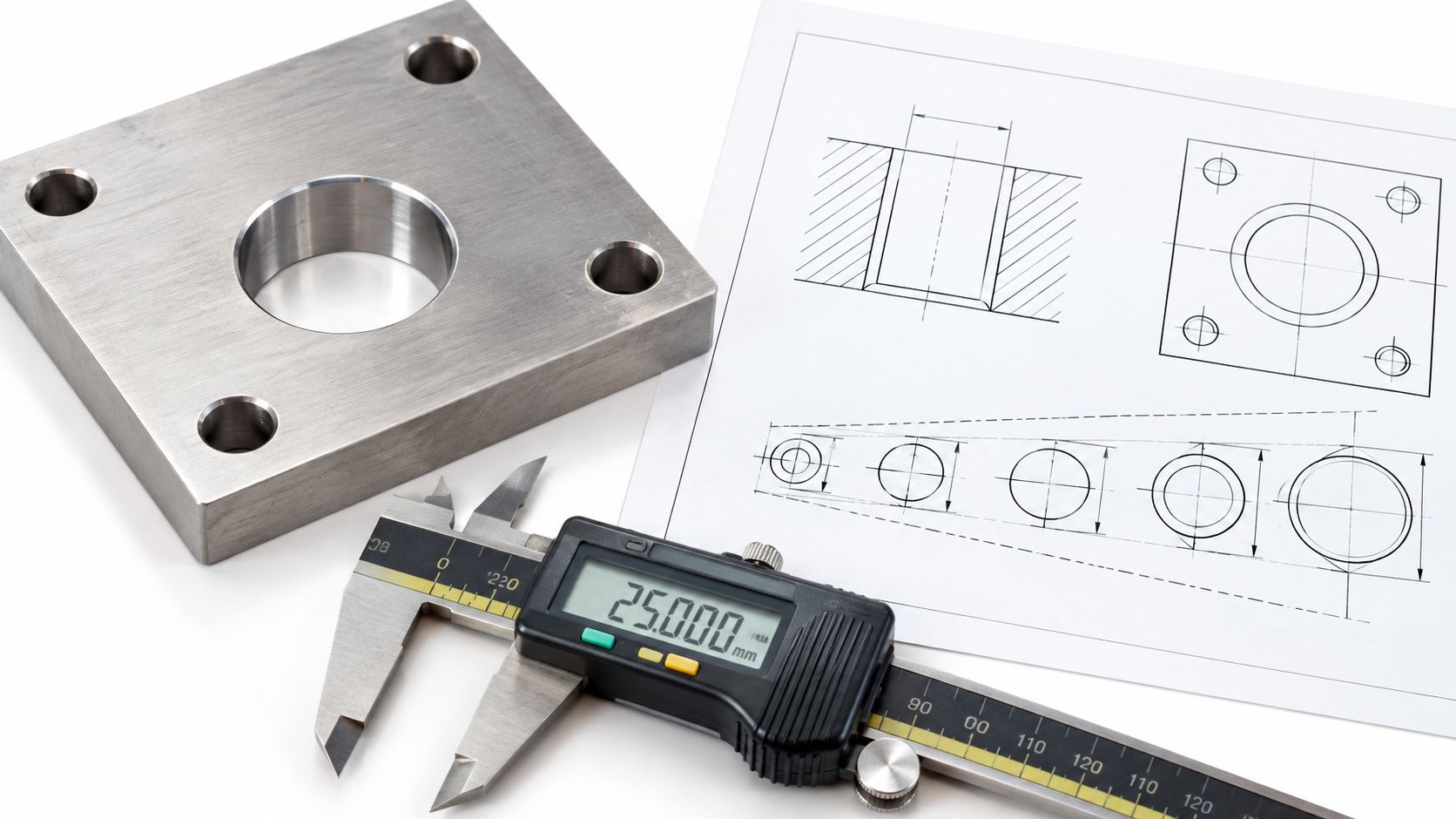
For a hole specified as ⌀10.00 +0.10/0 mm with position ⌀0.20(M), the positional allowance is 0.20 mm at the MMC hole size of 10.00 mm; at a measured size of 10.06 mm, the hole gains 0.06 mm bonus, giving a total allowance of ⌀0.26 mm, provided the virtual-condition boundary remains satisfied, as described in NIST documentation and supporting GD&T teaching material on tolerance boundaries and MMC bonus.
The calculation follows a simple relationship:
Total permitted position tolerance = stated position tolerance + eligible departure from MMC
The manufacturing consequence is useful. A larger acceptable hole can accommodate additional location variation while preserving the specified worst-case assembly boundary. The inspector must still verify the size requirement independently.
- At MMC: Evaluate against the stated position allowance.
- Away from MMC: Determine the eligible size departure and apply the associated bonus.
- At RFS: Don't add a material-based bonus; evaluate against the stated position allowance regardless of feature size.
- With LMC specified: Evaluate departure from the least-material condition using the applicable rules, rather than reusing the MMC calculation direction.
Keep the boundary in the decision
The virtual condition expresses the combined worst-case boundary associated with size and geometric tolerance. Bonus tolerance doesn't authorize an inspector to ignore that boundary or accept a hole outside its size limits.
A clean report separates measured size, measured position, stated tolerance, bonus, and total allowance. That prevents a reviewer from mistaking the enlarged acceptance limit for the actual measured positional error.
When Position Beats Coordinate Plus or Minus Tolerances
Choose the control by asking what the mating geometry requires. For a round hole engaging a round pin, position often expresses the location requirement more directly than independent horizontal and vertical limits.
The distinction is geometric, not stylistic. Independent coordinate tolerances permit variation separately along each coordinate direction. Position combines those directions into a radial location requirement, consistent with the cylindrical-zone principle described earlier.
Compare the requirement before choosing the notation
| Approach | Best question to ask | Inspection consideration |
|---|---|---|
| Coordinate plus or minus tolerances | Are separate coordinate limits sufficient for function? | Check the specified coordinates without substituting a position acceptance rule |
| Position | Does the axis or center location need a datum-related geometric boundary? | Evaluate the controlled feature using the specified zone and material condition |
| Profile of a surface | Does the requirement concern the surface itself as well as its location? | Plan a surface evaluation rather than treating it as a hole-center check |
Don't convert coordinate limits into a position tolerance by copying the same displayed value. Different zone shapes permit different sets of feature locations. The designer needs to select the replacement requirement from assembly needs, not visual similarity between callouts.
Profile can be appropriate when surface shape and placement are central to function. It isn't automatically too strict or more expensive to inspect. Those consequences depend on the requirement, feature accessibility, and chosen measurement method.
Design review prompt: Specify the relationship the assembly needs, not the notation your team uses most often.
Position also isn't unsuitable for sheet metal or non-rigid parts. Those applications demand careful attention to restraint, datum establishment, and the condition in which acceptance is evaluated.
For a simple, noncritical feature, coordinate tolerances may adequately express the design intent. For a surface contour, profile may be clearer. Use position when its controlled feature and boundary match the functional question, rather than applying it to every feature for drawing consistency.
Inspection Methods That Verify True Position
The inspector seats the part against the specified references before checking the hole. From that point, the choice is between demonstrating a boundary condition and producing dimensional evidence. Those are related objectives, but they don't always require the same equipment.
A functional gauge can check an applicable assembly boundary through engagement with fixed locating and checking elements. It doesn't automatically provide the measured positional error. Its design, datum simulation, and applicability must match the requirement.
Match the evidence to the callout
- Functional gauging: Use an appropriately designed gauge when boundary acceptance is the required evidence. Maintain separate verification of requirements the gauge doesn't establish.
- Optical inspection: Consider an optical comparator or vision system for accessible feature locations, but don't assume a visible opening proves the axis relationship through the feature's depth.
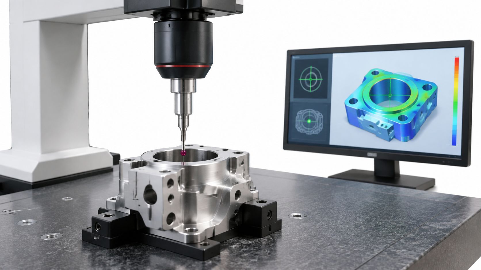
- CMM inspection: Establish the datum alignment, sample the controlled feature appropriately, and evaluate the resulting geometry against the specified requirement.
For a bore, probing only near the opening can overlook behavior deeper inside the feature. Plan access and sampling to represent the controlled geometry. Don't accept a fitted cylinder merely because the software produced one; confirm that its association and evaluation settings suit the drawing.
Review the report configuration
A diametral position result and a radial offset are different reporting conventions. Confirm which the software displays before comparing the result with a diameter-prefixed tolerance.
Also check the datum order, feature identifier, material-condition setting, and reported allowance. A green status field is meaningful only when those inputs are correct. This overview of CMM inspection services offers additional context for planning dimensional verification.
Reading Checklist for the True Position Symbol on a Drawing
Use the callout as an inspection instruction, not just a tolerance value. A reviewer should be able to follow the drawing, the setup, and the report without guessing how the inspector arrived at the decision.
A repeatable print-reading procedure
- Identify the controlled feature. Trace the frame's attachment and confirm whether the evaluation concerns an axis, median plane, or other specified feature representation.
- Read the zone requirement. Check the tolerance value, units, and diameter prefix where present.
- Resolve the material condition. Determine whether the feature tolerance is modified, then establish any eligible allowance from valid size evidence.
- Locate the theoretical target. Find the associated basic dimensions rather than using measured coordinates as the nominal location.
- Follow the datum sequence. Map each reference to its physical datum feature and the planned simulation.
- Select suitable evidence. Decide whether boundary verification, dimensional reporting, or both are needed.
- Audit the acceptance result. Confirm that alignment, feature evaluation, reporting convention, and allowance agree with the print.
Finish with a release exercise
Return to the mounting plate from the opening scenario. Its frame shows position, a diameter-prefixed tolerance, an MMC modifier, and datum references in the specified sequence. Use the previously worked bonus calculation without treating that allowance as proof that the feature passes.
The inspector verifies acceptable size, establishes the required datum frame, and evaluates the controlled axis. The reviewer then compares the measured position with the applicable allowance and checks the relevant boundary requirement. If the report doesn't contain sufficient evidence, the correct action is to complete the evaluation, not infer acceptance.
Common traps include evaluating the wrong hole, using a convenient alignment, reporting radial offset as diametral position, and leaving bonus tolerance hidden in software settings. Make those checks explicit in the inspection review.
A defensible decision connects the print to the physical setup and the reported result. Keep that connection visible, and the true position symbol becomes a practical manufacturing requirement rather than an ambiguous mark.
FIRMFG offers CNC rapid prototyping and precision machining for metal and plastic parts, with DFM feedback and inspection support. Visit FIRMFG with your drawing and part model to discuss datum selection, position requirements, and the inspection evidence needed for your prototype or low-volume build.