Injection Molding Prototype Guide for Engineers in 2026
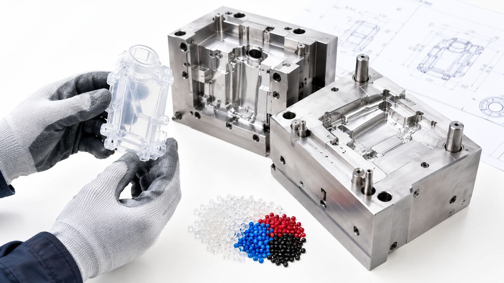
The CAD review is over, the enclosure looks clean, and the team is ready to test the next build. Then someone asks the question that changes the schedule and budget: does this part need to be molded, or can CNC machining, 3D printing, or vacuum casting answer the same engineering question first?
The right choice depends on what you need to learn. An injection molding prototype is valuable when the test depends on production-like thermoplastic behavior, but it isn't automatically the best next step after CAD. Treat validation as a sequence: use the quickest, least expensive process that can answer the current question, then move to a mold when the remaining uncertainty justifies it.
Table of Contents
How the Injection Molding Process Actually Works- Heat, inject, cool, eject
Rapid Tooling and Low-Volume Mold Options Compared
Choosing the Right Resin for Prototype Molding- Shortlist by performance need
Realistic Tolerances and Dimensional Control for Prototypes- Call out what controls function
Lead Time and Cost Drivers You Can Actually Forecast- Compare the quote on equal terms
Design for Manufacturing Tips Before You Cut the Tool
What a Prototype Can and Cannot Tell You About Production- Carry evidence into the next tool
When an Injection Molding Prototype Is the Right Next Step
Consider a product team refining a snap-fit enclosure. The first question is whether the two halves align and whether the connectors clear the surrounding geometry. A CNC or 3D-printed part can answer that without a mold. If the next question is whether a production-grade resin will flex without cracking, maintain a seal, or survive repeated assembly, a molded sample becomes much more informative.
Start by stating the decision the prototype must support. “We need to test the part” is too broad. Ask whether the team needs to check dimensions, fit, appearance, material performance, or manufacturability. Different processes reveal different things, and a part can look convincing while still behaving unlike the final production component.
Match the process to the question
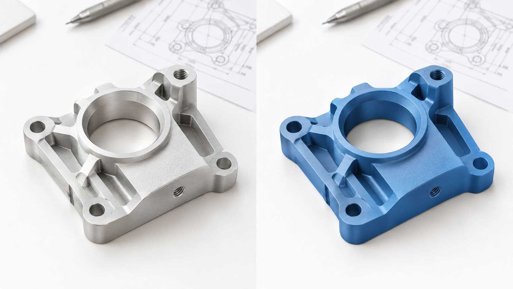
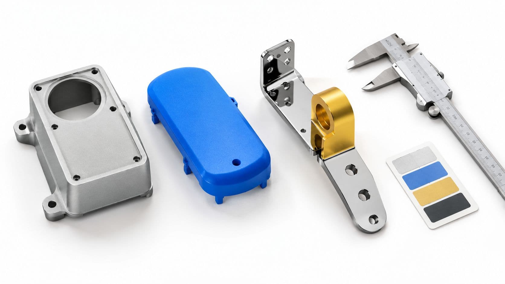
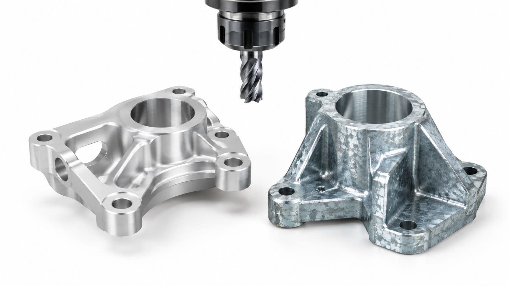
- CNC machining is useful for checking geometry, interfaces, and dimensions in a selected material. It can be a strong choice when the part needs accurate features or a quick test of a rigid component.
- 3D printing supports fast design iterations and complex shapes. It can reveal interference and ergonomic issues, but printed material and layer construction may not reproduce molded-part strength or surface behavior.
- Vacuum casting can produce small batches for fit, assembly, appearance, and early functional reviews. It uses polyurethane casting resins, so it shouldn't be treated as proof of how a production thermoplastic will perform.
- Prototype injection molding is the better fit when the team needs to evaluate the intended thermoplastic's flow, shrinkage, flex, sealing, heat response, or repeated-use behavior.
Mold-flow analysis can help teams examine gate placement, filling risk, weld lines, warpage, packing, and cycle-time effects before cutting a tool. One reported comparison found simulated and actual results correlated within ±10% (research on mold-flow simulation and design validation). Simulation informs decisions, but it doesn't replace a physical test when the unknown is material behavior or real-part performance.
Decision rule: Mold only when molding answers a question that the available alternatives can't answer well enough.
Before requesting a quote, write down the expected part quantity, required material fidelity, mechanical loading, cosmetic needs, and intended production volume. If those needs point to molded behavior, prototype tooling may be the practical way to reduce uncertainty. If they point only to shape and interface checks, start with a less involved process.
How the Injection Molding Process Actually Works
A useful mental model is a coffee machine. Plastic pellets are the beans, the heated barrel is the boiler, and the machine's screw or plunger moves the softened material. The mold is the cup, while its cooling channels help set the part before ejection. The comparison isn't exact, but it helps explain why molding is a controlled sequence rather than just pressing plastic into a shape.
Heat, inject, cool, eject
First, the machine heats the resin until it can flow. Melt temperature matters because material that isn't sufficiently softened may not fill the cavity, while excessive heat can damage the resin or affect appearance. The appropriate processing window depends on the material and part.
Next, the screw or plunger pushes the melt through the nozzle and gate into the cavity. Injection velocity affects how quickly the cavity fills. If the material can't reach a thin or distant feature, the result may be a short shot. If the fill behavior or tool closure isn't controlled, flash can form at the parting line.
Once the cavity fills, the machine applies holding pressure to push more material into the cavity as the part begins to shrink. This packing stage affects how completely the part forms and how consistently its dimensions settle. Too little or poorly controlled packing can contribute to sink or dimensional variation; too much can create other process problems.
Then the part cools in the mold. Cooling time and channel layout influence how evenly the resin solidifies, which affects cycle time, shrinkage, warpage, and the risk of distortion during ejection. Finally, ejector pins or another release mechanism push the solid part out. If the part sticks, the tool or part design may need adjustment.
A molded part is the outcome of both geometry and processing. The tool, resin, temperature settings, fill behavior, packing, cooling, and ejection all shape the result. When a prototype misses a dimension or has a cosmetic defect, don't assume the CAD model is the only possible cause. The process window and tool design may need attention too.
Rapid Tooling and Low-Volume Mold Options Compared
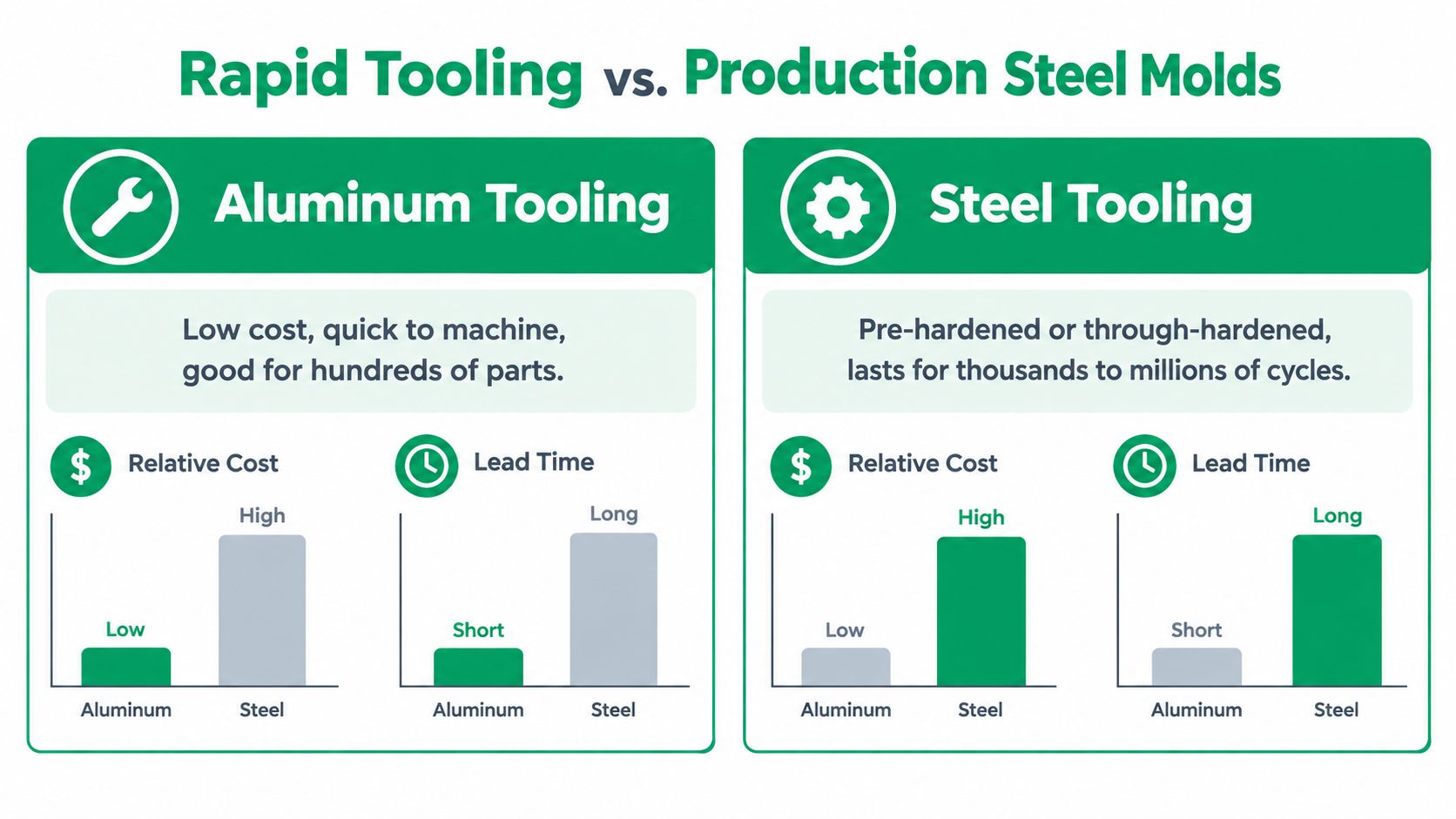
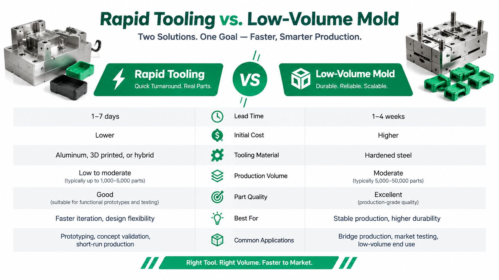
A prototype mold can mean several different things. A machined aluminum tool, a steel mold, and an additively manufactured insert have different limits and trade-offs. Choose based on the validation task and expected use, not on the label “rapid tooling.”
Aluminum tooling is often considered for short runs and design iteration. Steel tooling is more durable, but its material and machining effort may be difficult to justify when the design is still changing. Polymer or additively manufactured inserts can support early trials, though their thermal behavior and durability need careful review. Hybrid tools combine materials or methods to balance those requirements.
| Prototype Tooling Classes at a Glance | Typical Lead Time | Usable Shot Count | Best Validation Goal |
|---|---|---|---|
| Additively manufactured or polymer insert | Tooling may be produced quickly; timing depends on the method and design | Varies with insert material, resin, pressure, and thermal management | Early design iterations and short trials |
| Aluminum tooling | Depends on complexity, machining, and finish | Varies by tool design and operating conditions | Functional and dimensional checks in a short run |
| Pre-hardened steel tooling | Depends on machining and tool complexity | Higher durability than many rapid inserts; confirm with the toolmaker | Broader validation where tool stability matters |
| Through-hardened production steel | Usually requires a production-tool schedule | Intended for sustained production use | Production process development and continued manufacture |
A 2025 micro-injection-molding study compared polymer tooling with aluminum tooling using a micro-tensile-bar geometry. Under the reported test conditions, tensile properties were within 6.4% of the metal-tool baseline, while energy use was reduced by as much as 17.6% per molding cycle (comparative micro-injection-molding study). Those results show that polymer tooling can be useful in a controlled application. They don't establish universal equivalence with production steel.
Thermal conductivity is a key limitation. A polymeric insert may remove heat less effectively, extending cooling and increasing temperature variation or deformation risk. Demanding materials such as acetal and polycarbonate can make tool durability and heat removal especially important. Research on additively manufactured inserts describes satisfactory output for those materials as commonly limited to approximately 10–100 parts (research on additively manufactured injection inserts).
For an overview of options and considerations, see FIRMFG's guide to injection molding with 3D-printed molds. Ask the toolmaker to tie the recommendation to resin, part geometry, expected shot count, and the properties you need to validate.
Choosing the Right Resin for Prototype Molding
Resin choice affects whether a molded prototype tells you anything useful about the production part. A substitute may fill the mold and look right, yet produce misleading results if its stiffness, shrinkage, moisture response, or heat behavior differs from the intended grade.
Start with the function. List the part's mechanical loads, temperature exposure, chemical contact, appearance requirements, and any applicable regulatory or quality framework. For medical or automotive work, confirm what material and documentation the program requires rather than assuming that a broadly similar resin will be acceptable.
Shortlist by performance need
ABS is a common candidate for general-purpose housings and cosmetic evaluation. A particular grade's flow and shrinkage still matter, so don't treat all ABS resins as interchangeable.
Polycarbonate may suit parts that need impact performance or clarity. Its processing conditions and tool-temperature demands should be confirmed with the molding supplier, especially if the prototype uses a rapid insert.
Polypropylene is worth considering for flexible features such as living hinges or for applications involving chemical exposure. Its flexibility can make it useful for testing part behavior, but the production grade should be represented as closely as practical.
Nylon and glass-filled engineering grades can be appropriate when wear resistance, heat performance, or stiffness matters. Nylon's moisture sensitivity can influence dimensions and mechanical behavior, while reinforcement changes flow and the way a part responds to loading.
Don't select a resin by family name alone. A supplier's datasheet and processing recommendations can help narrow the choices, but the specific grade should match the production intent. If the final component uses a reinforced or specially modified grade, testing an unfilled substitute may conceal problems.
Practical rule: Choose the closest feasible production resin before you choose the prototype tool.
That sequence helps the toolmaker assess the processing window and cooling needs against the material the team wants to evaluate. If the exact resin isn't available for a prototype run, document the difference and treat results that depend on material behavior as provisional. A prototype can still answer questions about fit or assembly, but it shouldn't be used to claim validation of a material it never contained.
Realistic Tolerances and Dimensional Control for Prototypes
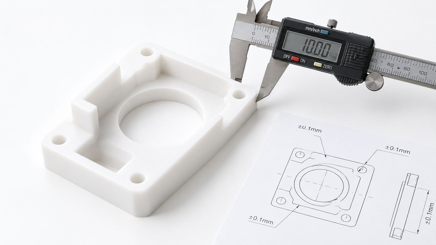
A prototype drawing needs more than a blanket tolerance note. Most parts contain dimensions that can vary without affecting function, alongside a small number that control sealing, alignment, press fits, or snap behavior. Spend inspection effort on the dimensions that change the product decision.
Prototype tooling can be less stable than a durable production mold, particularly when the insert material and cooling behavior differ from the intended production tool. Material shrinkage also varies with resin and process conditions. A drawing tolerance alone can't separate those effects.
Call out what controls function
Identify the few features that directly affect the assembly or performance. For example, measure the sealing land and mating features on a housing separately from non-critical exterior details. Specify datums that reflect how the part is located in the assembly, then define the inspection method with the supplier.
Gate placement, parting lines, weld lines, and ejector marks can affect local appearance and measurement access. A critical cosmetic surface may need a gate or ejector strategy that keeps marks away from the visible area. A tight dimension near a gate or a complex split line deserves a conversation with the toolmaker before the mold is released.
Use a clear inspection plan. Check first shots and later samples, and record the tool condition and process settings alongside measurements. That makes it easier to distinguish normal material shrinkage from tool-induced drift or process variation. Don't interpret a short run as proof that the mold will hold dimensions indefinitely.
For drawing conventions and considerations, consult FIRMFG's injection molding tolerances guide. The useful outcome isn't the largest list of tight tolerances. It's a small, deliberate set of requirements the team can inspect and use to decide whether the design works.
Lead Time and Cost Drivers You Can Actually Forecast
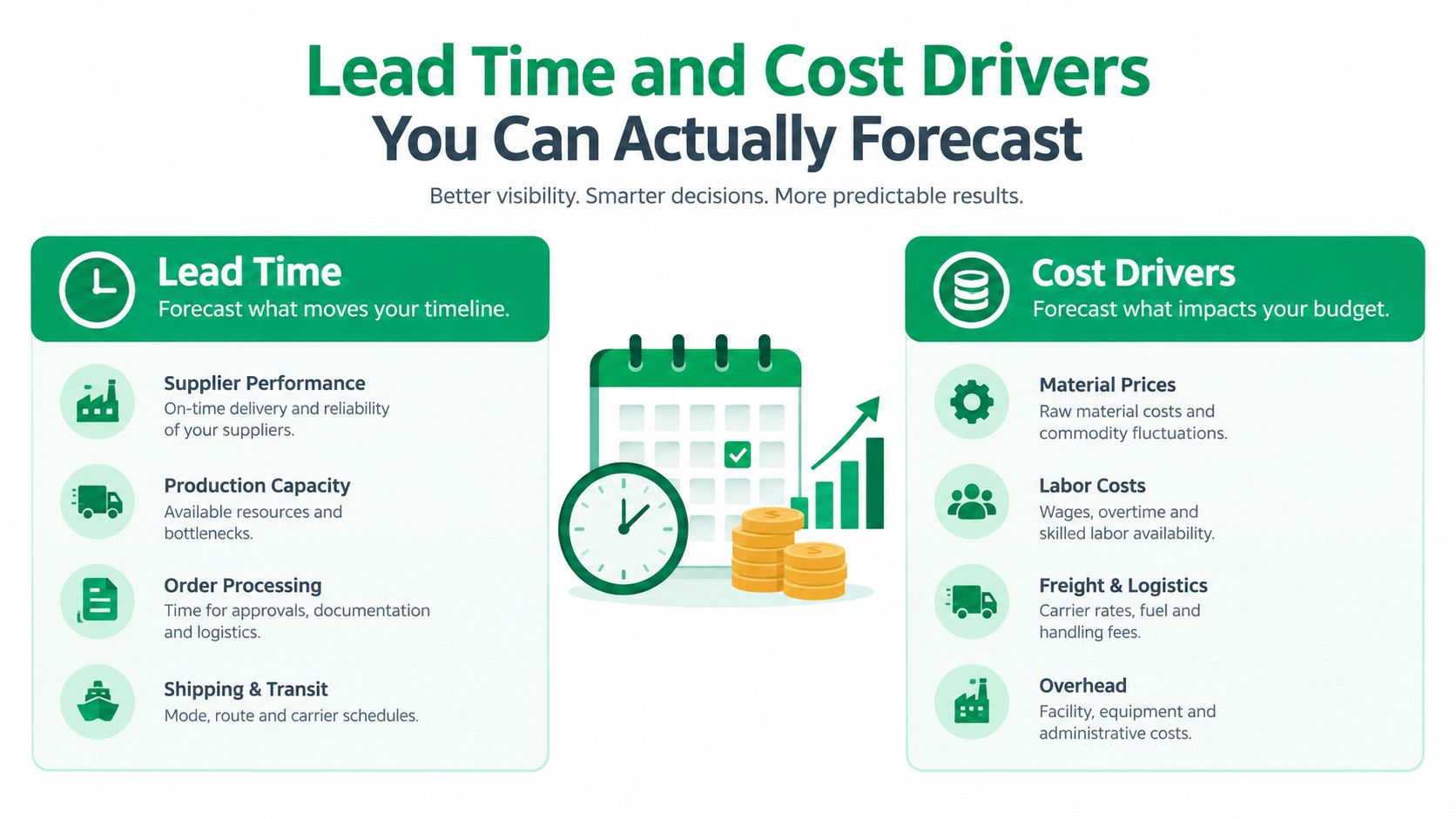
A prototype quote reflects more than the price of cutting a cavity. The tool material, part geometry, cavity count, surface finish, resin, and any secondary operations all affect the work required. A quote also needs to distinguish tooling and sampling costs from the cost of making each part.
Tooling cost is shaped by machining effort, EDM work, access to detailed features, and surface preparation. A complex part may need slides, lifters, or other mechanisms that add design and build effort. Cosmetic expectations can add polishing or texture requirements, while inserts, overmolding, or two-shot construction introduce additional process needs.
Production cost depends on a different set of questions. Cycle time, scrap, inspection, and the number of usable parts all influence the effective cost per part. A low tooling quote may not be economical if the tool cannot reliably make the quantity needed for validation.
Compare the quote on equal terms
Rapid tooling can reduce lead time and resource use compared with conventional steel tooling, but savings only matter alongside tool life and the required shot count. A technical source on 3D-printed injection molds reports 50–90% lead-time savings and 50–70% cost savings, while describing production in thermoplastics at approximately 5–100 parts (technical discussion of 3D-printed injection molds). Those figures don't guarantee the same result for every design or supplier, and a faster tool may not support the quantity or process stability a program needs.
Ask each supplier to quote against the same resin, finish, cavity count, inspection requirements, and expected part quantity. Clarify whether sampling, design changes, and dimensional reporting are included. For a broader breakdown of the factors behind pricing, see FIRMFG's injection molding cost guide.
A useful forecast compares total program cost, not just the tool price. Include the likely cost of a design revision, the value of parts the tool can produce, and whether the prototype process will answer the question that prompted the build.
Design for Manufacturing Tips Before You Cut the Tool
A CAD model can be easy to machine and difficult to mold. Before releasing prototype tooling, review the geometry with the resin and tool construction in mind. The purpose isn't to make every feature ideal for a long production run. It's to avoid preventable defects and give the prototype a fair chance of validating the design.
- Add draft where surfaces release from the tool. Insufficient draft can make parts stick, damage surfaces, or complicate ejection. The required amount depends on material, texture, and geometry, so agree on it with the mold designer.
- Keep wall thickness as consistent as practical. Abrupt changes can contribute to uneven cooling, sink, and warpage. If a design needs a thick boss, review how it connects to the surrounding wall rather than adding material alone.
- Use ribs and bosses carefully. Thick features may create sink or local variation. Shape and support them so they add stiffness without creating a large mass of plastic.
- Discuss gate position early. The gate affects how the cavity fills and where gate marks remain. A preferred cosmetic surface may conflict with the simplest fill path, so decide which trade-off matters most.
- Review likely weld-line locations. Flow fronts can meet around holes or other obstructions. If a weld line lands in a highly loaded region, ask whether the geometry or gate strategy should change.
- Plan how the part will eject. Identify suitable ejector locations and avoid making delicate features carry the ejection load. Recesses and undercuts may require slides or changes to the design.
For a toolmaker review, provide the production-intent resin, expected shot count, critical dimensions, cosmetic surfaces, preferred gate location, and any documentation the prototype must support. If the design is still changing, point out features that may need revision so the supplier can discuss tool adjustments before machining begins.
What a Prototype Can and Cannot Tell You About Production
A clean prototype part doesn't prove that a production mold will hold the same dimensions or appearance over a sustained run. Tool material, cooling layout, cavity count, and repeated thermal cycling all affect how the mold behaves. The prototype is evidence about the design under the conditions tested, not automatic qualification of a future production process.
Some findings transfer well. Teams can use molded prototypes to assess geometry, assembly fit, gate placement, filling behavior, draft, and early mechanical performance. A short run can also reveal whether the intended material appears to meet the immediate design need. But the same result may change when a production tool uses different thermal properties, cooling channels, or process settings.
The risk is assuming that a small batch captures long-term behavior. Additively manufactured inserts can be affected by pressure, thermal cycling, abrasion, and heat removal, while the behavior of a rapid tool may differ from hardened production steel. A prototype run that ends before meaningful tool wear appears can't establish how the mold will perform after sustained use.
Carry evidence into the next tool
Record the resin grade, tool material, cavity temperature, injection and packing settings, cooling approach, cavity count, and inspection results. Track dimensions from early and later samples so the team can identify drift rather than treating one acceptable part as proof of stability. Keep cosmetic observations and defect locations with the corresponding process notes.
Before production release, revalidate dimensions, warpage, appearance, and process capability using the production-intent tool and conditions. For medical, automotive, or precision assemblies, make sure the validation plan addresses the quality requirements of the application. The goal of prototype molding is to reduce uncertainty and improve the next decision, not to claim evidence the build never generated.
FIRMFG supports CNC machining, 3D printing, vacuum casting, and rapid injection molding for prototype and low-volume builds, with DFM feedback and inspection as part of project support. If you're deciding which process can answer your next engineering question, share your part requirements with FIRMFG and request a review of the geometry, material, and validation goals.