Injection Molding with 3D Printed Molds: A Practical Guide
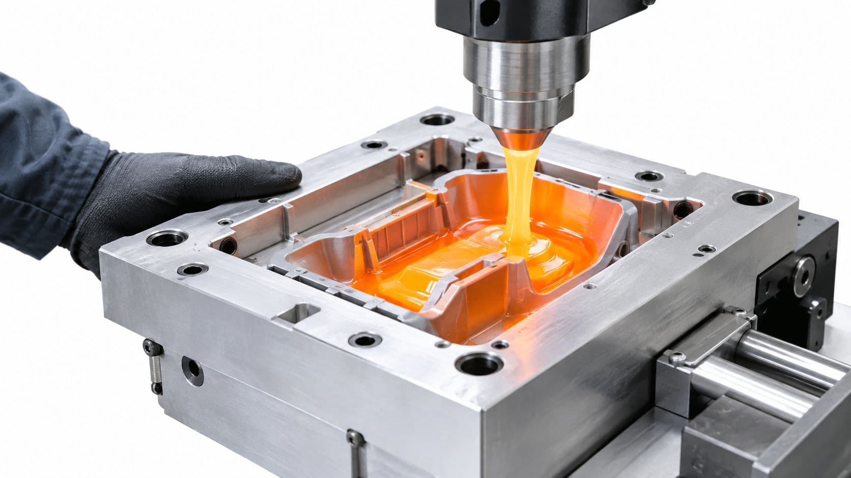
A product team needs functional molded parts for a pilot, but the conventional tooling quote arrives too late and demands more capital than the program can justify. The design may still change after the first real-resin test, so committing immediately to hardened steel creates a second problem: every revision becomes expensive.
Injection molding with 3D printed molds can solve that gap, but only when the tool architecture matches the pressure, temperature, geometry, and required run length. The important decision is not just whether a mold can be printed. It's whether you should print a complete stand-alone mold, print only the core and cavity for an aluminum frame, or skip polymer tooling and move directly to metal.
Table of Contents
Choosing the Right Mold Material and Printing Process- Compare the material families by risk
Designing the Mold for Printability and Pressure- Build the insert around demolding
Setting Injection Parameters That Protect the Tool- Ramp the process instead of guessing
Realistic Mold Life and Cost-per-Part Numbers- Use a break-even model, not a cycle promise
Common Failure Modes and How to Prevent Them- Cracking follows stress concentration
- Flash points to closure or packing problems
- Wear accelerates with abrasive resin
- Thermal lag creates short shots and warpage
Decision Checklist Before You Commit to a Printed Mold
Why Teams Use 3D Printed Molds for Injection Molding
The strongest use case is the uncomfortable space between a printed prototype and a production tool. A team needs molded parts made from the intended thermoplastic, wants to test fit and function under real shrinkage, and can't wait for a conventional tool revision. A printed insert can provide that bridge without forcing the project to absorb the full cost and schedule of permanent tooling.
The economics are meaningful when the alternative is delaying a pilot or funding a tool that may soon be obsolete. A 2024 study on integrating additive manufacturing into the injection-molding process chain found that polymer inserts made by additive manufacturing can reduce production costs by 80 to 90 percent compared with conventional machining-based tooling chains, while reducing lead time by 60 to 70 percent compared with machining brass or aluminum inserts. The study identifies new molded product development as a particularly relevant application, because tooling often dominates the early program cost and schedule. The DTU study on additive manufacturing and production-cost optimization provides the underlying analysis.
That doesn't make a printed mold a cheaper production tool in every situation. The saving often comes from avoided capital, faster iteration, and postponed hard tooling, not from a lower unit cost after a long run.
Where the approach earns its place
A printed mold is usually worth evaluating when:
- The design is still moving: You can validate filling, shrinkage, fit, and assembly before committing to a permanent cavity.
- The requirement is a pilot or bridge run: The parts need to be functional, but the volume doesn't justify a hardened production tool.
- The resin is relatively forgiving: Low-viscosity thermoplastics and moderate processing conditions place less stress on the insert.
- The geometry supports easy demolding: Draft, generous gates, adequate venting, and sturdy cores matter more than printability alone.
- The architecture can transfer load into metal: A framed insert has a better chance of surviving than an unsupported polymer block.
The failure is usually not that the printed cavity can't reproduce the shape. The more common problem is that the tool cracks, wears, flashes, or retains too much heat before the part can be removed. A review of additive injection tooling reports practical lives ranging from 30 to 100 cycles for some molds, while another study found a temperature-resistant thermoplastic mold that exceeded 150 cycles without visible wear. A separate stereolithography micro-molding study recorded 78 cycles before cracking caused insert failure. These results are summarized in the review of additively manufactured injection molds.
| Approach | Typical lead-time position | Tooling cost position | Economic run size |
|---|---|---|---|
| Stand-alone polymer mold | Fastest to trial | Lowest initial commitment | Very short validation runs |
| Printed insert in an aluminum frame | Fast, with better mechanical support | Moderate initial commitment | Low-volume and bridge production |
| Machined aluminum tooling | Slower to build and revise | Higher upfront commitment | Repeated low-volume production |
| Hardened steel tooling | Longest commitment | Highest upfront commitment | Sustained production where tool life matters |
A stand-alone mold can work for a simple part and a cautious trial, but it leaves the printed material responsible for alignment, clamping, pressure, and thermal cycling. An insert-in-frame design gives the polymer cavity a reusable support structure, standard ejector hardware, and a more stable parting relationship. That is why rapid tooling services from FIRMFG are best evaluated around the complete stack, not the printed cavity in isolation.
Choosing the Right Mold Material and Printing Process
Material selection starts with the injection window, not the printer on the shop floor. The mold must tolerate the resin's melt temperature, pressure, viscosity, shrinkage, abrasion, and demolding force at the same time. A resin with excellent heat resistance can still fail if it is brittle at the gate or unsupported around an ejector feature.
For polymer inserts, SLA and other resin-based processes are generally attractive because they can produce smooth molding surfaces and fine details. That surface quality reduces the amount of finishing needed and can make demolding less aggressive. FDM can be useful for fixtures or frames, but layer direction and surface stepping make it a poor default for a cavity that must hold pressure and transfer a controlled finish.
Compare the material families by risk
A general-purpose photopolymer belongs at the low end of the application range. It can be suitable for a geometry check, a few functional shots, or a low-temperature resin when the team accepts that the tool may be consumable. It isn't the right choice for a demanding cavity with thin cores, abrasive filler, or repeated thermal cycling.
High-temperature or filled photopolymers offer a better balance, but they still require validation. Stiffness helps the cavity resist deflection, while toughness determines whether it survives clamping and ejection. A very brittle insert may look excellent after printing and fail suddenly at a sharp corner.
Metal additive manufacturing changes the failure mode. A printed metal insert can handle more pressure and wear than a polymer insert, but it still needs machining, finishing, inspection, and proper support in the mold base. It shouldn't be selected just because the target cycle count is higher. If the part requires a critical parting line, polished surface, or aggressive engineering resin, a machined metal insert may be more predictable.
| Material family | Printer technology | Practical use | Best-fit resin category |
|---|---|---|---|
| General photopolymer | SLA or similar resin printing | Geometry checks and very short trials | Low-temperature, low-viscosity thermoplastics |
| Filled or high-temperature photopolymer | SLA, DLP, or related resin process | Short-run validation and selected low-volume work | Forgiving thermoplastics with controlled pressure |
| Metal insert | Metal additive manufacturing followed by machining | Higher-load short runs and complex insert geometry | Engineering thermoplastics, subject to process validation |
| Machined metal insert | CNC, EDM, or hybrid manufacturing | Repeatability, wear resistance, and longer production use | Broadest resin and process window |
The practical rule is to compare the insert's validated heat-deflection behavior with the complete molding cycle, not only the barrel setting. The cavity sees heat during filling, packing, cooling, and ejection. It also sees localized stress at the gate, thin cores, corners, and ejector points.
The SLA and SLS process comparison from FIRMFG is useful when deciding whether surface quality, structural behavior, or frame construction should drive the print-process choice. Whatever process you select, over-specify the tool when the consequence of failure is a missed pilot build. Print spare inserts for fragile features, and treat the first tool as a process-development asset rather than a guaranteed production mold.
Designing the Mold for Printability and Pressure
A printed cavity should be designed like a pressure-bearing component, not like a cosmetic prototype. The part geometry still needs conventional injection-molding fundamentals, but the tool itself needs additional support around the gate, parting line, cores, and ejector system.
Start with the architecture. For most runs beyond a basic fit check, print only the cavity and core, then install them in a reusable aluminum frame. The frame should carry clamping and alignment loads, while the printed insert provides the molding surface. Stand-alone polymer molds can be useful for simple parts, but they expose the printed material to every load at once.
Build the insert around demolding
Draft is cheap insurance. Add enough draft that the part releases without forcing the ejector system to pull against a rough or thermally swollen surface. Thin standing cores, deep pockets, sharp internal corners, and undercuts all multiply the risk of cracking during ejection.
Keep insert walls thick enough to resist bending and local heat distortion. Avoid unsupported slabs and narrow sections that follow the part geometry too closely. Ribs on the back of the insert can add stiffness, but they should transition smoothly into the main body. A sharp rib intersection becomes a stress concentrator, especially when the print orientation places a weaker direction through the feature.
Practical rule: If a core looks fragile before injection, assume demolding will make it weaker, not stronger.
Gates deserve more attention than they usually receive in printed tooling. An edge or tab gate gives the tool a broader, more stable land and distributes the entry load. A small tunnel gate creates a thin feature that can chip, flare, or concentrate heat and pressure. Open the gate enough to fill without excessive pressure, and add vents that let displaced air escape instead of forcing the melt to compress it into the parting line.
Choose support before adding complexity
Cooling is the difficult trade-off. Polymer inserts have lower thermal conductivity and lower thermal mass than metal, so the cavity can heat quickly and cool slowly. Conformal channels may help in some metal or advanced hybrid tools, but channels also weaken polymer inserts and complicate printing, sealing, and cleaning. Don't add them automatically. First determine whether the process can use longer cooling, interchangeable inserts, external temperature control, or a slower shot.
A peer-reviewed comparison of printed inserts with a conventional duralumin mold found the printed route produced tensile results almost 15 percent better in the reported specimens, while the temperature simulation matched the experiment within 5.36 °C. Those results don't remove the need for design validation, but they show that a printed tool can be technically viable when thermal behavior and mechanical stress are controlled. The published comparison of 3D-printed molds and conventional tooling is a useful reference for that validation mindset.
Before printing, add stock where critical faces may need finishing. Plan how you'll machine or sand the parting line, gate, vents, ejector holes, and frame interfaces. A printed mold that cannot be measured and corrected is not a finished tool.
Setting Injection Parameters That Protect the Tool
The first shots should be treated as a controlled load test. A steel mold can tolerate aggressive filling and rapid cycling because it has high stiffness and conducts heat away from the cavity efficiently. A printed insert can't be assumed to have the same margin.
Begin with the lowest practical melt temperature for the selected resin and the lowest pressure that fills the cavity. A high melt temperature can reduce viscosity, but it also increases thermal exposure. More pressure may hide a venting or gate problem for a few shots, then open the parting line or crack the insert.
Ramp the process instead of guessing
A cautious start-up sequence looks like this:
- Run an empty clamping check. Confirm that the insert seats fully in the frame, the parting line closes evenly, and the ejectors don't contact a fragile feature.
- Make the first fill incomplete. Use reduced speed and pressure to observe the flow front, gate behavior, venting, and insert movement.
- Increase fill gradually. Change one parameter at a time. If the cavity fills only after a large pressure increase, improve the gate or vent instead of forcing the tool.
- Add hold pressure carefully. Use only enough packing to control sink and dimensional behavior. Over-packing raises cavity stress and encourages flash.
- Extend cooling before increasing speed. Thermal lag is often the bottleneck. A faster shot doesn't solve a tool that hasn't released its heat.
- Inspect the insert after every early shot. Look for whitening, hairline cracking, new flash, gate erosion, and movement at the frame interface.
For the first 25 shots, record the fill condition, peak pressure, hold response, cooling time, part weight, ejection force, and insert temperature. Divide the run into five-shot checkpoints. Stop if the parting line changes, the gate begins to deform, or a crack appears. A printed insert can fail progressively, but it can also break during the next ejection cycle without a visible warning.
| Parameter | Printed polymer insert | Conventional steel mold |
|---|---|---|
| Melt temperature | Use the low end of the validated resin window | Wider process window |
| Injection pressure | Keep as low as the fill allows | Higher pressure is generally tolerated |
| Injection speed | Moderate and controlled | Faster filling is often practical |
| Hold pressure | Minimize excess packing | More robust against over-packing |
| Cooling | Longer and actively monitored | Faster heat transfer |
| Demolding | Gentle, with attention to adhesion and ejector load | More tolerant of repeated ejection |
| Process monitoring | Inspect tool condition frequently | Focus mainly on part and process variation |
The low-volume rapid injection molding study from Formlabs reports a printed mold surviving approximately 1,500 to 2,500 injection cycles before breakage in a specific low-volume application. It also reports 90 to 94 percent time savings and 80 to 97 percent cost savings versus the alternatives used in that project. Those results came from a favorable geometry and process, so they should be treated as evidence of possibility, not a default specification for every printed insert.
Realistic Mold Life and Cost-per-Part Numbers
Mold life is where optimistic guidance causes the most damage. A printed insert doesn't have one universal cycle rating because the result depends on geometry, support, resin, gate design, pressure, thermal exposure, filler, surface treatment, and how carefully the operator demolds each part.
The academic record spans a wide range. Some polymer tools last only dozens of cycles, while carefully supported inserts and simple geometries can run into the hundreds or beyond. The same review that describes 30 to 100 cycles for some additively manufactured molds also reports a temperature-resistant thermoplastic tool exceeding 150 cycles, and a separate study recorded 78 cycles before cracking. These figures don't conflict. They describe different tool stacks and operating conditions.
Use a break-even model, not a cycle promise
The right calculation includes more than the printed material. Add:
- Tool preparation: Printing, washing, post-curing, finishing, inspection, and frame assembly.
- Machine time: Injection, cooling, manual demolding, and any tool-change time.
- Scrap exposure: Early process development may produce unusable parts while the operator finds a stable window.
- Replacement inserts: Fragile cores or parting features may need spares.
- Finishing labor: Gate trimming, flash removal, sanding, polishing, and dimensional inspection.
- Opportunity cost: A rapid tool loses value if its long cooling cycle occupies a machine needed for other work.
| Mold material or architecture | Cycle-life expectation | Amortized mold cost | Cost per part at 500 units | Cost per part at 5,000 units |
|---|---|---|---|---|
| Basic polymer, stand-alone | Must be established by trial | Low initial commitment, but replacement risk is high | Can be reasonable only if the tool survives the run | Usually requires replacement or a different tool |
| Filled polymer insert in a frame | Geometry and resin dependent | Moderate initial commitment | Often suitable for validation and selected low-volume work | Requires a verified life and replacement plan |
| Metal printed insert | Higher resistance than polymer, after finishing | Higher initial commitment | Can make sense when wear or temperature rules out polymer | Compare directly with machined aluminum or steel |
| Machined aluminum insert | Predictable for repeated low-volume work | Higher initial commitment | May be excessive for a short validation run | Often becomes more attractive as repetition increases |
No responsible cost-per-part figure can be calculated without the actual part mass, press rate, labor burden, scrap rate, insert cost, and number of replacement tools. A claimed unit price without those inputs is only a quote for a scenario, not an engineering result. The injection molding cost overview from FIRMFG can help structure that comparison, but your own process assumptions still control the decision.
A practical break-even exercise compares three options at the target quantity: a framed printed insert, machined aluminum, and a conventional production tool. Include the cost of a failed trial and the time value of getting parts earlier. If the printed tool requires repeated replacement, slow manual demolding, or extensive finishing, its low build price may disappear quickly.
The most useful question isn't, “How many parts can this mold make?” Ask, “What is the total cost of delivering the required good parts, including the tool failures and operator time that the optimistic estimate leaves out?”
Common Failure Modes and How to Prevent Them
A printed mold failure is usually diagnostic. The damaged area often shows whether the problem started with thermal stress, excessive pressure, poor alignment, abrasion, or an ejection load that the architecture couldn't carry.
Cracking follows stress concentration
Hairline cracks near gates, ejector holes, thin cores, and layer transitions indicate local stress rather than a random material defect. Reduce thermal and pressure exposure, improve the support around the feature, enlarge the gate, and remove sharp transitions. If the print orientation puts a weak direction through a loaded section, change the orientation or replace that feature with a machined metal insert.
Don't wait for a visible break before acting. Whitening, a new line in the surface finish, or a change in ejection force can be the first warning.
Flash points to closure or packing problems
Flash can come from a parting line that wasn't finished flat, an insert that shifted in the frame, insufficient clamping, or a cavity packed harder than the tool can contain. Sanding the parting line may help, but it won't fix a frame that doesn't support the insert or a gate that forces excessive pressure.
Check the frame, alignment, venting, and hold pressure in that order. Removing flash from every part is not a process control strategy.
Wear accelerates with abrasive resin
Glass-filled or mineral-filled thermoplastics can erode gates, vents, and textured surfaces. A coating or harder insert may extend useful life, but coatings also change dimensions and can chip at sharp edges. Validate the finished surface after treatment, especially around the gate and parting line.
Thermal lag creates short shots and warpage
A cold cavity can freeze the flow front before the part fills. A hot cavity can hold the part against a soft insert and make ejection destructive. Preheat consistently, monitor the tool rather than relying only on barrel settings, and extend cooling until the insert reaches a repeatable release condition.
| Symptom | Likely cause | Prevention or fix |
|---|---|---|
| Hairline crack at gate | Local pressure and thermal stress | Enlarge gate, reduce process severity, reinforce or replace insert |
| Crack around ejector feature | Ejector load or thin section | Increase support, improve draft, reduce ejection force |
| Flash at parting line | Poor fit, insert movement, or over-packing | Finish and align the parting line, support the insert, reduce hold pressure |
| Short shot | Cold cavity, restricted gate, or inadequate venting | Improve preheating, open the gate, add venting, extend fill time |
| Warped part | Uneven tool temperature or premature ejection | Stabilize temperature, allow more cooling, inspect frame support |
| Surface wear | Abrasive filler or repeated demolding | Use a more resistant insert or validated surface treatment |
| Part sticks | Insufficient draft or rough cavity | Add draft, polish the release path, use a compatible release aid |
Decision Checklist Before You Commit to a Printed Mold
Review the part, resin, and volume as one system. A low-temperature resin in a simple geometry may be a good framed-insert candidate, while a smaller part with abrasive filler and a delicate core may be a poor candidate despite its low shot size.
Use this checklist before approving the print:
- Required cycle count: Is the target within a validated life range for this exact insert material and geometry?
- Resin behavior: Is the material low enough in viscosity and temperature exposure to protect the insert?
- Part geometry: Are the cores, ribs, corners, and walls sturdy enough for injection and ejection?
- Draft: Can the part release without levering against the cavity?
- Gate location: Does the gate use a strong, accessible region rather than a fragile tunnel feature?
- Venting: Can air escape without forcing flash or burn marks?
- Architecture: Will an aluminum frame carry the clamping and injection load?
- Thermal control: Can the team preheat, cool, and monitor the insert consistently?
- Finishing capability: Can the parting line, gate, vents, and ejector interfaces be corrected after printing?
- Inspection plan: Will the team measure the first parts and inspect the tool at defined intervals?
- Replacement strategy: Are spare inserts available for fragile cores and expected wear points?
- Economic comparison: Has the team compared total delivered-part cost with aluminum or steel tooling?
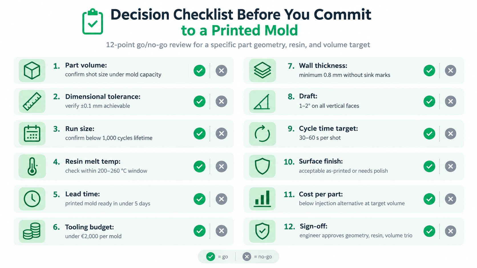
Use the results to choose the architecture, not just to approve or reject printing. A stand-alone polymer mold belongs to a cautious, short validation trial with a simple part. A framed printed insert is the default choice when the part needs meaningful functional testing or repeated low-volume production. Move to machined aluminum or steel when the run, resin, tolerance, abrasive content, or cosmetic requirement exceeds the validated polymer window.
A useful research example supports that nuanced decision. A low-volume study reported tool breakage as the limiting failure rather than poor molded-part quality, while also identifying degraded thermal performance, lower surface quality, and post-processing as practical constraints. The lesson is straightforward: printability proves that a tool can be made. It doesn't prove that the tool can survive your injection window.
FIRMFG can help evaluate whether your part is better suited to an SLA insert, a framed rapid tool, or conventional injection molding through DFM review and low-volume manufacturing support. Share your CAD model, resin, target quantity, and tolerance requirements by visiting FIRMFG.