Fused Deposition Modeling Explained for Engineers
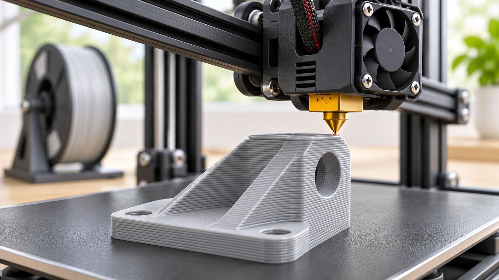
The printed bracket looks right on your desk. Then you bolt it against a machined plate, the holes resist alignment, and a mounting ear cracks as you tighten the screw. Before changing the CAD or rejecting the plate, check what the print represents. A convincing shape isn't necessarily reliable evidence of fit, stiffness, or strength.
Table of Contents
How Filament Becomes a Layered Part- The deposition sequence
Filaments for Functional Prototypes- Match the job, not just the polymer name
Strength and Accuracy Limits- Distinguish continuous roads from interfaces
Prototype Jobs FDM Handles Well- Concept and assembly work
Design Rules for a Trustworthy Prototype- Reorient the bracket before increasing infill
Choose FDM or Move to Another Process- Choose the process that makes the test credible
What Fused Deposition Modeling Is
Fused deposition modeling builds a part by melting solid thermoplastic filament and depositing it through a heated nozzle along computer-controlled paths. Each deposited strand, usually called a road or bead, contributes to a layer. Successive layers turn the digital geometry into a physical object without a mold.
That distinction matters for the bracket on your bench. The printer hasn't reproduced the internal structure of a molded bracket. It has reproduced the external geometry using a particular arrangement of extruded material, seams, and interfaces.
From industrial invention to desktop tool
Scott Crump reportedly developed the idea while making a toy frog with polyethylene and candle wax in 1988; the subsequent 1989 patent filing became U.S. Patent No. 5,121,329, according to MakerBot's history of 3D printing. Stratasys began selling commercial systems in 1992, with early machines reportedly costing approximately $200,000. This was industrial prototyping equipment before it became a familiar desktop tool.
FDM is a Stratasys trademark. The broader standards-based process family is material extrusion, while non-Stratasys and open-source filament systems commonly use fused filament fabrication, or FFF. They share the basic melt-and-deposit principle, although machine control, material qualification, and repeatability can differ substantially.
The expiration of key early patents in 2009 helped open the way for lower-cost extrusion printers and community-developed hardware and software, as described in MIT's material-extrusion overview. Engineers gained a practical route from CAD to a physical iteration without committing to tooling.
Start with the question: Are you checking the shape, the assembly, or the loaded behavior? Those are different prototype requirements.
FDM remains commercially significant: Mordor Intelligence valued the global FDM 3D-printer market at USD 2.7 billion in 2025. That market size doesn't establish suitability for your bracket. The useful engineering decisions concern the deposition sequence, filament, build direction, and acceptance criteria.
How Filament Becomes a Layered Part
A slicer does more than convert a solid into machine motion. It decides where material goes, which regions remain hollow, where supports touch, and how the machine sequences deposition. Start troubleshooting with that manufacturing plan rather than the rendered preview.
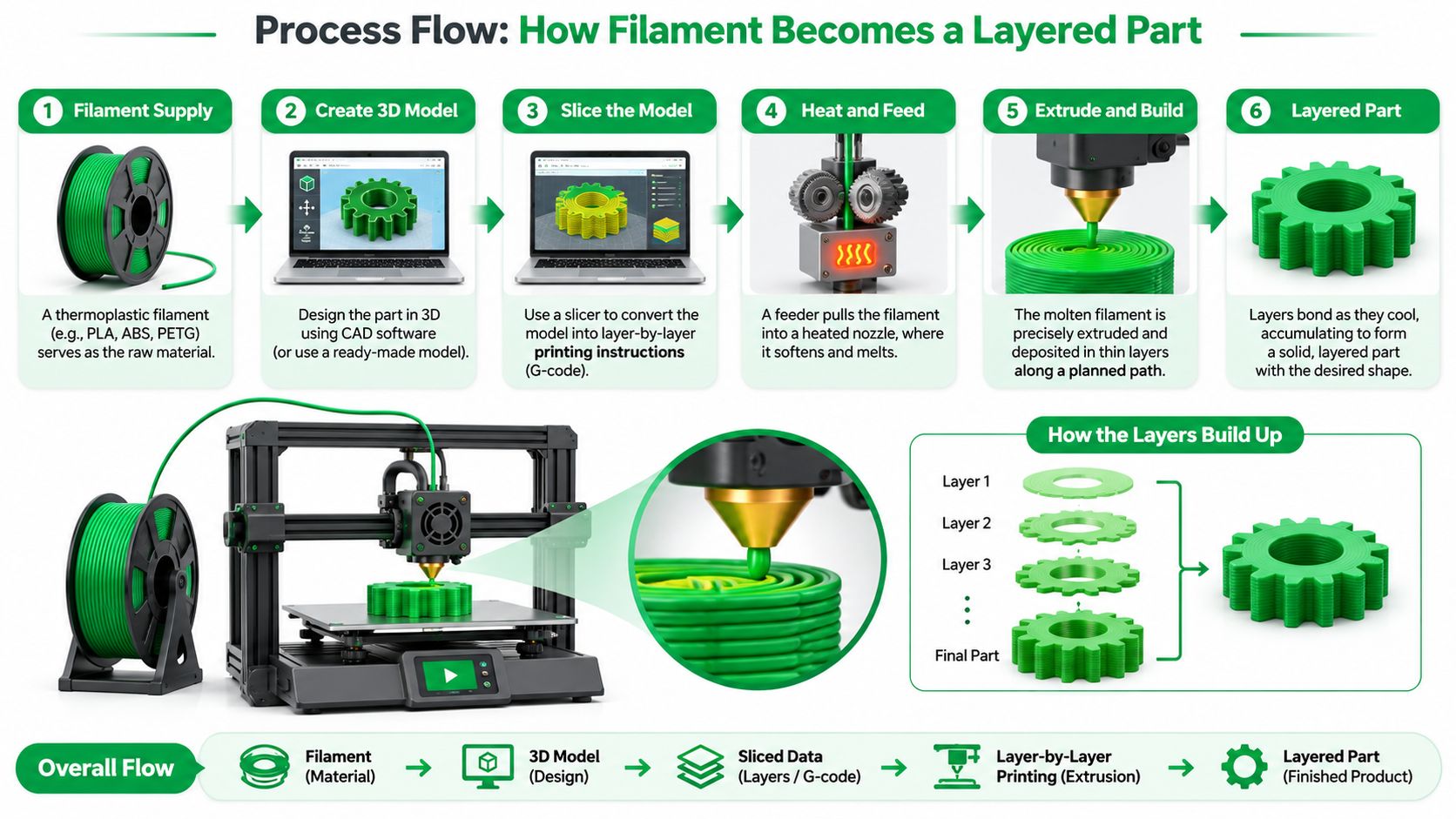
The deposition sequence
- Prepare and slice the solid. Export a watertight model, select layer height, extrusion width, walls, infill, and supports, then inspect the toolpath because missing faces or unresolved thin features can produce missing material. Check section views through bosses and mounting ears, not just the outside silhouette.
- The drive mechanism pushes filament into the hot end, where it becomes a viscous melt; insufficient melting or restricted feeding causes under-extrusion. Use a material profile compatible with the actual hot end, rather than borrowing settings solely because the spool carries the same polymer abbreviation.
- Deposit roads rather than a poured volume. The nozzle traces walls and internal raster paths in the order selected by the slicer, and poorly planned starts, stops, or extrusion transitions can leave seams and local voids. Some profiles print outer walls first; others prioritize internal walls or infill.
- Fresh material contacts the preceding surface and cools into place; excessive heat causes sagging, while inadequate interface temperature produces poor fusion. Cooling must preserve unsupported geometry without prematurely chilling the surfaces that still need to bond.
- Advance along the build axis. The printhead or platform moves by the selected layer increment, depending on machine architecture, and an inconsistent increment can cause nozzle interference or poorly compressed roads. The bed doesn't necessarily descend on every printer.
- Add supports, a brim, or a controlled enclosure where geometry and shrinkage require them; unsupported material can droop, while lifting corners can spoil the entire datum surface. Inspect support access before starting, especially inside enclosed passages.
Read the preview like a manufacturing drawing
The finished part is closer to a stack of welded beads than a miniature injection molding. A hot-glue gun following a toolpath is a useful mental model, provided you remember that engineering thermoplastics demand much tighter thermal control.
Look for interrupted load paths, isolated islands, unsupported roof surfaces, and seams on contact faces. A smooth shaded model hides all of these.
The slicer directly controls bead paths and the placement of layer boundaries, while its temperature, speed, and cooling commands influence thermal history. Actual interface temperatures also depend on the machine, enclosure, geometry, and surrounding conditions. A correct toolpath is necessary, but it isn't the whole process.
Filaments for Functional Prototypes
FDM filaments for prototype decisions
| Filament | Warp risk | Useful heat band | Choose it for | Poor fit |
|---|---|---|---|---|
| PLA | Low | Cool service; verify loaded-temperature performance | Fast concept and fit models | Loaded or warm parts |
| ABS | High; needs enclosure | Elevated-temperature service within the grade's validated limit | Tough indoor housings | Uncontrolled open-frame printing |
| ASA | High; needs enclosure | Grade-qualified outdoor and warm service | UV-exposed fixtures | Fine cosmetic detail without finishing |
| PETG | Moderate | Ambient and moderately warm service after testing | Jigs, guards, compatible fluid splash | High-heat under-hood parts |
| Nylon (PA) | Significant; moisture adds instability | Verify the conditioned grade under load | Clips, wear, toughness | Uncontrolled humidity |
| Polycarbonate | Very high | Higher-temperature service with grade validation | Impact and higher heat | Quick desktop trials |
| TPU | Low to moderate | Validate the grade under sustained deformation | Grips, bumpers, flexible clips | Unqualified pressure seals |
| Carbon-fiber nylon | Lower than neat nylon | Follow the nylon base and conditioned test results | Stiffer brackets and tools | Layer-opening loads; brass nozzles |
Match the job, not just the polymer name
A useful heat limit isn't a single universal temperature for a polymer family. Load duration, stress, moisture, formulation, and the acceptance criterion all matter. A housing that survives a brief warm exposure may still creep when a fastener holds it under sustained stress.
PLA is a sensible first article when the question is packaging or accessibility. A PLA prototype can reveal whether a connector clears a wall, but it doesn't validate the repeated flexing of a production ABS latch. Material substitution changes the question the test can answer.
PETG is a practical starting point for general-purpose jigs and guards. It offers useful toughness without the same enclosure demands as ABS, but stringing can obstruct small clearances and contaminate seating surfaces. Remove those defects before deciding the geometry is wrong.
ABS and ASA require attention to shrinkage and enclosure stability. Choose ASA when weathering and sunlight matter, rather than assuming an indoor housing material will behave the same outdoors. Neither choice eliminates the need to test the printed assembly.
Moisture and reinforcement change the setup
Nylon needs controlled drying and storage. Wet filament can produce bubbling, rough extrusion, and compromised interfaces, so adjusting flow isn't an adequate substitute for restoring material condition.
Polycarbonate suits demanding heat and impact questions only when the printer can maintain the required environment. TPU serves grips and compliant bumpers, but flexibility alone doesn't establish leak tightness or sealing reliability.
Chopped-carbon-fiber nylon can improve stiffness and dimensional stability. It also requires a wear-resistant nozzle, and the fibers don't create continuous reinforcement through the layer stack.
If the bench test involves heat, impact, or chemical exposure, identify the filament grade and conditioning state on the drawing.
Strength and Accuracy Limits
An FDM part is a stack of welded roads, so strength depends on direction. Adjacent roads and layers join through heat transfer, wetting, polymer diffusion, and cooling. They aren't a homogeneous volume whose properties can be represented by a single bulk-polymer number.
A PLA investigation published in the Journal of Materials Engineering and Performance identified printing angle and layer height among the most influential tensile-property variables, with predictive models achieving coefficients of determination above 0.90. The practical implication is that process settings are part of the material specification, not merely production preferences.
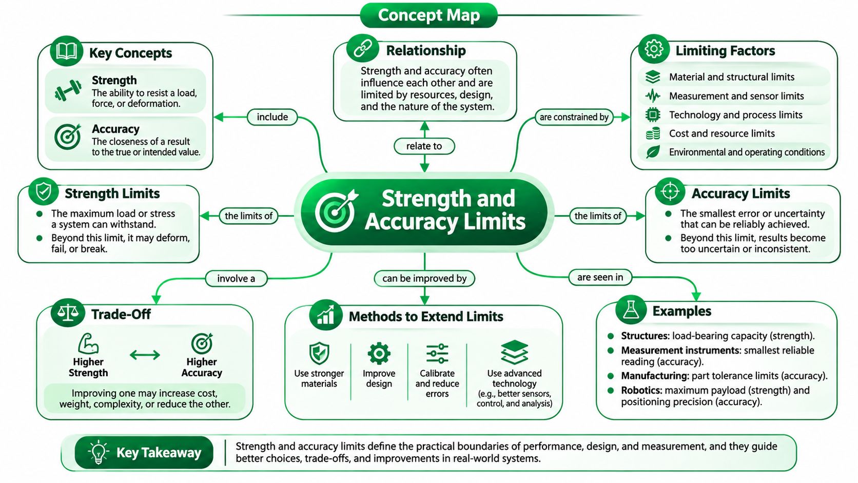
Distinguish continuous roads from interfaces
Along a continuous road, the polymer carries load without repeatedly crossing deposition interfaces. Across adjacent roads, fusion quality and gaps become more important. Loads that pull layers apart are particularly sensitive to interlayer bonding and can produce delamination.
Don't turn that pattern into an absolute strength ranking for every geometry. Holes, notches, raster changes, and local cooling can shift where failure begins. A bracket may fail at a seam or thin ligament before its nominal build-axis weakness becomes decisive.
For a bending member, inspect the tensile surface rather than aligning the part with the force arrow alone. The mounting constraint and lever arm determine where tensile stress develops. A favorable orientation for the base plate may be unfavorable for an upright mounting ear.
Strength settings also affect geometry
Wall thickness, raster direction, line width, temperature, speed, and internal gaps interact. Adding infill doesn't repair a poorly fused perimeter, and raising nozzle temperature to improve fusion may worsen an unsupported face. Changing settings for strength can therefore invalidate dimensions established with an earlier profile.
Accuracy isn't the advertised motion resolution. A printer may position its nozzle consistently while the deposited polymer spreads, contracts, or lifts. Hole size, flatness, and the location of a supported face can respond differently within the same build.
Use separate acceptance criteria:
- Dimensional acceptance. Measure the actual datums and mating features after the part has cooled and been conditioned.
- Mechanical acceptance. Test a representative build under the intended load path, restraint, and environment.
- Process acceptance. Record the setup so a replacement part represents the same manufacturing condition.
A successful fit check doesn't establish durability. Equally, a failed fit check doesn't automatically condemn the mating CNC or molded part. Measure both components before changing either design.
Prototype Jobs FDM Handles Well
FDM earns its place through practical iteration, not universal process superiority. Market.us reports that fused deposition modeling represented more than 44.8% of the global 3D-printing technology market in 2024. For a design engineer, the more useful question is which decision a print will support.
Concept and assembly work
The envelope model. Say you're packaging a motor, cable connector, and service cover inside a compact enclosure. A PLA shell lets the team check hand access, connector insertion, and tool clearance before committing to detailed manufacturing geometry. It needn't reproduce production strength to answer those questions.
The assembly model. A revised housing can expose an inaccessible screw, an awkward cable bend, or a clip that can't reach its mating edge. Keep dimensional acceptance separate from assembly sequence: forcing a screw through an undersized printed hole doesn't establish that the nominal CAD clearance is inadequate.
These are low-risk uses because the print is evidence of space and access, not proof of long-term mechanical performance.
Tooling and early functional work
The workstation aid. A PETG locator or reinforced-nylon nest can support an awkward component during assembly. Put replaceable metal bushings where drill contact would wear a polymer guide, and use hard stops or inserts where repeated clamping would crush the printed surface. A reprintable tool still needs a defined inspection point.
The loaded prototype. A sensor bracket or protective housing can be a valid functional article when the material, orientation, and environment match the test intent. Apply the actual restraint and loading arrangement rather than squeezing it by hand and calling it strong.
A prototype is useful when its failure or success answers the intended question. Convenience alone doesn't make it representative.
Some parts should leave ordinary FDM early. An optical cover needs an appropriate optical manufacturing route. A pressure-tight manifold needs a qualified containment strategy, while a living hinge intended to represent polypropylene needs production-relevant flexural behavior.
Automotive and medical teams can use FDM effectively for fixtures, packaging studies, and design validation without treating those builds as automatically suitable for regulated hardware. Flight parts, implants, and production-approval components require application-specific material and process controls.
Before sending the next file, classify it: envelope model, assembly check, workstation aid, or loaded prototype. That classification should determine the build specification and the test.
Design Rules for a Trustworthy Prototype
FDM design rules for functional prototypes
| Feature | Practical rule | Why it fails otherwise |
|---|---|---|
| Wall thickness | Use multiple continuous roads; inspect thin sections in the slicer | Single beads can split and leak |
| Overhang | Support faces beyond the validated self-supporting angle | Unsupported faces sag or scar |
| Vertical hole | Leave finishing allowance or calibrate compensation with a hole coupon | Deposited roads can leave the hole undersize |
| Horizontal hole | Use a self-supporting profile or finish-machine critical bores | Stepped upper surfaces distort roundness |
| Load direction | Align principal tensile paths with continuous roads where possible | Layer-opening loads promote delamination |
| Layer height | Select for critical slopes and features, then validate the profile | Fine layers add time; coarse layers can obscure fit |
| Walls and infill | Establish continuous load-carrying walls before adding internal fill | Infill alone doesn't resolve local edge stresses |
| Drawing callout | Material, layer height, nozzle, raster, infill, build axis, conditioning | A generic material name doesn't define the printed part |
Reorient the bracket before increasing infill
Consider an angle bracket printed upright on its base. A lateral load at the upper mounting hole bends the upright and can open layer interfaces near its root. Increasing internal fill may make the part heavier without addressing that failure path.
Rotate the bracket onto its side and inspect whether perimeter roads can follow the loaded profile continuously. Then check the consequences: hole orientation, support contact, bed contact, and the location of the critical mounting face. A structurally useful rotation can still create an unacceptable supported datum.
Use a generous root fillet where the design allows it, but don't assume a fillet compensates for an unsuitable build direction. Inspect the actual paths through that transition.
Calibrate the features that decide acceptance
A literature review of FDM dimensional accuracy identifies refined meshes, controlled nozzle temperature, slower printing, reduced layer height, and orientation-specific planning as recurring routes to improved accuracy. It also reports that a 45° orientation can favor many linear dimensions, while horizontal or vertical orientations can benefit radial dimensions. Those are planning findings, not universal correction factors.
Smaller layers reduce staircase error on inclined surfaces, but require additional deposition passes. Use them where the surface or feature justifies the time, not as a blanket remedy for every dimensional problem.
Print a coupon containing the actual hole, boss, slot, or seating feature that determines acceptance. Use the same material condition and machine setup as the intended part, then measure it with the appropriate pin gauge, micrometer, or surface reference.
- Before slicing. Identify critical datums, load paths, and dimensions on the drawing.
- Before testing. Remove supports and distinguish intended finishing from accidental hand fitting.
- Before release. Preserve the build specification and inspection results with the prototype revision.
Plan drilling, sanding, and other 3D-printing post-processing before setting the acceptance criteria. A drilled hole validates the finished hole, not the printer's as-built hole capability.
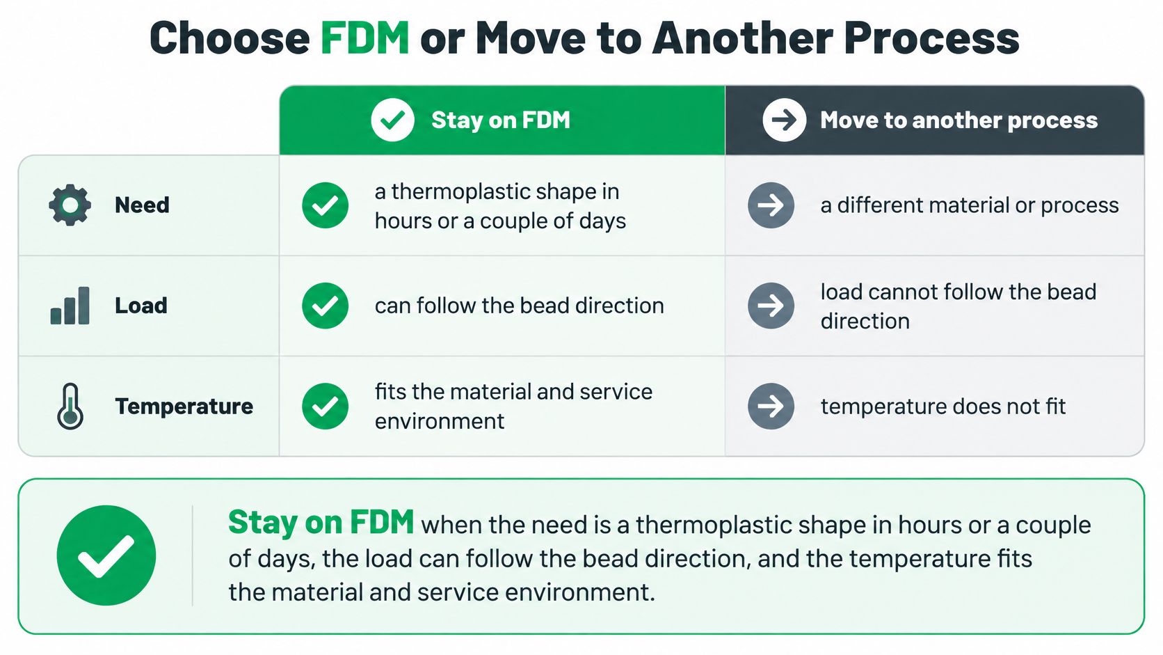
If a critical datum falls on a seam or an unsuitable layer face, reorient or change the finishing plan before arguing about the mating component.
Choose FDM or Move to Another Process
When to keep FDM or change process
| You need to prove | Stay or switch | Why |
|---|---|---|
| Shape, fit, or a simple thermoplastic bracket | Stay with FDM | Direct filament processing supports economical iteration |
| Cosmetic surfaces or very fine features | Switch to SLA or PolyJet | Extruded roads constrain finish and detail |
| Tougher nylon with fewer support marks | Consider SLS | A powder bed avoids attached support structures |
| Tight datums, threads, or metal-like flats | Switch to CNC | Cutting provides direct control of critical surfaces |
| Several production-like plastic copies | Switch to vacuum casting or molding | A different forming process may better represent appearance and flex |
Choose the process that makes the test credible
Stay with FDM when a thermoplastic model can answer the question, its load path is compatible with the build, and its service environment suits the selected filament. Don't retain it merely because the printer is available.
Consider SLS 3D printing for complex nylon geometry where attached supports would obstruct access or mark functional faces. SLS still requires material qualification and dimensional verification; switching processes doesn't remove engineering acceptance work.
Choose CNC when the prototype must represent a machined production component or when contact surfaces dominate the test. For replicated plastic parts, distinguish vacuum-cast simulation materials from the actual injection-molding resin before interpreting flex or impact results.
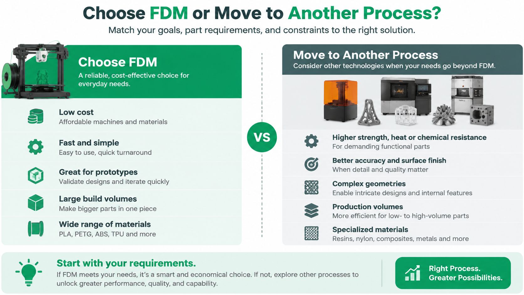
At FIRMFG, we offer FDM, SLA, SLS, SLM/DMLS, and PolyJet, alongside CNC machining, so the process choice can follow the engineering requirement. Our engineers also provide free DFM feedback to optimize designs for CNC machining when extrusion isn't suitable.
Mark the critical dimensions and load axis before submitting the model. Request FDM only when the resulting build will provide meaningful evidence; otherwise specify the alternative process and explain what the prototype must prove.
FIRMFG offers additive manufacturing and CNC machining for prototypes that need to demonstrate more than appearance. Visit FIRMFG with your CAD file, critical datums, material requirements, and load direction to request a build matched to the engineering test.