3D Printing Post Processing Guide for Better Parts
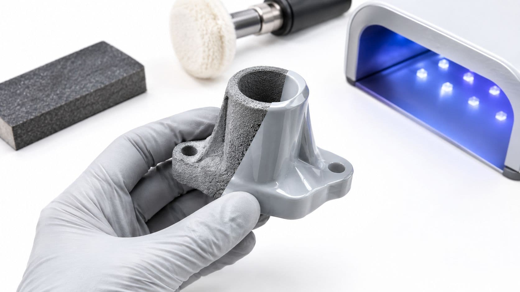
Your prototype has just come off the printer. The geometry looks right, the assembly appears to fit, and the team is ready for testing. Then a support scar interferes with a seal, a rough face changes how a bearing sits, or a resin part fails because it wasn't fully washed and cured. The printed shape was acceptable, but the part was not ready.
That gap is where 3D printing post processing matters. Finishing isn't a cosmetic cleanup performed after the engineering work. It's the bridge between an additive manufacturing process and the surface, strength, dimensional, and appearance requirements your product has.
Table of Contents
- Why Your Print Is Not Your Part Yet
- Understanding 3D Printing Post Processing Fundamentals
Five job families
Process by Process Workflows for FDM SLA SLS and Metal AM- FDM
Achieving Your Target Surface Finish From Ra to Cosmetic- Choose the method by the defect
Dimensional Accuracy Inspection and Material Constraints- Match inspection to the question
Designing to Reduce Post Processing Cost Time and Rework- Prevention decisions for NPI
Putting Post Processing to Work for Production Ready Parts
Why Your Print Is Not Your Part Yet
A bracket leaves the printer with the correct CAD envelope, but the test fixture exposes a support scar beside a mounting face. Sanding hides the mark, then reduces material around a hole. The next print uses a new orientation, while the schedule absorbs the rework. This NPI handoff shows why a printed shape is only an intermediate condition.
Layer lines, support interfaces, trapped powder, uncured resin, residual stress, and heat-affected surfaces remain part of the build history. They may be acceptable on a visual mock-up, yet interfere with sealing, sliding, cyclic loading, assembly fit, or repeated handling.
The finished condition should be defined before the build starts. Specify which faces need a controlled surface, which edges may retain printed texture, where supports can touch, and which dimensions require inspection after curing, blasting, sanding, or machining. Orientation and support strategy then become design decisions that influence Ra, cost, lead time, and rework before finishing begins.
A useful mental model is a rough casting. The machine establishes the main form, while later operations prepare interfaces and verify acceptance. Additive manufacturing follows the same path:
- Removal and cleaning clears supports, powder, resin, rafts, and loose debris.
- Curing and thermal treatment stabilizes the material or changes its condition.
- Surface finishing uses sanding, blasting, smoothing, polishing, coating, or dyeing to meet appearance and functional needs.
- Assembly and repair may include bonding, filling, or reinforcement where the design permits.
- Inspection checks whether the finished part still meets the drawing and intended function.
Post-processing therefore belongs in the manufacturing plan, not as a rescue step after printing. Support access, wash and cure requirements, powder escape, masking, and inspection datums should be considered alongside the geometry.
The global 3D printing post-processing market was valued at USD 720 million in 2024 and is projected to reach USD 1.95 billion by 2030, with a projected 22% CAGR, according to market data on 3D printing post-processing. Support removal represents 38% of revenue share, while surface finishing methods represent 25%, indicating that these operations form a major workflow and cost segment rather than a minor final touch.
Understanding 3D Printing Post Processing Fundamentals
Post-processing is every controlled operation performed after printing that moves a raw build toward its intended use. Sanding and painting are only two possibilities. A production workflow may also include support removal, depowdering, resin washing, UV curing, thermal stress relief, bead blasting, chemical smoothing, dyeing, sealing, machining, assembly, and dimensional inspection.
A useful analogy is a rough casting. The casting establishes the overall form, but the foundry may still remove gates, clean the surface, machine critical interfaces, and inspect the result. A printed part follows the same logic. The printer creates the near-net shape, while post-processing establishes the condition that the application can accept.
Five job families
Cleaning and removal prepares the part for every later step. FDM parts may need raft and support removal. SLA parts need washing to remove uncured resin before curing. SLS parts need powder extraction, often from internal channels and cavities. Metal parts may need loose powder removal and support separation.
Curing and stress control changes the part's condition after printing. Photopolymer parts require controlled post-curing. Metal parts may require stress relief before supports are cut, because removing material from a stressed build can affect geometry.
Surface treatment controls texture, appearance, and sometimes function. Sanding can reduce visible layer marks, bead blasting can create a uniform matte texture, and smoothing or coating can close surface valleys. Each operation also has the potential to soften edges, reduce dimensions, or hide defects.
Inspection connects the process to the drawing. A part that looks smooth may still have a distorted hole, an undersized boss, or a warped reference face. Inspection should therefore follow the operations most likely to affect each requirement.
A 2026 industry survey found that 87% of respondents use support removal, 70% use surface finishing, 45% use resin removal, and 41% use powder removal in production additive workflows, as reported in the 2026 additive manufacturing trends report. The same survey found that 46% spend between 11% and 25% of total production time on post-processing, while 79% prioritize end-use part quality. In medical applications, that priority rises to 93%. The figures describe a practical reality: post-processing often consumes enough time to influence capacity, scheduling, and process selection.
Practical rule: Define the finished surface and inspection condition before you choose the print orientation. The orientation controls where you'll create the work.
Process by Process Workflows for FDM SLA SLS and Metal AM
Different printing technologies leave different problems behind, so a universal finishing recipe creates avoidable damage. FDM begins with mechanical support removal and may proceed to sanding, filling, or vapor smoothing. SLA begins with liquid management and controlled curing. SLS begins with powder recovery. Metal AM adds thermal treatment, support strategy, and potentially machining or hot isostatic pressing.
FDM
Start by separating the part from the build plate and cutting supports close to their contact points with flush cutters. Remove the remaining nubs with a knife, file, or abrasive, while protecting thin walls and functional edges. Sanding can follow, but the process should be staged rather than aggressive. If the part will be painted, primer and filler may reduce the amount of plastic that must be removed.
Vapor smoothing can improve the appearance of suitable thermoplastics, but it changes edge sharpness and may affect dimensions. Treat it as a controlled process, not a quick substitute for a design review.
SLA
Wash the part thoroughly to remove uncured resin, then remove supports with cutters while the material is in a condition that won't unnecessarily damage fragile details. UV post-curing comes after washing and support removal. A final inspection should look for tackiness, trapped resin, support scars, and distortion around thin features.
SLS
Depowdering is the first control point. Powder may remain in blind holes, lattice structures, and internal passages, so compressed air, brushing, or dedicated extraction needs to match the geometry. Bead blasting can even out the characteristic granular appearance, and dyeing can provide a consistent color without relying on a thick paint film. For design and process context, review this SLS 3D printing overview.
Vacuum casting from a master
Vacuum casting is not a printing process, but it often follows a printed master during bridge builds and appearance validation. The master needs a clean surface because every visible defect can transfer into the silicone mold or replicated part. The sequence is generally master preparation, mold creation, resin casting, demolding, trimming, and finishing.
Metal AM
Metal workflows commonly include stress relief, support removal, and surface treatment. Support cutting must preserve datum faces and avoid transferring force into thin structures. Depending on the material and performance requirement, the part may then receive blasting, machining, polishing, heat treatment, or HIP. The drawing should identify which operations are mandatory and which are cosmetic options.
| Printing Process | Core Post-Processing Steps | Key Methods and Tools | Watch Out For |
|---|---|---|---|
| FDM | Remove supports, deburr, sand, fill, smooth, inspect | Flush cutters, files, abrasives, primer, vapor smoothing | Heat, softened edges, support scars, dimensional loss |
| SLA | Wash, remove supports, UV cure, finish, inspect | Wash station, cutters, UV curing equipment, abrasives, coating | Uncured resin, brittle details, incomplete curing |
| SLS | Depowder, clean cavities, blast, dye, inspect | Air extraction, brushes, bead blasting, dye system | Trapped powder, uneven texture, blocked passages |
| Vacuum casting | Prepare master, mold, cast, trim, finish | Silicone mold, vacuum equipment, trimming tools, coatings | Defects transferred from the master, flash, resin selection |
| Metal AM | Stress relieve, remove supports, blast or machine, inspect | Cutting tools, saws, blasting, CNC machining, metrology | Residual stress, support damage, rough fatigue-sensitive surfaces |
The process choice sets the starting condition. The finishing plan determines whether the starting condition becomes a useful part or an expensive repair project.
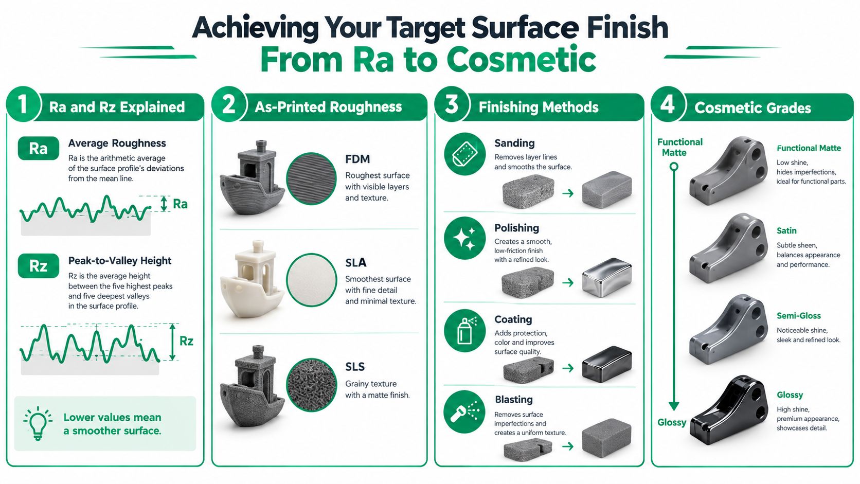
Achieving Your Target Surface Finish From Ra to Cosmetic
Surface finish specifications often confuse teams because visual appearance and measured roughness aren't the same thing. Ra describes average roughness across a measured length. Rz focuses on the height between prominent peaks and valleys. Two surfaces can look similar under normal lighting yet behave differently in sealing, sliding, bonding, or fatigue applications.
Start with the function. A cosmetic enclosure may need a uniform matte or glossy appearance, while a locating face may need controlled flatness and a defined roughness. A fluid-contact surface may require attention to valleys that can trap contamination. A fatigue-loaded metal component needs more than a pleasing appearance because surface defects can initiate cracks.
Choose the method by the defect
Sanding removes peaks mechanically and works well for accessible FDM and SLA surfaces. It also creates a risk: the operator can round edges, enlarge openings, or create a local low spot if pressure isn't controlled.
Bead blasting produces a more consistent matte texture across many polymer and metal surfaces. It's useful when the design accepts a uniform appearance, but masking and media selection matter around threads, holes, and thin walls.
Chemical or vapor smoothing can reduce visible layer texture by affecting the outer material. It may improve sealing or appearance, yet it can soften detail and alter dimensions. Use test coupons or a sacrificial part when the finished condition is not already validated.
Tumbling and vibratory finishing can treat multiple surfaces at once, which makes it attractive for repeatable batches. In a PLA study, vibratory finishing reduced as-printed surface roughness by 66%, and treatment duration was the dominant control variable for final surface quality, according to the study of vibratory finishing for PLA parts. The study also reported dimensional deviation after treatment, so more finishing isn't automatically better.
For service requirements, surface finishing options should be specified alongside the base material, critical dimensions, masking requirements, and inspection method.
Set a stopping point
A finish target should tell the operator when to stop. If the requirement is functional, measure the relevant face instead of polishing the entire part. If the requirement is cosmetic, define the viewing direction, texture consistency, color, gloss, and acceptable marks.
Finish only as far as the requirement demands. Every extra pass consumes time and can remove information, geometry, or edge definition.
Dimensional Accuracy Inspection and Material Constraints
Finishing changes geometry. Support removal can chip a corner, washing and curing can affect resin dimensions, blasting can soften edges, and sanding can move a surface below its drawing requirement. Inspection therefore belongs inside the workflow, not only at final shipment.
Use checkpoints that match the risk. Check support-sensitive datums after removal. Verify resin features after washing and curing. Measure a blasted or sanded interface after the surface treatment is complete. If machining follows printing, inspect the machined datum and record which process established the final dimension.
Match inspection to the question
A visual check is appropriate for color, coating coverage, obvious support marks, and general cosmetic consistency. Digital calipers can confirm accessible dimensions, but they may not provide enough control for complex profiles or tight interfaces. A CMM is better suited to datums, hole locations, planes, and profile relationships. CT inspection can reveal internal voids, trapped powder, blocked channels, or hidden defects when the geometry and application justify it.
Material behavior determines how aggressively you can finish:
- Resins can be brittle, especially around small support points, and they require complete cleaning and curing before functional evaluation.
- Nylons can retain powder in complex cavities and may need careful blasting or cleaning to avoid leaving contamination behind.
- Elastomers can deform under clamping or measurement force, so the inspection method must reflect their flexible condition.
- Metals can tolerate machining and abrasive operations, but heat history, residual stress, and surface condition remain central to performance.
Metal fatigue deserves special attention. An aerospace-focused review identifies rough as-built metal surfaces as a severe fatigue factor because surface irregularities can act as crack-initiation sites. The review also explains that surface post-processing can raise fatigue strength toward conventionally manufactured material levels by reducing roughness and, in some cases, introducing compressive residual stress, as discussed in this review of surface effects in metal additive manufacturing.
Before release, confirm that the team has:
- Verified critical dimensions after the last geometry-changing operation.
- Checked threads, holes, sealing faces, and assembly interfaces.
- Confirmed cleaning and curing records where the material requires them.
- Inspected cosmetic faces under the agreed lighting and viewing conditions.
- Recorded surface treatment, masking, coating, and repair status.
- Approved the part against the drawing, not only against a visual reference.
For metal additive design and production considerations, this metal 3D printing guide provides useful process context.
Designing to Reduce Post Processing Cost Time and Rework
A support mark on a sealing face can trigger sanding, inspection, dimensional correction, and another print. The better control point is the CAD review, before the build begins. Orientation, support placement, wall strategy, and feature geometry decide how much finishing work appears after printing, so post-processing belongs in the design decision rather than at the end of the route.
Start by identifying the surfaces that carry function or appearance: sealing faces, bearing seats, assembly datums, cosmetic areas, and inspection references. Orient the part so these surfaces either print cleanly or remain accessible to a predictable finishing tool. For example, changing orientation can reduce support contacts from 12 to 3, cutting removal work and lowering the chance of marks on a tolerance-sensitive face.
Prevention decisions for NPI
- Reduce support burden: Use self-supporting angles where the process allows. Split the part when a small assembly change costs less than extensive support cleanup.
- Protect thin details: Give fragile features enough local strength for cutters, files, blasting, and handling. A feature that breaks during removal can turn minutes of cleanup into a replacement build.
- Plan access: Leave routes for tools, media, cleaning fluid, and inspection probes. Internal cavities need a defined powder or resin removal method before the design is released.
- Separate finish zones: Apply a high-cosmetic requirement only to faces that customers or users will see. This prevents unnecessary finishing across the entire part.
- Reserve machining stock carefully: Where additive geometry transitions to CNC work, define stock and datums so machining has stable references and does not consume a critical feature.
Support removal and surface finishing can represent a large share of post-processing effort, as noted in the market overview above. Review those operations during design approval, because they can control both labor and scheduling even when the printed geometry appears simple.
In-house finishing provides quick feedback and direct access, but it requires trained operators, controlled equipment, safe material handling, and repeatable methods. Outsourcing may suit parts requiring specialized blasting, coating, dyeing, machining, inspection, or documented quality controls. Compare total cycle time, setup, transport, and rework exposure rather than judging the finishing line item alone.
FIRMFG combines SLA, SLS, FDM, and metal printing with CNC machining, vacuum casting, and surface finishing. An NPI team can coordinate support removal, sanding, polishing, dyeing, painting, vapor smoothing, or assembly through one manufacturing workflow. Its stated quality systems include ISO 9001 and ISO 13485, which may support projects requiring documented controls and traceability.
Design review question: Which finished surfaces must be created by the printer, and which can be produced more reliably by machining, coating, or a controlled finishing process?
Putting Post Processing to Work for Production Ready Parts
Production-ready post-processing starts with a clear chain of responsibility. The designer identifies functional and cosmetic surfaces. The manufacturing engineer selects the print orientation, support strategy, and finishing route. The quality team defines where dimensions and appearance will be checked. The supplier then confirms the sequence, equipment, masking, material condition, and acceptance criteria before the pilot build.
A practical brief should include:
- Printing process and material.
- Support or powder removal requirements.
- Washing, curing, stress relief, or heat-treatment requirements.
- Surface finish targets by face, including Ra or Rz where measurement matters.
- Masked areas, threads, holes, datums, and assembly interfaces.
- Final inspection method and the dimensions that require records.
- Cosmetic standards, coating requirements, and acceptable repair limits.
- Pilot quantity, lead-time objective, and the next design-review date.
The central lesson is simple. Post-processing is part of the product definition. It controls how the printed geometry becomes a usable surface, a stable material condition, and a verified assembly component. When the team designs for the finishing route, it reduces avoidable labor, protects critical dimensions, and makes short-run production more predictable.
FIRMFG supports 3D-printed parts with process-specific finishing, including support removal, sanding, polishing, dyeing, painting, vapor smoothing, and assembly, alongside CNC machining, molding, casting, and inspection. Visit FIRMFG to discuss your material, finish requirements, inspection checkpoints, and NPI or low-volume production plan.