Laser Cutting Stainless Steel: Specs That Matter
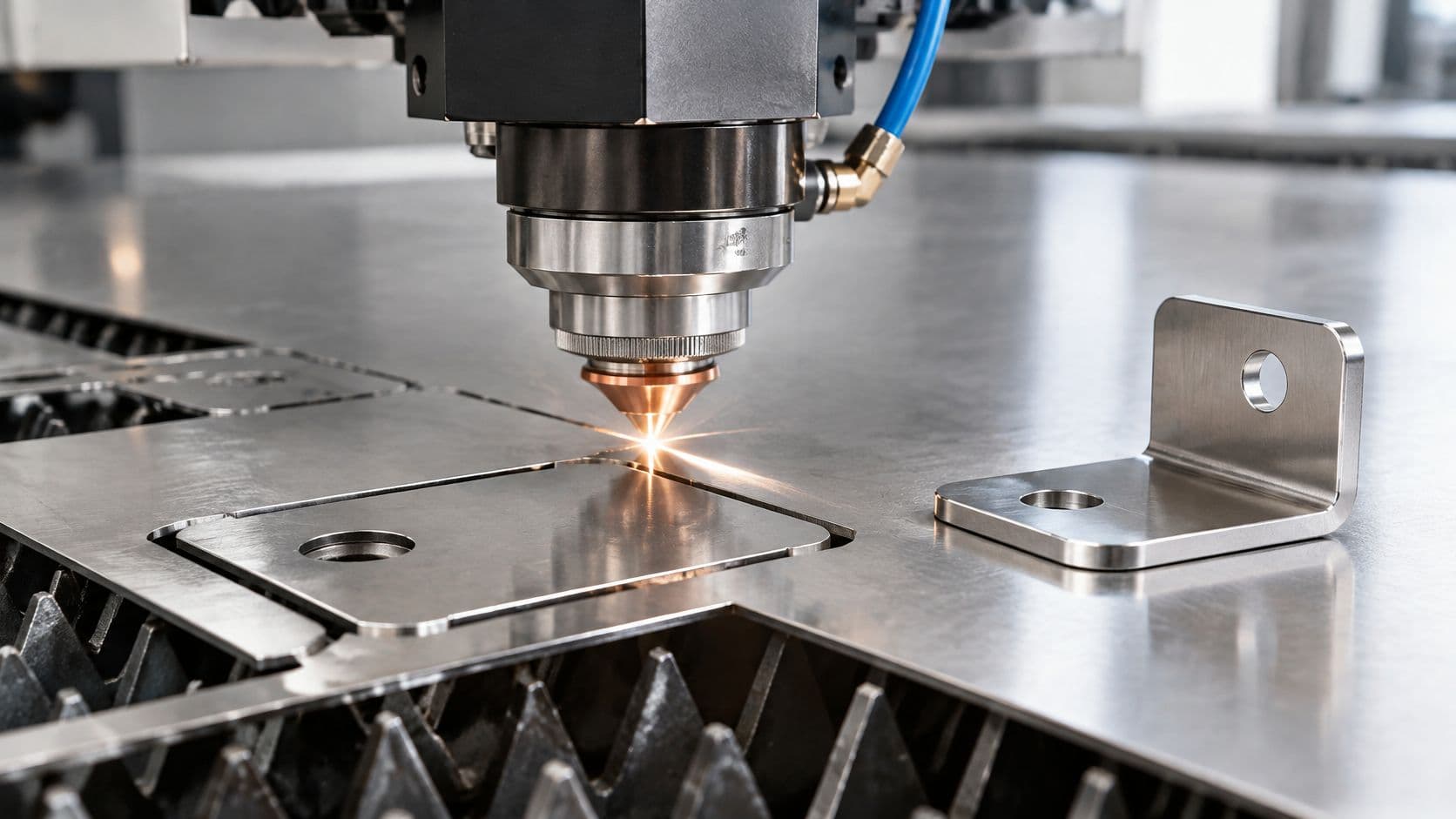
“Always use nitrogen” is incomplete advice for laser cutting stainless steel. Nitrogen is the right specification for an oxide-free edge, but the gas name alone won't control kerf, dross, or the heat-affected zone. Nozzle delivery, pressure, focus, and cutting speed determine whether the shop achieves that edge.
The purchasing decision is oxide-free edges versus throughput and total finishing cost, not nitrogen versus the cheapest gas. Specify what happens to the cut face next, then approve a process window that produces it. A hidden chassis bracket and a passivated weldment shouldn't carry the same cutting requirements.
Table of Contents
- Assist Gas Choices That Decide the Edge
Assist gas versus stainless edge intent
Air cutting needs a qualified nozzle
How a Laser Actually Cuts Stainless Steel- Shielding and ejection are separate jobs
Power Speed and Thickness Windows- What power, speed, and pressure did to stainless cuts
Edge Defects and What Changes Them- Stainless laser-cut defects and the first fix
Fume Risk and Compliance Controls- Audit the controls rather than the visible smoke
Prototype and Production Part Examples- Visible enclosure panel
Drawing and Quote Specs That Prevent Rework- Put acceptance criteria on the drawing
Assist Gas Choices That Decide the Edge
Nitrogen isn't automatic for every stainless part. It should be mandatory when your drawing requires a clean, oxide-free cut face for welding, passivation, or visible use without oxide removal. Compressed air can be reasonable for hidden components when the finishing route accepts its edge condition.
For painting, evaluate the complete preparation process. A coating doesn't make residual oxide or loose dross acceptable because it hides the metal.
Assist gas versus stainless edge intent
| Assist gas | Choose it when | Edge result | Main trade-off | Reference window |
|---|---|---|---|---|
| Nitrogen | Visible edge, weld, paint preparation, or passivation on austenitic stainless | Oxidation-limited face; suitable for demanding downstream preparation | Gas consumption and controlled purity | Tuned fiber-laser conditions described below |
| Oxygen | Throughput matters more than the color or condition of the raw edge | Reactive cutting can increase speed but leaves oxide and discoloration | Extra cleaning before demanding finishing or joining | Qualify on the actual alloy, thickness, and permitted oxide condition |
| Compressed air | Hidden brackets, internal enclosures, and parts with an approved cleanup operation | Acceptable when the drawing permits the resulting roughness and dross | Lower gas cost can be offset by cleanup and nozzle requirements | Optimized air-assisted fiber configuration described below |
In a controlled AISI 304 fiber-laser study, experiments covered 1,600–2,000 W and 8–14 bar, with a balanced condition near 2 m/min and 30% focus producing approximately 4.1 µm Ra and a 140 µm kerf. These are reference results, not a transferable machine recipe. A percentage focus setting is especially unsuitable for copying without knowing how the equipment defines it.
Oxygen supplies additional heat through an exothermic reaction. That can help throughput, but the buyer accepts an oxidized face and must account for its removal where the next operation requires clean metal.
Air cutting needs a qualified nozzle
An air-assisted process deserves evaluation on its measured output, not dismissal by gas name. In the study Enhanced Stainless Steel Cutting Quality Through Optimized Air-Assisted Fiber Laser Cutting with a Novel Supersonic Nozzle, experiments using a 3.3 kW fiber laser reduced AISI 304 kerf width from 284.97 µm to 228.12 µm, a 19.95% reduction, through the optimized nozzle configuration.
That result supports testing the delivery geometry. It doesn't establish equivalence to nitrogen for oxide-sensitive work.
Practical rule: Approve the gas, nozzle, and edge acceptance criteria together. A cheaper gas isn't cheaper if the operator has to grind every part.
Don't increase pressure by habit. Validate pressure with focus and nozzle stand-off, then select the matrix row that matches the finished edge rather than the machine's advertised capability.
How a Laser Actually Cuts Stainless Steel
A stainless cut succeeds when the beam melts a narrow path and the assist gas ejects the molten metal before it resolidifies. The beam establishes the kerf; gas delivery determines how reliably material clears through the thickness.
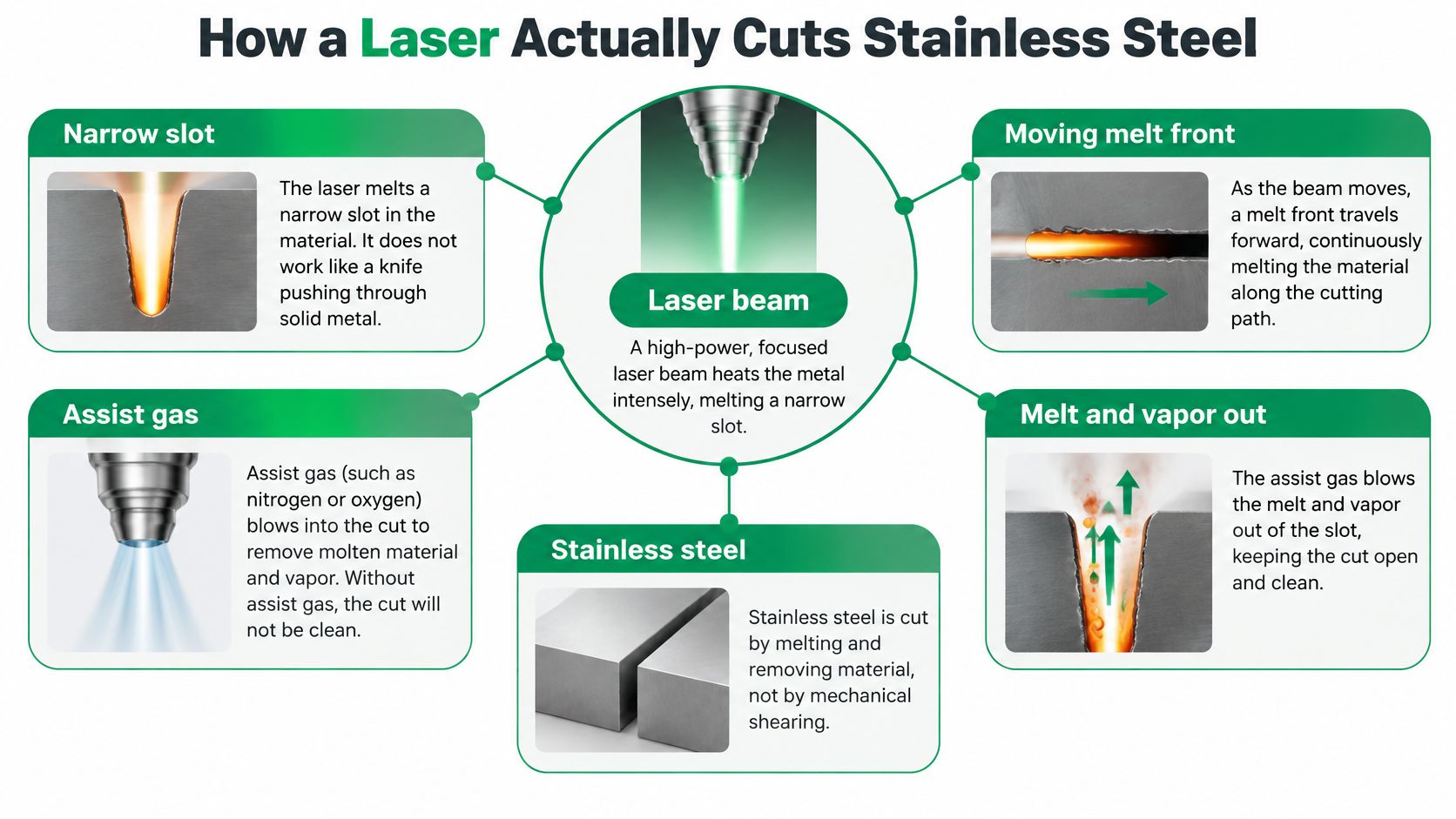
Shielding and ejection are separate jobs
In a 2020 Metals study of stainless-steel laser-cutting waste, researchers used dry nitrogen at 16 bar to limit oxidation in the cutting zone and eject molten and vaporized metal. The expelled particles retained chemical elements from the parent steel, and oxygen was still detected in particles after they left the cutting area.
A protected cut face does not mean every expelled particle remains isolated from the surrounding atmosphere. A bright edge also tells you little about the composition of collected dust.
Set the gas requirement on the drawing or process sheet. Specify nitrogen purity and dryness, then qualify the complete setup: nozzle delivery, pressure, focus, and cutting speed. Those variables work together to control kerf, dross, and heat-affected zone.
Translate the mechanism into a drawing
An enclosed profile can look correct from above while retaining attached material underneath. Include the exit side in inspection, not just the programmed outline.
Appearance, roughness, dimensional accuracy, and suitability for the next operation are separate acceptance criteria. Specify grade, thickness, allowable discoloration, and the next edge operation so the shop can match its process to the part's requirements.
Power Speed and Thickness Windows
A laser's rated power doesn't establish the quality of a stainless cut. The useful question is whether the source and settings can maintain penetration, geometry, and edge condition across your actual part.
A 2011 engineering comparison of fiber and CO2 cutting evaluated nitrogen-assisted cutting of 10 mm stainless steel using a 5 kW multimode fiber laser and a 4 kW CO2 laser; at matched cutting speeds, the fiber process required less calculated incident power. The finding supports better energy absorption under those conditions, not a blanket claim that rated kilowatts translate directly into cut quality.
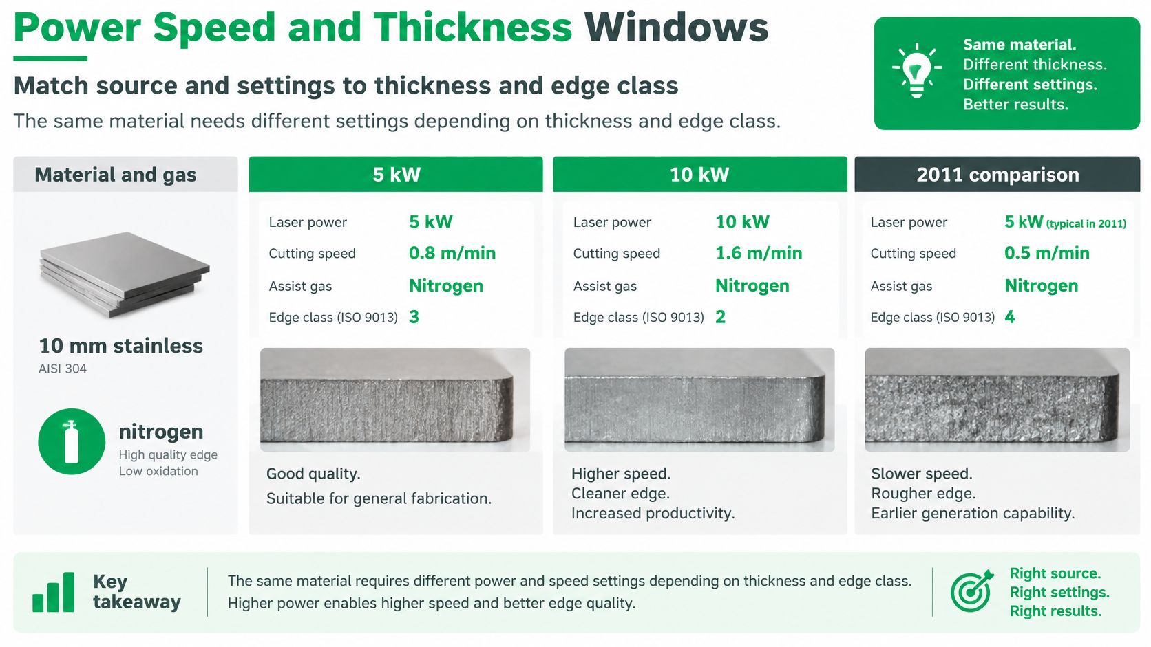
What power, speed, and pressure did to stainless cuts
| Change | Material and setup | What moved | Measured result |
|---|---|---|---|
| Fiber versus CO2 at matched speed | Nitrogen-assisted stainless plate in the comparison described above | Incident power needed | Fiber required less incident power |
| Increased cutting speed with power and pressure held | AISI 304 | Heat-affected zone | Narrower thermal footprint in the investigation discussed below |
| Increased speed in nitrogen-assisted optimization | Stainless cutting trials | Roughness and kerf | Lower roughness and narrower top and bottom kerf |
| Higher gas pressure | AISI 304 optimization | Kerf and taper | Kerf tended to widen; taper needs separate verification |
| Laser-power adjustment | Fiber cutting of SS201 | Top and bottom kerf width | Power strongly influenced kerf width in the study discussed under drawing specifications |
These findings describe directions to test, not a combined operating recipe. They come from different experimental conditions. Don't assemble settings from unrelated trials and treat the result as a qualified process.
Establish a usable window
Start with the correct material and thickness, using the machine's qualified starting parameters. Cut a coupon containing a straight edge, an internal contour, and a representative small feature. A simple square can miss problems caused by deceleration and concentrated heat around the actual geometry.
Then adjust deliberately:
- Hold the hardware constant. Inspect the nozzle and verify alignment before changing the thermal settings.
- Evaluate speed against penetration. Seek a clean exit edge, not merely the fastest head movement.
- Check geometry separately. Measure top and bottom dimensions when taper could affect fit.
- Retest the part's difficult region. A setting that works on a long straight line may fail in a dense hole pattern.
For procurement, machine time is only part of conversion cost. A fast cut that requires edge grinding, profile correction, or repeated inspection can be a poor production choice.
Thickness changes the job substantially. The beam must maintain a viable melt front and the gas must clear a deeper passage as material gets thicker. Don't transfer a sheet-metal recipe to plate merely because the alloy designation matches.
The approved window should include acceptable settings and observable failure boundaries. Record what happens when the process approaches incomplete penetration, excessive roughness, or unacceptable taper. That gives production a controlled adjustment range instead of a single unexplained preset.
Edge Defects and What Changes Them
Brown or blue discoloration is an oxidation warning, not merely a cosmetic nuisance. If the face must remain clean, check that the specified gas is reaching the cutting zone without contamination or an unintended substitution.
Before retuning, inspect the nozzle, protective optics, gas supply, and stand-off calibration. A damaged consumable can make a previously sound recipe look wrong.
Stainless laser-cut defects and the first fix
| What you see | Usual cause | First change |
|---|---|---|
| Brown or blue edge | Oxygen reached the hot metal | Restore the specified dry-nitrogen process when the edge must remain oxide-free |
| Bottom dross or beading | Melt wasn't fully cleared, because travel was too fast or delivery was unstable | Verify the jet, then slow slightly if penetration is marginal |
| Striations or missed cut-through | Insufficient effective energy along the cut path | Reduce speed and inspect the exit side on the actual thickness |
| Kerf wider than the qualified thin-sheet baseline | Excessive thermal input or unsuitable pressure | Test a pressure reduction after confirming nozzle condition |
| Heavy taper | Pressure and focal position aren't balanced | Reset focus against the qualified reference, then evaluate pressure |
| Wide heat tint or HAZ | Excessive heat input per unit length | Increase speed within the complete-penetration window |
A published kerf value isn't a defect threshold. Reject against the drawing or qualified process baseline, not against the narrowest result reported for another machine.
Use speed to manage heat without losing the cut
In an AISI 304 cutting investigation, increasing speed from 1.5 to 2.0 m/min reduced average HAZ width from 102 µm to 56.7 µm, approximately 44%. That demonstrates the potential effect of reducing energy delivered per unit length while holding the other relevant conditions constant.
It doesn't mean maximum speed is best. Beyond the workable window, the operator can lose penetration or leave rough striations and attached melt. Inspect both the face and underside after each adjustment.
Heat tint also isn't a direct measurement of HAZ width. If edge metallurgy matters to a bend, seal, or subsequent machining operation, agree on a sectioning or hardness-check method rather than estimating the affected region from color alone.
Troubleshooting discipline: Change one setting, cut the same feature, and record the result. Unlogged simultaneous adjustments make a successful coupon difficult to reproduce.
For residual burr removal, choose the tool according to edge access and permitted material removal. This guide to what a deburrer does helps distinguish cleanup from profile correction. Deburring shouldn't become an undocumented way to rescue an out-of-tolerance cut.
Fume Risk and Compliance Controls
A bright cut edge doesn't establish a clean breathing zone. Stainless contains chromium, and thermal processing can generate airborne particles and fumes that may include hexavalent chromium; the Journal of Materials Informatics review of relevant processing and emissions issues provides context for assessing these hazards.
Specify extraction independently from the assist gas. Changing the edge chemistry doesn't remove the need to assess worker exposure during cutting, table cleaning, filter maintenance, and dust handling.
Audit the controls rather than the visible smoke
- Identify the material. Provide the alloy documentation and expected workload to the person responsible for the exposure assessment.
- Capture at the source. Check table or enclosure extraction, including how capture is maintained across the active cutting area.
- Verify filtration. Require a documented filter arrangement, replacement procedure, and safe method for handling collected material.
- Check performance. Request airflow verification and relevant exposure-monitoring records rather than accepting fan capacity alone.
- Control secondary exposure. Include dust removal, suitable gloves and eye protection, and washing before eating in the written work practices.
Keep regulatory assumptions explicit
Cutting isn't welding, and an emissions estimate developed for another thermal process shouldn't automatically become a laser-cutting compliance calculation. Where published laser emission factors are limited, the assessor needs to document the chosen method and its applicability.
Ask the supplier to identify the local rules governing exposure, discharge, and collected waste. Require feasible engineering controls and appropriate work practices, with respiratory protection assessed where necessary rather than used as a substitute for effective source capture.
Maintenance deserves the same attention as operation. An enclosed machine can control emissions during cutting while an uncontrolled filter change exposes the person servicing it.
Prototype and Production Part Examples
A visible enclosure panel, an internal stiffener, and a precision flange may all start as stainless blanks. Their acceptance criteria should diverge before anyone nests them on a sheet.
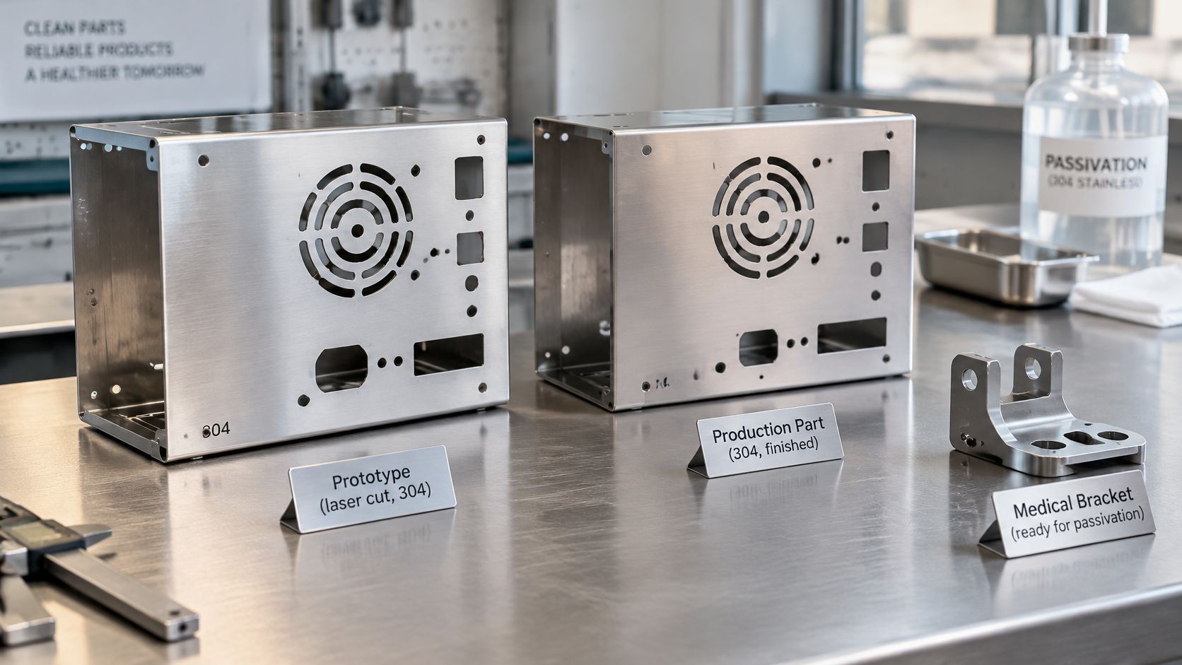
Visible enclosure panel
For a customer-facing panel, make the exposed edge part of the appearance specification. Specify nitrogen, an acceptable reference finish, and whether edge rounding is permitted.
Protect the show face during handling and agree on where any retention tabs may sit. A clean cut can still fail appearance inspection if tab removal leaves a witness mark on the visible perimeter.
For a part going to passivation, define the incoming surface condition with the finishing operation. Don't assume passivation will remove substantial cutting oxide or attached metal.
Hidden chassis bracket
An internal bracket can be a candidate for air cutting when the drawing accepts the raw edge and includes suitable cleanup. Approve a finished sample, not just an uncoated coupon.
The economic comparison should include:
- Cleanup effort. Account for dross removal and access around internal features.
- Coating preparation. Confirm that the surface presented to the coating process is acceptable.
- Assembly contact. Remove sharp or raised material where wiring, seals, or mating parts touch.
A hidden face isn't automatically an uncontrolled face. Burrs can interfere with assembly even when nobody sees them.
Flange with a precision interface
For a flange that will be welded, specify the joint-edge condition explicitly. Where it also has a sealing bore or closely controlled locating feature, reserve that feature for an appropriate finishing operation.
Kerf width and dimensional tolerance aren't the same thing. CAM compensation can account for a finite kerf, but taper, roughness, thermal effects, and repeatability still affect what the process can hold. Use machining or wire EDM where the functional requirement exceeds the demonstrated laser capability.
A complete stainless-steel fabrication workflow should identify the blanking, forming, joining, finishing, and inspection handoffs. Approve the prototype through those operations before releasing the pilot lot.
Freeze the successful process revision, but don't treat it as permanent. Requalify relevant changes in material, thickness, tooling, equipment condition, or edge requirements.
Drawing and Quote Specs That Prevent Rework
Write the edge intent before selecting kilowatts. In a 2025 Science and Technology Research Journal study of SS201 fiber-laser cutting, laser power accounted for 72% of bottom-kerf variation and 61% of top-kerf variation, while gas pressure accounted for 40.6% of kerf-taper variation. Those results reinforce why a gas-only purchase specification leaves important geometry uncontrolled.
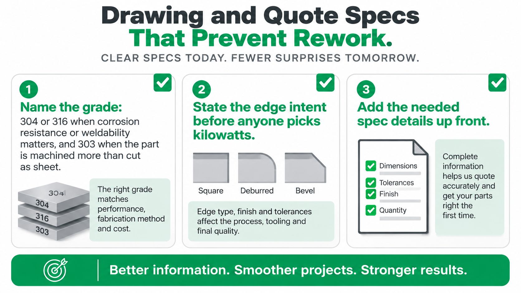
Put acceptance criteria on the drawing
- Name the grade and thickness. Don't substitute a machining grade for the required sheet alloy because it's available.
- Declare the edge class. Identify visible, hidden, welded, coated, and passivated faces. State whether oxide color is acceptable.
- Separate dimensions from finish. Put tolerances on functional features; call out roughness only where it affects performance.
- Flag difficult geometry. Identify narrow slots, dense hole patterns, small radii, and permitted retention-tab locations.
- Define first-article checks. Include complete penetration, underside condition, critical dimensions, and any required metallurgical verification.
Use the laser-cutting precision considerations to distinguish a profile that can be compensated in CAM from a feature that needs secondary finishing.
Send a quote-ready package
Send a STEP model or flat DXF, a controlled drawing, material and thickness, quantity, and the next operation. For an oxide-sensitive weldment, a useful edge note is: Nitrogen assist required. Cut edges shall be free of visible oxide discoloration and attached dross before welding.
We offer sheet metal laser cutting, bending, and surface treatment, alongside stainless CNC machining in grades 303, 304, and 316. Identify which features need each process so the quote includes the complete manufacturing route.
FIRMFG offers stainless-steel sheet metal fabrication with no minimums, including laser cutting, bending, and surface treatment. Visit FIRMFG with your drawing, grade, thickness, and edge requirements to request a quote that accounts for cutting and the operations that follow.