Plastic Injection Moulding Process: Step-by-Step Guide
Your prototype fits, the assembly works, and procurement wants a moulded-part quote. Then the questions arrive: Which resin grade? Where can the gate go? Is that deep pocket drafted? Why does a small change to the housing affect both tooling cost and production time?
The plastic injection moulding process is a connected chain, not a collection of independent settings. A material choice changes filling behaviour. Wall thickness changes packing and cooling. Those decisions determine whether the operator can eject a stable part or must keep adjusting the machine. Understanding that chain helps you make better decisions before anyone cuts the tool.
Table of Contents
Inside the Machine That Runs the Cycle- Clamp force must match the actual load
Mould Types and When Each One Fits- Match the tool to the production pattern
Choosing a Material for Moulding- Qualify recycled resin rather than rejecting it by default
Diagnosing Common Moulding Defects- Test the cause, not just the symptom
Design Rules That Keep Prototypes Moulding-Ready- Control the section geometry
What Drives Cost and Lead Time- Compare total cost at the forecast volume
Send Your Part Files for a Moulding Review- Make the review a decision checkpoint
The Five-Phase Cycle and Typical Timing
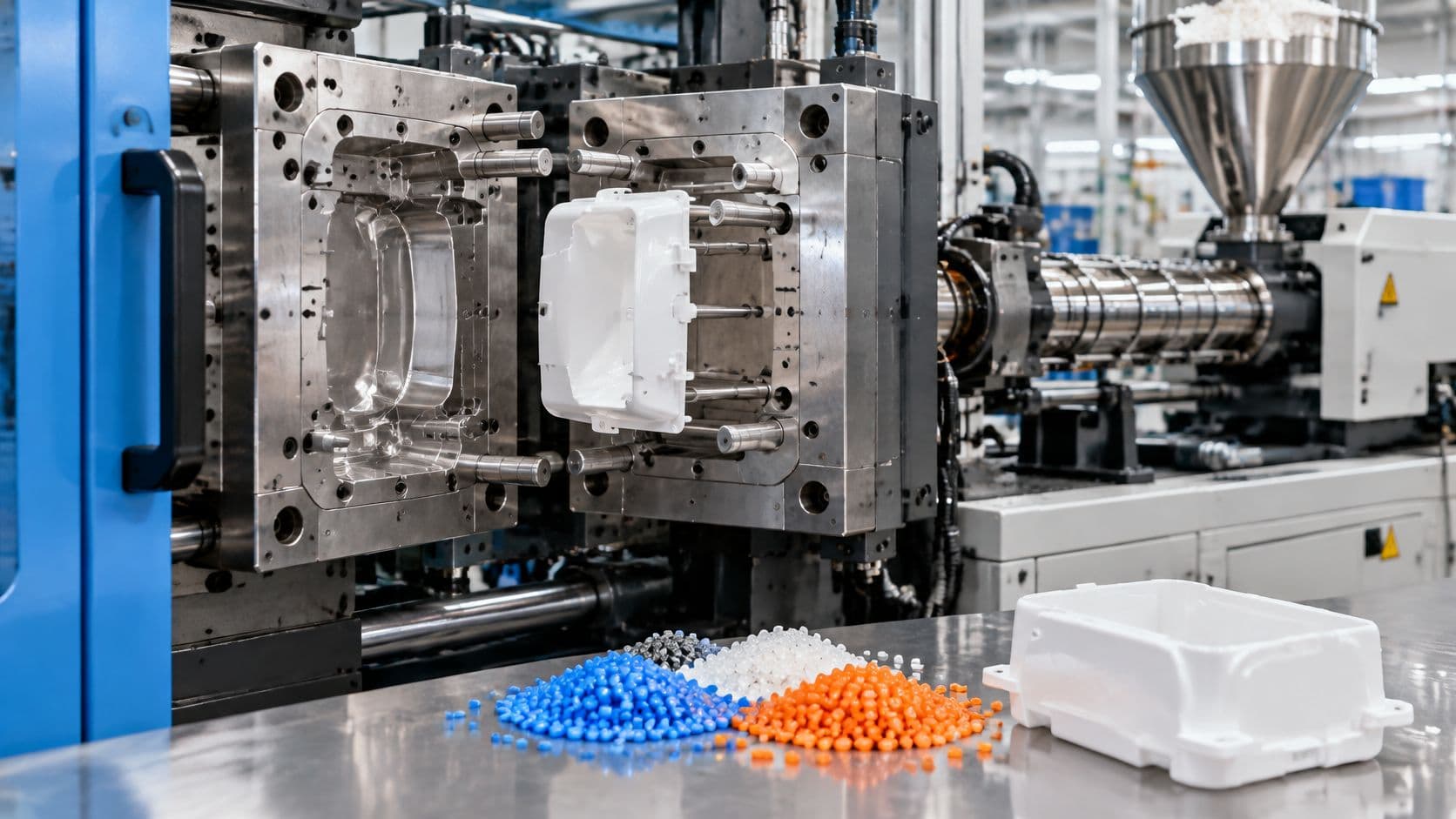
Think of a cookie press that melts its dough, forces it into a metal stamp, holds pressure to fill the gaps, waits for it to set, then pops the cookie out. Injection moulding follows that sequence, except the material is polymer melt and the stamp is a temperature-controlled mould.
Follow a small polypropylene housing through a shot. During plasticizing, the rotating screw conveys pellets along the heated barrel, melts them and meters enough material for the next injection. Once the mould is closed and clamped, the screw moves forward to fill the cavity.
The machine then switches from filling to packing and holding. Additional material compensates for contraction while the gate remains open. Cooling continues until the housing can withstand ejection without distorting.
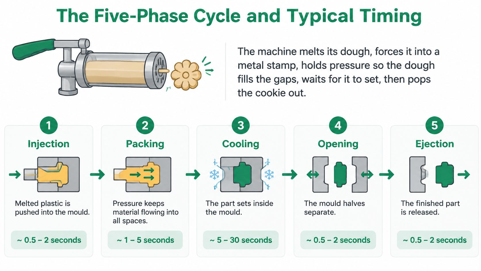
Injection moulding phases, timing and control variables
| Phase | What Happens | Typical Share of Cycle | Main Control Variable |
|---|---|---|---|
| Plasticizing | Screw rotates, melts pellets and meters the next shot | Runs in parallel with cooling when recovery finishes in time | Screw speed, back pressure, barrel temperature |
| Injection | Melt is pushed into the closed cavity | Fill interval before transfer to packing | Injection speed, switchover point to packing |
| Packing and holding | Extra melt compensates for shrinkage until the gate freezes | Continues while useful pressure can reach the cavity | Hold pressure, hold time |
| Cooling | Part solidifies inside the mould | Often the largest interval for conventional parts | Mould temperature, wall thickness, coolant flow |
| Ejection and reset | Pins push the part out and the mould closes again | Set by safe release and machine movement | Ejector layout, draft angle, mould motion speed |
Count elapsed time, not overlapping operations
The screw can prepare the next shot while the current part cools. Adding plasticizing time to cooling time would therefore overstate the cycle unless screw recovery extends beyond the available cooling interval.
A practical estimate combines fill, pack/hold, remaining cooling, and mould movement with ejection. Define those intervals carefully so cooling during holding isn't counted twice.
Don't shorten the cycle by ejecting a soft part. For a cooling-limited housing, reducing unnecessary material and improving heat removal can accomplish more than pushing the melt into the cavity faster.
Inside the Machine That Runs the Cycle
The machine must deliver a repeatable quantity of melt and keep the mould closed while that melt is under pressure. Its components serve those jobs.
The hopper supplies pellets to the barrel. Heater bands warm the barrel, while screw rotation also generates heat through mechanical work. The screw mixes and conveys material, then moves forward like a piston during injection.
At the front, the nozzle connects the injection unit to the mould's feed system. A poorly seated nozzle can leak; unsuitable temperature control can interrupt material flow. Neither problem is solved by increasing clamp tonnage.
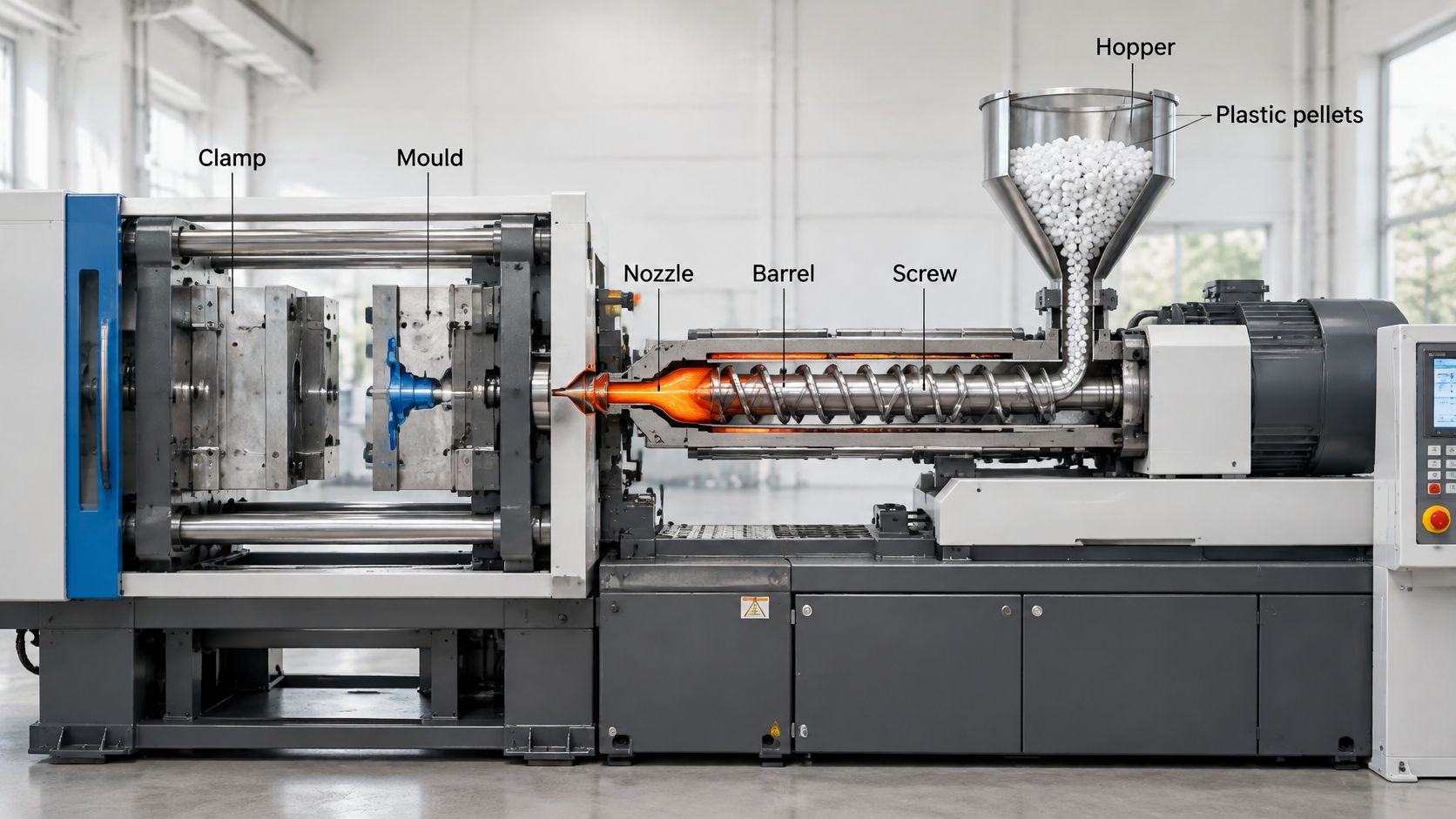
Clamp force must match the actual load
The clamp resists the separating force produced by cavity pressure acting over the projected moulded area. Comparing clamp force directly with injection pressure isn't enough: force and pressure are different quantities.
If the separating force exceeds the available clamping force, the mould can open slightly and produce flash. But excessive clamping isn't a universal cure. A damaged parting surface or unsuitable vent depth needs a tooling correction, not more force.
Architecture changes the energy comparison
A U.S. injection-moulding assessment held by MIT reported specific energy consumption of 19.0 MJ/kg for hydraulic machines, 13.2 MJ/kg for hybrid machines and 12.6 MJ/kg for all-electric machines, including auxiliaries, compounding and grid inefficiency.
That comparison supports considering machine architecture, but it isn't a prediction of your electricity bill. A production cell includes equipment beyond the press, and an energy figure with upstream losses isn't interchangeable with electricity measured at the machine.
Before selecting a press, check:
- Clamping capacity: Use the projected area of the complete shot and a justified cavity-pressure estimate.
- Injection capacity: Confirm the shot suits the screw, barrel and resin rather than merely fitting below maximum capacity.
- Physical fit: Check tie-bar spacing, mould height, opening stroke and ejection travel.
- Measurement boundary: Establish whether quoted energy includes drying, cooling and other auxiliaries.
Practical rule: Choose a machine around the mould and process window, not around the largest tonnage available.
An oversized press can still be a poor match for a small, heat-sensitive shot. Capacity alone doesn't establish process capability.
Mould Types and When Each One Fits
The cavity forms the part's outside, while the core forms its internal surfaces. Runners carry melt from the nozzle, gates control how it enters each cavity, and ejector pins release the solidified part. Cooling channels remove heat, so their layout affects cycle time and the risk of uneven shrinkage.
Tool complexity should follow the production pattern. More cavities can increase output per shot, but they also demand a larger feed system, balanced filling and a machine with enough capacity. A mismatch in any of these areas can turn a faster theoretical cycle into inconsistent parts or added process adjustments.
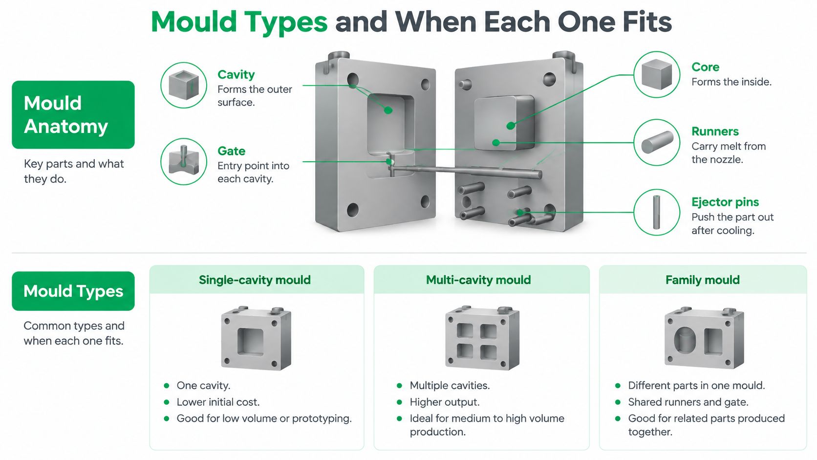
Mould types compared by structure, cavities, run size and relative durability
| Mould Type | Structure | Typical Cavities | Typical Run Size | Relative Tool Durability |
|---|---|---|---|---|
| Single-cavity steel (P20) | A single impression in prehardened tool steel | One part impression | Repeated production of one component | Generally high; wear depends on resin and maintenance |
| Family mould | Different components share one mould and shot | Separate impressions for the required components | Kits, assemblies and matched sets | Generally high with steel tooling; wear can vary across impressions |
| Aluminium prototype mould | Machined aluminium cavity and core | One impression or a limited cavity layout | Bridge builds and pilot runs | Generally lower than steel, especially with abrasive resins |
| Two-shot or overmould | Materials moulded sequentially using rotary or transfer arrangements | Layout matched to the sequential operations | Soft grips, seals and dual-colour parts | Depends on alignment and shut-off wear, as well as tool material |
Match the tool to the production pattern
A single-cavity steel tool suits sustained supply when demand does not justify a larger mould. Multi-cavity steel tooling can raise output when the forecast supports making identical parts together. The added cavities also require balanced filling; otherwise, parts may fill or cool unevenly, limiting the benefit of the higher output.
A family mould fits components used together. For example, a product may need a cap and matching lid. Making both in one tool can avoid separate moulds and runs, but it does not remove assembly. It can also be a poor fit when components need different quantities, materials or cooling conditions.
Aluminium tooling gives a team a way to make production-representative parts while design or demand remains uncertain. Its suitability depends on more than the metal: abrasive fillers, thin shut-offs and repeated modifications can shorten useful tool life or make the tool a poor fit, even for a modest programme.
Two-shot and overmould tools add material and alignment constraints. The materials and geometry must create the intended bond or mechanical retention, while substrate placement and shut-off control need attention in the quality plan. A weak match at this stage can lead to bonding or fit problems in the finished part.
Choose the simplest tool that meets the material, geometry and supply requirement. Add cavities when the forecast justifies them, not because a higher cavity count appears more production-ready.
Choosing a Material for Moulding
Start with the component's job. What load does it carry, what chemicals and temperatures will it encounter, and which surfaces must remain attractive? A flexible latch and a clear protective cover shouldn't begin with the same material shortlist.
Also separate material family from specific resin grade. Fillers, impact modifiers, colourants and recycled content can change processing and performance. Tool dimensions must reflect the selected grade's shrinkage behaviour, not a generic polymer label.
| Material | Type | Dry Before Moulding | Typical Uses |
|---|---|---|---|
| PP (polypropylene) | Semi-crystalline, flexible | Usually no, unless surface moisture or grade instructions require it | Living hinges, housings, containers |
| ABS | Amorphous, tough, good surface finish | Yes, using grade-specific drying conditions | Consumer enclosures, cosmetic parts |
| PC (polycarbonate) | Amorphous, impact resistant | Yes, with controlled moisture removal | Clear covers, medical housings |
| PA (nylon) | Semi-crystalline, tough, moisture sensitive | Yes, thorough drying required | Gears, clips, wear parts |
| POM (acetal) | Semi-crystalline, low friction | Usually no when correctly stored | Gears, bearings, sliding parts |
| PE (polyethylene) | Semi-crystalline, chemical resistant | Usually no when free from surface moisture | Containers, caps, chemical tanks |
For an enclosure, the choice often turns on stiffness, appearance, flexibility and chemical exposure. The ABS versus PP comparison helps narrow that decision, but grade approval should still follow the actual service requirements.
Qualify recycled resin rather than rejecting it by default
A polypropylene recyclate study published by Wiley found that increasing recyclate content improved tensile strength and elastic modulus while producing no significant viscosity change. That's a finding about the studied material stream, not a guarantee for every recycled grade.
The useful response is a qualification record:
- Material identity: Supplier, batch, grade, recycled content and colour.
- Incoming condition: Melt-flow information, moisture and contamination checks.
- Processing window: Drying conditions, melt and mould temperatures, injection settings and packing profile.
- Part acceptance: Dimensions, warpage, shrinkage, appearance and functional tests.
Clean runner regrind from the same polymer and colour is a better candidate for controlled reuse than mixed or heat-degraded scrap. It still needs an approved use limit and traceability, particularly where customer or application requirements restrict reprocessed material.
Approve the resin stream and its measured variation, not just the nominal datasheet.
Diagnosing Common Moulding Defects
Run initial shots, inspect fill and appearance, and measure the drawing's critical features before releasing a batch. Formal first-article acceptance should use parts from a stable process, with the measurement conditioning defined for the resin.
Work backward from the symptom to the earliest plausible cause. A visible defect isn't proof that the last operation caused it, and changing several settings together makes diagnosis harder.
| Symptom | Likely Cause | First Fix |
|---|---|---|
| Short shot, part not filled | Low melt temperature, inadequate injection pressure or trapped air | Check fill pattern and pressure limit; adjust temperature or speed, and clean vents |
| Flash, thin excess at parting line | Excess cavity pressure, insufficient clamp force or worn parting line | Verify clamp setup and pressure profile; inspect and repair mould edges |
| Sink marks | Thick section contracts after the surface sets | Check packing effectiveness and gate freeze; redesign excessive thickness |
| Warpage | Uneven cooling or unequal shrinkage | Check coolant circuits and mould temperatures; review wall transitions |
| Weld lines | Flow fronts meet without adequate fusion | Adjust melt or mould temperature within grade limits; review gate position |
| Burn marks | Trapped gas overheats near the end of fill | Clean or add appropriate vents; reduce end-of-fill speed |
| Splay or silver streaks | Moisture, volatiles or material degradation | Verify drying and material condition before changing fill settings |
Test the cause, not just the symptom
Use a short-shot study to examine the filling sequence. Check part-weight response when adjusting hold time to identify whether additional holding still feeds material through the gate. Compare actual mould-surface temperatures rather than relying only on controller setpoints.
Change a single variable, record the result, and keep the original setting available for comparison.
Longer hold time won't correct sink if the gate has already frozen. Likewise, hotter material won't solve trapped gas in a cavity with blocked vents. Respect the resin's processing limits while testing each hypothesis.
Reject prevention also matters beyond piece price. The U.S. Life Cycle Inventory injection-moulding dataset reports approximately 0.045 kg of rigid plastic scrap per kilogram of injection-moulded parts.
Keep reclaimable runners separate from contaminated waste. Record start-up scrap and rejected parts independently so the team can distinguish a difficult setup from an unstable production process. A short nominal cycle isn't useful if the operator must keep sorting defective parts.
Design Rules That Keep Prototypes Moulding-Ready
A machined or printed prototype can prove function without proving mouldability. Before freezing the design, examine how melt reaches each feature, how heat leaves it and how the finished component comes off the core.
Control the section geometry
Keep walls consistent. Use gradual transitions where thickness must change, and core out bulky bosses instead of leaving solid masses. This gives the process engineer a more manageable packing and cooling problem.
Make ribs thinner than their supporting walls. Build stiffness through rib depth and placement rather than a heavy rib base. Check the cosmetic face opposite each rib and boss during the design review.
Blend internal corners. Radii help the melt negotiate changes in direction and reduce sharp stress concentrations. Keep the outside geometry coordinated so adding a radius doesn't create an unintended thick section.
- Draft release surfaces: Add taper in the direction of draw, with extra attention to deep faces and textured surfaces.
- Locate gates deliberately: Prefer a feed position that supports effective packing and leaves a gate vestige in an acceptable location.
- Support ejection: Provide suitable contact areas rather than forcing ejector pins onto fragile or highly cosmetic features.
The design-for-manufacture guide for injection moulding provides a useful basis for checking these features before tool design. Record agreed exceptions on the drawing so they don't disappear during revision.
Remove complexity where it doesn't serve function
Undercuts may require slides, lifters or other release arrangements. Some geometries can strip from a core, but that requires suitable material flexibility and strain control; it isn't permission to ignore the undercut.
Say a snap-fit hook sits behind a side wall. Moving its release geometry to the parting line may allow a straight-pull tool while preserving the latch function. Confirm the opening direction and shut-off geometry before treating the change as complete.
Design judgement: Spend tolerance and tooling complexity on the features that determine fit, sealing or function.
For bridge production, avoid specifying production-tool sophistication by habit. Let the expected supply requirement and acceptable design risk determine the tooling approach. A prototype drawing should identify critical mating dimensions without imposing the same tight tolerance on every surface.
What Drives Cost and Lead Time
The lowest piece price isn't necessarily the lowest programme cost. A quote can look attractive because it excludes tooling changes, finishing, inspection or the scrap allowance needed to deliver acceptable parts.
Separate tooling investment from recurring production cost. Tooling reflects cavity count, mould size, material, surface finish and moving mechanisms. Piece price reflects resin consumption, machine occupancy, yield, handling and secondary operations.
Compare total cost at the forecast volume
A more expensive steel tool can be economical when its durability or cavity arrangement lowers recurring cost enough to recover the additional investment. A simpler tool can be the better choice when demand is uncertain or the design is still changing.
Use the same assumptions in each comparison:
- Accepted quantity: Compare delivered conforming parts, not just machine output.
- Included operations: Align trimming, inserts, assembly, finishing and inspection.
- Tool responsibility: Define ownership, maintenance, replacement and change charges.
- Production assumptions: State material grade, batch size and the proposed cycle basis.
The injection moulding cost guide helps organise that comparison. Ask for the assumptions behind the quote rather than negotiating only the final unit price.
Energy and scheduling need separate scrutiny
In an automotive car-fender moulding example discussed in a published injection-moulding energy study, plasticization accounted for 48% of measured energy consumption and barrel heating for 19%. That distribution makes a practical point: filling the cavity is only part of the energy demand.
Review screw recovery, idle operation and auxiliary equipment alongside the moulding settings. Don't apply an equipment-efficiency claim to a part quote without checking the operating conditions and measurement boundary.
Lead time follows a different chain: design approval, tool design, material and component procurement, machining, tool assembly, trials, corrections and part approval. A late resin change can affect shrinkage assumptions; a late texture decision can affect release requirements.
Settle those decisions before authorising irreversible work. Put dimensional acceptance criteria, cosmetic standards and approval responsibilities into the schedule. A tool isn't production-ready merely because its machining is finished.
Send Your Part Files for a Moulding Review
Prepare a quote package that lets an engineer evaluate the whole process rather than guess at missing requirements. Include the functional constraints as well as the geometry.
- Part definition: Send the native or neutral-format CAD model and a drawing with critical dimensions, tolerances and revision identification.
- Material requirement: State the approved grade, or describe loads, temperature, chemical exposure and appearance needs.
- Demand forecast: Provide expected batch quantities, annual demand and any anticipated design changes.
- Cosmetic requirements: Mark visible surfaces, texture, colour and acceptable gate or ejector locations.
- Downstream work: Identify inserts, assembly, finishing and inspection documentation.
Make the review a decision checkpoint
At FIRMFG, our NPI process follows five steps: design review, process design, tooling, pilot run and production. The sequence separates checking the design from establishing the process, building the tool and approving parts for manufacture.
Our design review examines CAD files for manufacturability. Before tooling approval, the team should resolve open questions about draw direction, release, material selection and acceptance criteria. Pilot parts then provide a checkpoint for checking the manufactured result, rather than assuming the digital model guarantees performance.
We offer injection moulding from prototype to production, including low-volume production with rapid tooling and batch manufacturing. That makes the expected build sequence relevant to the initial review, not something to decide after the quote.
This week, send the CAD file, material requirement and forecast volume together. Include the drawing revision and mark any requirements that remain open, so the review can identify tooling risks before the quotation is finalised.
FIRMFG offers plastic injection moulding with 100+ materials and no minimum order, including rapid tooling for low-volume builds. Visit FIRMFG with your CAD files, critical dimensions and expected quantities to request a moulding review before committing to the tool.