DFM for Injection Molding: A Practical Engineering Guide

The mold is on the press, the first shots are out of spec, and the defect can be traced to a geometry decision that was finalized in CAD weeks ago. A rib is too thick, a boss sits directly against the cosmetic wall, and the selected gate forces a weld line through a load-bearing area. At this stage, the design change may be simple, but the steel, sampling schedule, and launch plan are no longer simple.
DFM for injection molding exists to move those decisions upstream, while the part is still digital. It evaluates how geometry, material, mold construction, and process conditions interact, then connects those technical choices to the commercial questions that matter: startup scrap, dimensional approval, tool life, cavity-to-cavity consistency, and the number of iterations required before production can begin.
Table of Contents
Core Design Rules Every Part Needs- Start with mass distribution
Material Selection, Shrinkage, and Tolerance Strategy
Common Defects and How Design Prevents Them- Flash
Rapid Tooling and Low-Volume Workflow Options
A Practical DFM Review Checklist- Walls and transitions
How a Manufacturing Partner Supports NPI- A controlled NPI loop
What DFM for Injection Molding Actually Solves
DFM is a pre-tooling engineering practice. It reviews a molded part's geometry, wall thickness, ribs, radii, draft, gates, and cooling before the mold is cut. The purpose isn't to prove that plastic can enter a cavity. The purpose is to make the part fill, cool, eject, and remain dimensionally stable in a repeatable manufacturing system. The injection molding DFM guidance from Evok describes the same commercial logic, citing a 10× to 100× cost increase when a design flaw is corrected after tooling rather than during concept or design review.
The physics are straightforward, even when the consequences aren't. Molten resin flows through changing sections, transfers heat to the mold, shrinks as it solidifies, and experiences different restraint conditions across the part. A design that looks clean in CAD can still create uneven packing, trapped air, differential cooling, or excessive ejection force.
Practical rule: Treat DFM as a process-risk review, not a styling approval.
Four commercial outcomes to protect
A useful DFM review asks whether the design supports:
- Low startup scrap, by reducing predictable flash, sink marks, short shots, warpage, and weld-line problems.
- Fewer dimensional iterations, by addressing datums, shrinkage direction, gate influence, and cooling before the first tool trial.
- Stable tool life, by identifying abrasive materials, fragile shutoffs, difficult ejection, and features that will wear under production conditions.
- Cavity-to-cavity consistency, especially in multi-cavity tools, where runner balance, cooling balance, and tolerance strategy influence whether every cavity produces the same part.
Cooling deserves particular attention because it typically represents about 50% to 80% of the total injection molding cycle, according to the Evok injection molding DFM reference. Geometry that improves heat transfer and keeps mass uniform can affect lead time, scrap, and operating cost long after the CAD review is complete.
DFM differs from DFA, which focuses on how components fit together and how efficiently an assembly can be built. It also differs from a general engineering review, which may verify strength, appearance, interfaces, or performance without asking how the mold opens, where the resin flows, how air escapes, or how the tool will hold tolerance over its intended run.
The historical development of injection molding helps explain why this review has become essential. The process evolved from early candle and celluloid applications to screw injection machines and gas-assisted molding, as summarized in this history of injection molding. Modern part complexity and production scale make late geometry changes expensive. A short CAD review can prevent a long tooling problem.

Core Design Rules Every Part Needs
A mold quote can look reasonable until the first design review exposes a thick boss, a rib tied directly into a cosmetic wall, or a feature with no release path. Each geometry decision affects a recognizable failure mechanism, but these rules are a first pass, not a substitute for flow, cooling, or tolerance analysis. They also give buyers an early view of tool complexity, expected iteration count, and the risk of tolerance drift across multi-cavity runs.
Start with mass distribution
Keep the nominal wall as uniform as the part's function allows. A sudden transition from a thin wall to a thick boss or solid rib creates a local reservoir that cools more slowly than the surrounding material. That temperature difference can produce sink marks, internal voids, residual stress, and warpage.
For ribs, a practical manufacturer recommendation is to keep thickness at roughly 40% to 60% of the adjacent nominal wall thickness. Rib draft is often set around 0.5° to 1.5° per side, depending on material, texture, depth, and the release strategy. These are starting points for review, not universal limits. The guide to undercuts in injection molding also helps identify geometry that may force a different tool architecture. Use ribs to carry load through shape and orientation. Adding solid mass for stiffness often creates a cooling problem instead.
Bosses should usually be cored rather than made solid. Control the boss wall, add gussets where the load requires reinforcement, and separate the boss from a cosmetic outer wall when possible. That separation prevents the junction from becoming a thick, sink-prone island and reduces the chance of a cosmetic defect that triggers another sampling cycle.
Give the mold a clean release path
Draft lets the molded part release without scraping, scuffing, or distortion. A surface that appears vertical in CAD can grip the steel after shrinkage. Textured surfaces generally need more draft than polished surfaces because texture increases mechanical engagement.
Review draft separately on deep draws, ribs, bosses, and shutoff surfaces. If a feature must remain nearly vertical for functional reasons, document the constraint before steel is cut. The toolmaker can then evaluate lifters, sliders, ejection access, or a local redesign rather than discovering the problem during sampling.
Radii protect both the molded part and the mold. Sharp internal corners concentrate stress in the part and leave fragile tool steel at the matching cavity corner. Add a workable internal radius, then use the external radius to maintain the intended form and wall continuity. A radius can also improve resin flow around a corner, although its final size must still respect appearance and assembly requirements.
Control flow, air, and heat
Gate placement sets the filling pattern, weld-line position, packing behavior, vestige location, and available path for air to escape. A gate near a thicker section may improve packing there, yet leave a visible mark or move a weld line into a cosmetic zone. Choose the location against the part's functional, visual, and ejection priorities.
Vents need a practical path from the last-fill region to the outside of the mold. A blind pocket without adequate venting can trap air, burn resin, or cause a short shot. Cooling channels should be balanced across the cavity and core, with attention to thick bosses, deep pockets, and regions far from the main circuit. Beryllium copper inserts can remove heat from localized hot spots, but the design still requires review of material compatibility, wear, and maintenance.
| Feature | Rule of Thumb | Defect Prevented |
|---|---|---|
| Wall thickness | Keep sections as uniform as practical | Sink marks, voids, warpage |
| Draft | Taper all mold-opening surfaces | Drag marks, sticking, ejection damage |
| Internal radii | Avoid sharp internal corners | Stress concentration and tool damage |
| Ribs | Use a controlled fraction of nominal wall thickness | Sink marks and excessive cooling time |
| Bosses | Core out thick sections and support with controlled gussets | Sink marks, voids, distortion |
| Gates and vents | Place gates for balanced flow and vent last-fill areas | Weld lines, burns, short shots |
| Cooling | Balance heat removal across the tool | Warpage and dimensional drift |
Undercuts require an explicit decision because they change mold architecture. A side hole, snap feature, or recessed detail may require a lifter, slider, collapsible core, or redesign. During NPI, a rapid-tooling partner can test the release strategy and validate likely defect locations before committing to production steel. That early evidence can reduce late CAD changes, protect tool life, and clarify whether the selected geometry will hold its tolerance as cavities and production hours increase.
Material Selection, Shrinkage, and Tolerance Strategy
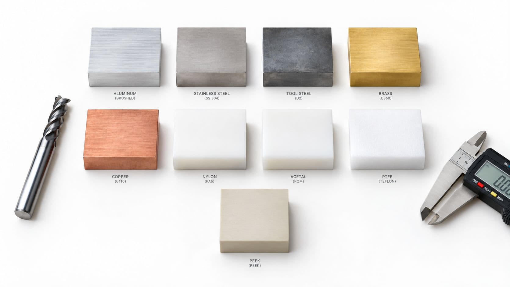
Material selection should begin with the part's job, then move immediately to molding behavior. ABS is a practical choice for general-purpose housings and balanced appearance. Polycarbonate suits applications that need impact performance and thermal capability. Polypropylene works well where chemical resistance, low density, or living-hinge behavior matters. Glass-filled nylon adds stiffness, but its directional shrinkage can distort flat parts and change the relationship between flow direction and critical dimensions.
The material's shrinkage behavior belongs in the mold design conversation, not only in the material specification. A cavity dimension is established with the expected molded-part dimension, resin behavior, cooling conditions, and orientation in mind. For glass-filled materials, the team also needs to consider anisotropy, because shrinkage can differ along and across the flow direction.
Design review question: Which dimensions must remain stable if the gate location or flow direction changes?
Critical dimensions need a tolerance strategy that matches the tool and process. Don't copy a tight tolerance from a machined-part drawing and assume molding will reproduce it automatically. Define functional datums first, identify which dimensions control assembly, and separate those from cosmetic or noncritical features.
The FIRMFG thermoplastics reference is useful when narrowing resin choices around performance and processing requirements. The final selection should also account for filler, color, recycled content, regulatory requirements, surface finish, and qualification burden. Material substitution isn't a neutral change. A new grade can alter flow, shrinkage, warpage, cooling, and the evidence needed for approval.
| Resin | Shrinkage (%) | Aluminum Tool Tolerance | Steel Tool Tolerance |
|---|---|---|---|
| Unfilled PC | 0.2 | Not specified in verified data | Not specified in verified data |
| Semi-crystalline resins | 0.4 to 0.7 | Not specified in verified data | Not specified in verified data |
| Glass-filled PA | Up to 1.0 | Not specified in verified data | Not specified in verified data |
The verified material guidance provides shrinkage ranges for resin families, but it doesn't establish universal tolerance values for aluminum or steel tools. Those values depend on geometry, tool construction, process control, measurement method, and cavity count, so a responsible DFM review should request the supplier's achievable tolerance statement for the actual feature.
Tooling strategy also affects qualification risk. Ask how the tool will be sampled, how cavity balance will be verified, which dimensions will be measured by CMM, and how tolerance drift will be monitored during the intended run. A tolerance that the commercial process can't support is not a demanding specification. It's a design problem that should be solved at the datum or interface.
Common Defects and How Design Prevents Them
A mold can run within its nominal process window and still produce defects if the geometry forces uneven filling, packing, cooling, or ejection. Review each visible symptom against its likely mechanism before changing machine settings. A small CAD revision often costs less than another sampling cycle after steel is cut.
Flash
Flash is excess resin at a parting line, shutoff, ejector interface, or another mold boundary. Thin shutoffs, poor parting-line geometry, excessive packing pressure, and inadequate support increase the risk. Put the parting line on a controlled edge, provide enough sealing land for the toolmaker, and avoid a filling strategy that requires unnecessary pressure. These choices also protect shutoff wear and help maintain dimensions across repeated runs.
Sink marks
Sink marks appear when a thick section cools and shrinks while the surrounding surface has already stabilized. The common causes are oversized ribs, bosses, and wall junctions. Core out the feature, reduce its effective wall thickness, and use a gradual transition. Add a gusset for stiffness instead of carrying solid mass into the outer wall. This reduces cosmetic rework and gives the tool a more predictable cooling load.
Warpage
Warpage results from differential shrinkage and uneven heat removal. Long flat covers, asymmetric walls, and glass-filled materials require particular attention because fiber orientation and cooling can pull the part in different directions. Balance the section, place ribs symmetrically where the function allows, and review cooling near heavy or isolated features. Correcting a cooling imbalance with cosmetic geometry usually shifts the problem rather than removing it.
Weld lines
Weld lines form when separate flow fronts meet. A line may be acceptable on a hidden surface, yet fail a cosmetic requirement or weaken a structural load path. Relocate the gate, change the flow path, add a flow leader, or move the feature that splits the front. With reinforced resin, weld-line placement is a mechanical design decision because fiber orientation at the meeting point can affect local strength.
Short shots
A short shot is an incomplete fill. Thin restrictive sections, poor venting, an unfavorable gate location, and an excessively long flow path can cause the resin to freeze before the cavity is full. Raising pressure may mask the problem temporarily while increasing flash, molded-in stress, or tool loading. Correct the flow path first, then verify gate size, venting, material choice, and the available process window.
The Evok source on injection molding DFM groups flash, sink marks, short shots, warpage, and weld lines among the dominant quality risks and describes them collectively as 91% of injection molding quality issues. The commercial impact is straightforward. Each defect can add sampling, sorting, tooling correction, or engineering time after the mold exists. Geometry changes remain cheaper before production steel is committed, and they reduce the iteration burden during NPI.
| Defect | Root Cause in Design | Preventive Design Change |
|---|---|---|
| Flash | Difficult shutoff or pressure concentrated at the parting line | Improve parting-line geometry and reduce unnecessary pressure demand |
| Sink marks | Thick ribs, bosses, or wall junctions | Core out mass and keep reinforcing features within the wall-thickness rule |
| Warpage | Uneven mass, cooling, or directional shrinkage | Balance geometry and review material orientation and cooling |
| Weld lines | Flow fronts meeting in a critical area | Relocate the gate or move the meeting line away from stress and cosmetic zones |
| Short shots | Long restrictive flow path or trapped air | Improve flow continuity and vent the last-fill regions |
During tool review, connect these changes to the buyer's real risks: tool life, tolerance drift between cavities, and the number of design iterations before release. A rapid-tooling partner can expose filling, venting, cosmetic, and assembly problems with representative molded parts before the team commits to a production-steel architecture. That evidence helps separate a geometry issue from a process-setting issue and supports a more defensible NPI decision.
Rapid Tooling and Low-Volume Workflow Options
Tooling should be selected against the learning required, not only the nominal production forecast. A prototype tool may answer form and fit questions, while a bridge tool may expose cosmetic and assembly risks. Production steel becomes appropriate when the geometry, material, quality requirements, and volume justify long-run durability.
The FIRMFG rapid tooling service overview describes rapid tooling as part of an iterative path from design validation to low-volume molding. That path is valuable when the team needs representative molded parts before committing to the final tool architecture.
| Tooling Type | Lead Time | Shot Life | Best-Fit Volume |
|---|---|---|---|
| Rapid tooling | Shorter than production tooling, project dependent | Project dependent | Early design validation and low-volume builds |
| Aluminum tooling | Often selected for fast, lower-volume work | Limited relative to production steel | Design validation and short runs |
| Bridge tooling | Between prototype and production strategy | Depends on material and construction | Low-volume production and cosmetic validation |
| Hardened steel | Longer build and qualification path | Selected for extended production use | Higher-volume programs and demanding durability |
Aluminum can be a sensible choice when the part geometry is still moving and the team needs molded evidence quickly. It isn't automatically the right option for abrasive resin, demanding cosmetic surfaces, or a run where maintenance interruptions would be costly. Bridge tooling can preserve more production-like features while avoiding an immediate commitment to the final multi-cavity architecture.
Hardened steel supports a longer production horizon, but it makes early design indecision expensive. The toolmaker must understand cavity count, expected shot demand, resin abrasiveness, surface finish, spare-component strategy, and the acceptable level of tolerance drift. Buyers should ask how many samples are included, what happens after a failed first trial, and whether the same cavity datum strategy will carry into the production tool.
A rapid tool should generate production knowledge, not just temporary parts.
The strongest workflow uses rapid or soft tooling to validate geometry, material behavior, cosmetic zones, gate vestige, ejection, and assembly. Once those decisions are frozen, the supplier can transfer the approved part geometry, critical dimensions, and lessons learned into production steel without re-cutting the entire design from scratch. The handoff still requires a new tool review, because cavity count, runner balance, cooling, and maintenance access may change.
A Practical DFM Review Checklist
A useful review follows the part feature by feature. The goal is a quote-ready drawing, or a clearly documented list of decisions that still affect cost, quality, or schedule. Review geometry together with tool-life risk, tolerance drift across cavities, and the number of likely design iterations.
Walls and transitions
- Nominal wall: Define the intended wall for the selected resin and identify every thick section.
- Uniformity: Compare transitions around ribs, bosses, snaps, and windows. Abrupt mass changes can drive sink, voids, and warpage.
- Core-out: Replace solid bosses and heavy pads with cored geometry where function allows. This reduces thermal mass and shortens cooling demands.
- Flow path: Check whether thin sections sit downstream of restrictive features or long unsupported runs. Mark areas where hesitation, weld lines, or short shots may occur.
Ribs, bosses, and ejection
- Rib proportion: Keep ribs near 40% to 60% of adjacent wall thickness as a starting point. Adjust for resin, appearance, loading, and the risk of sink at the rib-to-wall intersection.
- Rib root: Add a radius instead of a sharp intersection that concentrates stress and restricts flow.
- Boss support: Core the boss, separate it from cosmetic walls, and use thin gussets for load transfer. Check screw torque, insert installation, and ejection loads.
- Ejection surface: Place ejectors on hidden or noncosmetic areas. Confirm that the part will not deform under ejection force, especially around deep pockets and flexible clips.

Draft and parting lines
- Mold-opening direction: Establish it before finalizing clips, holes, lettering, and side features.
- Draft: Set taper for the finish, depth, texture, and ejection method. Polished and textured walls may require different draft decisions.
- Parting line: Put it on a functional edge or hidden boundary where possible. Confirm flash risk, shutoff condition, and whether the line will remain acceptable after tool maintenance.
- Undercuts: Decide whether each one should be eliminated, pulled with a side action, formed with a lifter, or handled with an insert. Compare added tool cost and wear with the value of retaining the feature.
Gates, vents, cooling, and specifications
- Gate location: Mark the gate vestige and confirm that the fill path avoids cosmetic and high-stress zones. Consider weld-line position and the effect of gate changes on later iterations.
- Vent locations: Identify last-fill areas, blind pockets, and potential air traps.
- Cooling: Check both mold halves, thick features, and areas likely to retain heat. Uneven cooling can create cavity-to-cavity dimensional drift during longer runs.
- Datums: Define functional datums that reflect assembly, not merely the easiest CAD reference.
- Tolerance stack: Separate critical dimensions from general dimensions and ask the supplier to confirm process capability by cavity.
- Cosmetics: Mark Class-A surfaces, texture requirements, gloss expectations, allowable witness marks, and gate or ejector restrictions.
Before the RFQ, provide the approved material grade, revision-controlled model, drawing with functional datums, cosmetic-zone map, volume band, target inspection method, and open DFM decisions. These inputs let the supplier price the intended product, plan sampling, and identify changes before production steel or a multi-cavity layout makes iteration expensive.
How a Manufacturing Partner Supports NPI
A manufacturing partner adds value during NPI by converting a CAD model into decisions that affect quality, cost, tool life, and schedule. Send a revision-controlled model with PMI or drawing data, the intended resin and grade, critical functional dimensions, cosmetic requirements, annual volume band, expected iteration path, and target unit-cost range.
The first supplier review should answer questions that standard DFM checklists often leave open:
- Analysis method: Which filling, cooling, and warpage analyses will be run, and which assumptions will be recorded?
- Engineering changes: How many DFM and ECN review rounds are included before tool release?
- Tool-life plan: Which steel or insert materials are proposed? How will wear affect shutoffs, slides, texture, and cavity dimensions?
- Sample validation: Will first-article results include CMM data, dimensional results by cavity, material traceability, and visual inspection records?
- Mid-build changes: Who approves a geometry change after machining starts, and what will it do to cost, schedule, and approved interfaces?
These questions connect geometry to commercial risk. A wall-thickness correction may be inexpensive in CAD, while a gate change after machining can affect runners, cooling, ejection, parting lines, and sampling. In a multi-cavity tool, cavity identification and cavity-by-cavity comparison are also required. An acceptable average can conceal one cavity with drift or a recurring defect.

A controlled NPI loop
A practical NPI sequence starts with design DFM feedback, then uses rapid tooling or aluminum soft tooling to observe how the actual resin fills, cools, ejects, and appears. Samples should test more than part approval. They should show whether gate location, texture, parting line, tolerance strategy, and assembly interfaces perform as intended.
A partner such as FIRMFG can support this work through rapid tooling, low-volume injection molding, CNC machining, additive prototyping, vacuum casting, and finishing. These options let a team compare process choices while geometry is still adjustable. The useful measure is whether each sample produces a controlled design or tooling decision, rather than just adding another prototype.
Once geometry is frozen, preserve the approved DFM findings in the production-tool package. The production review should then address cavity count, runner and cooling balance, tool-life assumptions, inspection plans, and tolerance drift across the run. Rapid tooling reduces NPI risk when it exposes filling, cooling, ejection, cosmetic, or assembly problems before production steel commits the design.
FIRMFG provides rapid tooling, low-volume injection molding, and DFM feedback for teams validating molded parts before production-tool commitment. Review your CAD model, resin, critical dimensions, and cosmetic requirements with the manufacturing team, then visit FIRMFG to request a project assessment and start the next iteration with manufacturability decisions in place.