Jigs & Fixtures: A Practical Engineering Guide
You've tightened the CNC program, checked the tool offsets, and still can't get the hole pattern to repeat. The first part passes inspection, the next one shifts, and a third part reveals a problem that wasn't visible on the machine screen. Before changing the machine tolerance again, look at the physical interface between the part and the process.
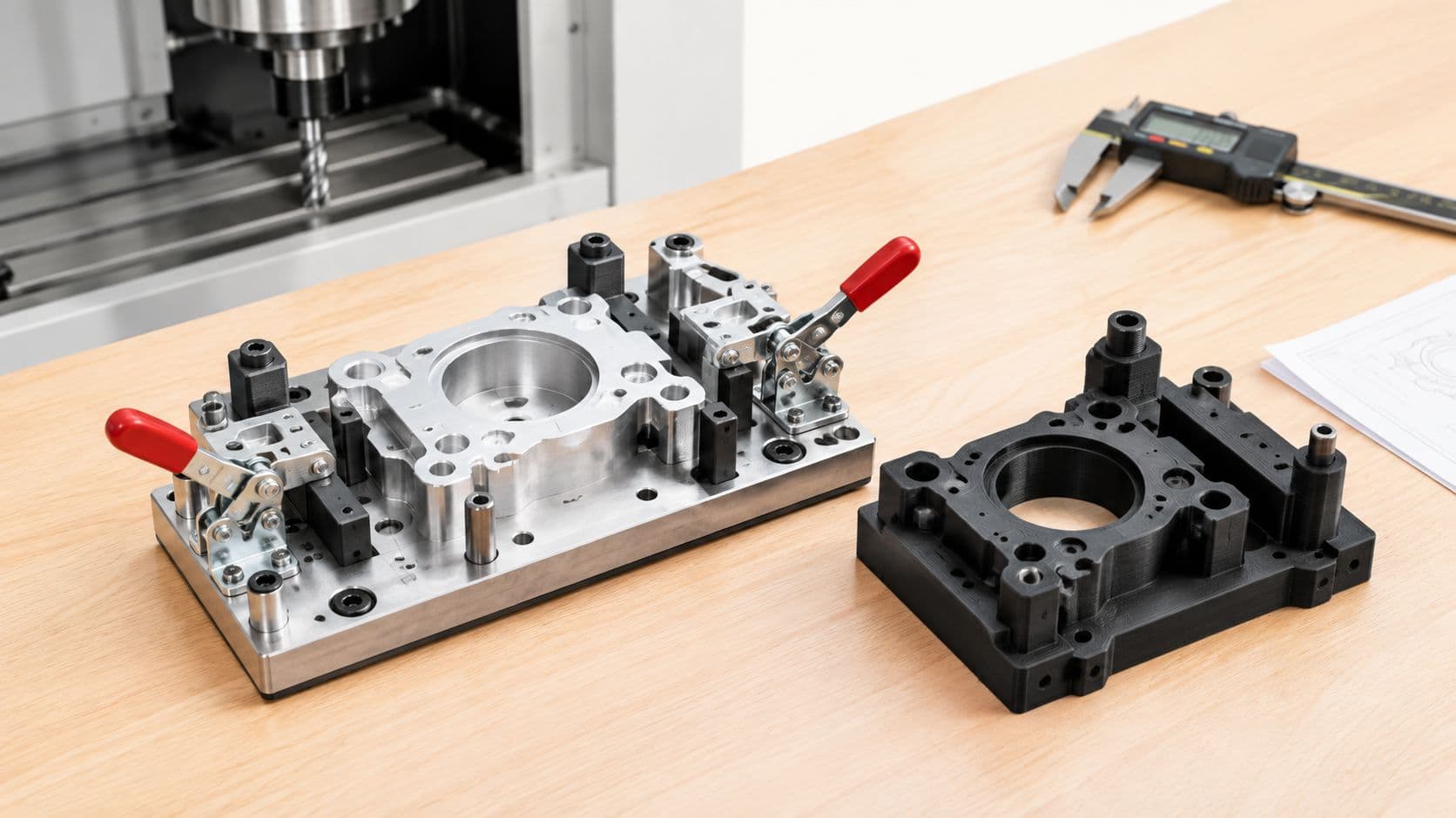
That interface is the jig or fixture. It determines where the workpiece sits, how cutting forces travel, whether the operator can load it consistently, and how much variation reaches the finished part. A sound workholding plan connects datums, tolerances, clamping, inspection, manufacturing method, and lifecycle cost. Rigidity matters, but rigidity alone doesn't guarantee repeatability.
Table of Contents
- Why Workholding Makes or Breaks Your Part
Put workholding on the drawing early
Treat repeatability as an error chain
What Jigs and Fixtures Actually Do- Four functions on the shop floor
The 3-2-1 Locating Principle- Locators constrain, clamps restrain
Dedicated Versus Flexible Fixtures- Use the run profile to choose
Materials and Manufacturing Methods Compared- Compare the process against the requirement
Inspection and Fixture Qualification- Measure the features that control the process
Cost, Lead Time, and Lifecycle Tradeoffs- Price the workholding over its life
Outsourcing to a Precision Prototyping Partner
Why Workholding Makes or Breaks Your Part
A part that won't repeat usually creates a tempting diagnosis. Engineers check the machine, replace a tool, adjust offsets, or tighten the drawing tolerance. Those actions can help, but they won't correct a locator that contacts a rough surface, a clamp that bends a thin wall, or a datum scheme that lets the part settle in more than one position.
Jigs and fixtures aren't accessories added after the design is complete. They're physical process-control systems. During the Industrial Revolution, their systematic development helped manufacturers move from craft production toward standardized, repeatable manufacturing by reducing dependence on highly skilled manual alignment. The same principle supports modern CNC machining, welding, sheet-metal fabrication, inspection, and assembly. Historical research on jigs and fixtures describes their continuing role in connecting geometry, datums, tolerances, and production repeatability.
Put workholding on the drawing early
Start with the part, not the fixture hardware. Identify the surfaces that are stable, functional, accessible, and sufficiently rigid to serve as locating datums. Then ask how the part will be loaded, clamped, machined, inspected, removed, and loaded again.
A practical review should answer these questions:
- What must be located: Which features control the finished part's function, and which surfaces can support that requirement?
- What must be supported: Where could cutting, welding, drilling, or clamping deform the workpiece?
- What must be accessible: Can the tool, probe, inspection device, and operator reach the required features?
- What must be repeatable: Is the critical requirement part-to-part location, tool guidance, orientation, or changeover?
- What may change: Will the fixture see one geometry, several variants, or repeated design iterations?
The answers define the workholding function before anyone chooses aluminum, steel, printed polymer, or a standard vise.
Practical rule: If the fixture strategy appears only after the first bad batch, the project has already paid for late design work through scrap, rework, or schedule delay.
Treat repeatability as an error chain
A fixture can match the CAD model and still produce inconsistent parts. Real accuracy depends on the complete localization-error chain, including locator-position variation, geometric error in locating elements, and variation in the workpiece's datum surfaces. Wear, chips, contamination, poor alignment, and insufficient rigidity all add error between the part and the cutting tool. Fixture tolerance research_2008_424-433.pdf) recommends evaluating the locating scheme through geometric, kinematic, force, and deformation analyses rather than treating nominal dimensions as proof of performance.
That changes the design question. Instead of asking, “How rigid can this fixture be?” ask, “Which physical features define the part position, how much can each vary, and how will inspection reveal the difference?”
What Jigs and Fixtures Actually Do
A jig holds and locates a workpiece while also guiding the cutting tool. A fixture secures, supports, and positions the workpiece, while the machine controls the tool path. A printed drilling template is a useful analogy for a jig because it tells the drill where to go. A vise is closer to basic workholding, while a purpose-built milling fixture adds controlled location, support, and repeatable loading.
The distinction matters because each device has different maintenance priorities. A jig may rely on guide bushings whose position and wear affect hole placement. A fixture depends more heavily on datum surfaces, locating pins, clamp repeatability, support condition, and resistance to vibration. Both can be precise, but they control different parts of the manufacturing process.
Four functions on the shop floor
Every workholding design performs some combination of four functions:
- Locating: Establishing the part's position relative to the machine, tool, robot, or inspection system.
- Supporting: Preventing bending, vibration, or local collapse under process loads.
- Clamping: Restraining the part against the locators without shifting or distorting it.
- Guiding: Controlling tool entry or travel, as a drill bushing does in a traditional jig.
A CNC milling fixture generally emphasizes locating, supporting, and clamping because the programmed machine controls tool motion. A drilling jig adds physical guidance when the tool needs a mechanical reference. Inspection fixtures use controlled orientation so measurements compare the part against the intended datum scheme rather than against an improvised setup.
Why the distinction still matters in modern manufacturing
The terms emerged from a broader manufacturing shift. Jigs and fixtures became foundational technologies during the 18th and 19th centuries, when defined reference surfaces allowed drilling, milling, inspection, and assembly operations to repeat across workstations and operators. Their underlying logic remains unchanged even as hardware has evolved.
Modern systems may use modular bases, quick-change elements, hydraulic or pneumatic clamping, sensor feedback, computer-aided design, or additive-manufactured workholding. These additions don't replace the core functions. They extend them to automated cells, low-volume production, rapid prototyping, and programs where the product geometry changes frequently.
For a junior designer, the safest vocabulary is simple. If the device guides the tool, think jig. If it positions and holds the work while the machine guides the tool, think fixture. Then verify the actual process, because hybrid tools can combine both roles.
The 3-2-1 Locating Principle
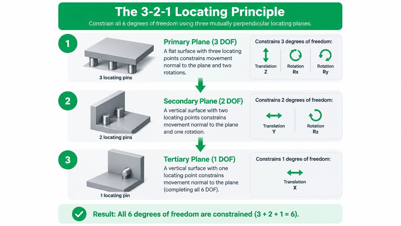
The 3-2-1 locating principle gives you a practical constraint model for a rigid workpiece. Three contacts establish the primary plane, two contacts establish a perpendicular secondary plane, and one contact establishes the tertiary direction. Together, these contacts remove the workpiece's six rigid-body degrees of freedom, three translations and three rotations. Technical guidance on fixtures describes this arrangement as the fundamental constraint model for precision workholding.
Start with the primary plane. Three points prevent the part from moving toward or away from that plane and control rotation about the two axes parallel to it. The secondary plane then removes sideways translation and rotation about the remaining relevant axis. The tertiary locator removes the final translation. The arrangement is simple because every contact has a specific job.
Locators constrain, clamps restrain
Clamps shouldn't locate the part. They should push it against the locating elements. If a clamp also determines position, its force, contact condition, and operator motion can shift the workpiece or distort a flexible region.
Place locating elements on reliable machined surfaces whenever possible. Space them as widely as the geometry allows, because wider spacing reduces sensitivity to angular error. Put supports and locators near rigid regions, but don't let them block cutting access, inspection access, chip evacuation, or safe loading.
Irregular parts may need V-blocks, pins, buttons, adjustable stops, or shaped nests. The 3-2-1 logic still applies. Each added contact should have a clear constraint function. If a contact duplicates an existing constraint without a reason, it may over-constrain the part.
The real accuracy chain
The textbook model assumes perfect contacts and a perfect workpiece. A real setup includes:
- Locator-position variation: A pin or stop may not be exactly where the drawing places it.
- Locator geometry error: Flatness, perpendicularity, roundness, and wear affect contact.
- Datum-surface variation: The workpiece may arrive with variation on the surfaces used for location.
- Contact condition: Chips, coolant, burrs, and contamination can create false seating.
- Load response: Clamping and cutting forces can move or deform the part.
Assign explicit tolerances to locator position, flatness, perpendicularity, and wear surfaces. Use worst-case analysis when you need a conservative maximum error, statistical analysis when variation can be modeled through distributions, and Monte Carlo simulation when several nonlinear or distributed errors interact. Evaluate the fixture tolerance against the part's functional datum scheme, not as an isolated tooling number.
Dedicated Versus Flexible Fixtures
A production forecast changes, a datum moves, or a second variant enters the line. The fixture decision made months earlier now affects location error, inspection work, changeover time, and capital cost. Dedicated and flexible fixtures are different lifecycle choices, not just high and low levels of quality.
A dedicated fixture is built around one part geometry. Choose it when the geometry is stable, the process is defined, and future variants are unlikely. Fixed locators, supports, and clamps can keep the error chain short because each contact has one intended position. That arrangement often improves repeatability, but a new hole, altered wall, or shifted datum may require rework or make the tool unusable.
A flexible fixture accommodates multiple geometries through modular, adjustable, or reconfigurable elements. It suits pilot builds, mixed-model production, related variants, and frequent engineering changes. The trade-off is measurable: every adjustable joint, interchangeable plate, and removable support adds another source of position variation. Verification must confirm each configured state, not just the base structure.
A systematic review of fixture investment and flexibility reports that jigs and fixtures may represent up to 29% of total investment in automotive body shops. It also reports that flexible fixture families represent approximately 15% of jigs and fixtures, with an average flexible fixture supporting 2.6 product variants. These figures place fixture strategy in capital planning, alongside inspection and requalification effort.
Use the run profile to choose
| Run Profile | Recommended Fixture Type | Tolerance Headroom | Changeover Cost |
|---|---|---|---|
| One stable geometry with little expected change | Dedicated fixture | Usually strongest when contact surfaces are controlled | Low during production, higher after geometry changes |
| Prototype or bridge build with evolving design | Modular or reconfigurable fixture | Depends on adjustment repeatability and verification | Moderate, with less redesign exposure |
| Several related variants | Flexible fixture with defined change parts | Include adjustment and requalification allowance | Designed for repeated changeovers |
| Automated mixed-model production | Flexible fixture with poka-yoke and controlled interfaces | Validate every configured state | Depends on quick-change design |
The table does not replace load analysis or inspection planning. A flexible design may have less stiffness than a fixed tool, yet still reduce total lifecycle cost by avoiding repeated fabrication, storage, and qualification. A dedicated tool may show lower measured variation during one run, while becoming expensive once design changes multiply.
Ask two questions during review: How many parts will this fixture see? and How many design changes must it survive? Compare the expected locating error and inspection burden with the cost of flexibility. Stable geometry and a reliable forecast favor dedication. Variant count, uncertain demand, and short NPI cycles favor a flexible architecture.
Materials and Manufacturing Methods Compared
Material and process selection should follow the error chain, not the shop's favorite manufacturing method. A metal fixture may be unnecessary for a light assembly aid, while a printed polymer can fail when a clamp repeatedly loads the same surface or when heat and chemicals change its dimensions.
CNC-machined aluminum suits applications that need controlled geometry, useful stiffness, accessible rework, and moderate weight. Steel or fabricated weldments make sense for larger structures, higher loads, or long service, but designers must account for weight, weld distortion, stress relief, and access to finished datum surfaces. For background on one common metal option, see this guide to CNC machining aluminum.
Compare the process against the requirement
| Method | Tolerance potential | Lead-time profile | Reworkability | Typical risk |
|---|---|---|---|---|
| CNC-machined aluminum | Strong choice for precise locating features and finished datums | Often suitable for rapid iteration | Good, especially for replaceable elements | Local wear or deflection under heavy loads |
| CNC-machined or fabricated steel | Suitable for robust structures and demanding service | Fabrication and finishing can add steps | Good when wear parts are replaceable | Weight, weld distortion, and difficult modification |
| SLS-printed polymer | Useful for complex, light-duty, and low-volume workholding | Fast for iteration | Geometry can be revised quickly | Creep, wear, and load-dependent dimensional change |
| SLA-printed polymer | Useful when surface detail and smooth contact geometry matter | Fast for prototypes and checking tools | Easy to redesign, but material choice limits service | Brittleness, heat sensitivity, or chemical exposure |
| Sheet-metal fabrication | Effective for large plates, brackets, guards, and weldments | Depends on cutting, bending, welding, and finishing | Moderate, with redesign often easier than machining | Warping or distortion if the structure isn't controlled |
| Vacuum casting | Useful for low-load appearance or soft tooling applications | Suitable for small batches after mold creation | Limited after the mold is made | Chemical exposure and wear can shorten service life |
| Rapid injection tooling | Appropriate when a fixture or aid must be replicated for a bridge run | Better suited to planned short production programs | Less convenient for frequent geometry changes | Tool investment becomes inefficient if the design is still moving |
SLS and SLA should not be treated as interchangeable. SLS can produce durable, complex polymer forms without the same support strategy as SLA, while SLA often offers smoother surfaces and fine detail. Both need a load, temperature, wear, and chemical review before they become production workholding.
Design for failure, not just first use
Printed fixtures may creep under sustained clamping. A vacuum-cast component may degrade near chemicals. A sheet-metal base may warp if the weld sequence and stress relief are poorly controlled. Aluminum can wear at repeated datum contacts unless you use replaceable pins, bushings, hardened inserts, or sacrificial surfaces.
For each method, specify the surfaces that must remain stable, the interfaces that will wear, and the features that need replacement. A modular metal insert inside a printed body can combine fast geometric iteration with a durable contact surface. That approach is often more rational than treating the entire fixture as either metal or polymer.
Inspection and Fixture Qualification
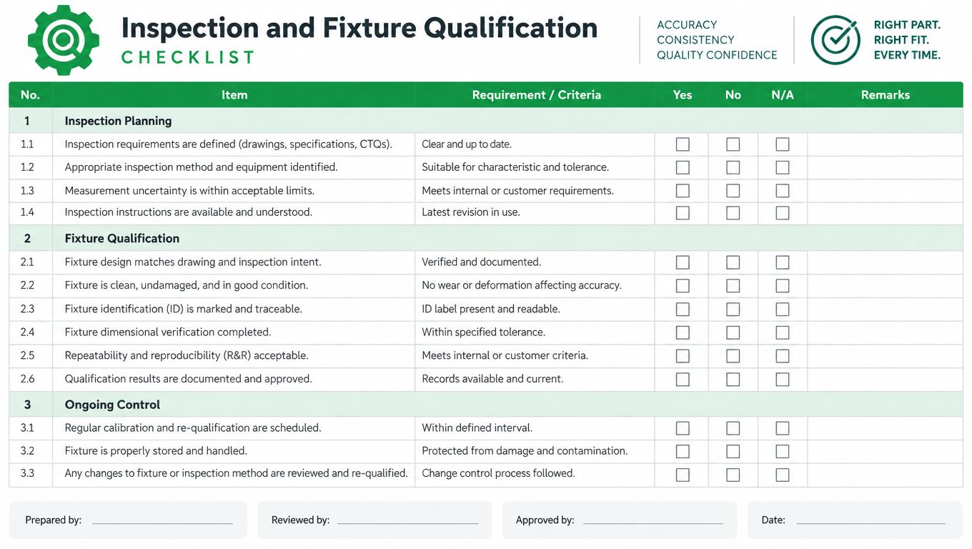
A first-article inspection tells you whether one loaded part met the drawing. It doesn't always tell you whether the fixture caused a datum shift, whether the clamp deflected the part, or whether the part itself is too flexible for the chosen locating scheme. Fixture qualification separates those effects by measuring the setup as a process.
A CMM-based fixture evaluation can measure coordinate-system relationships, locator positions, support locations, and changes caused by loading. The fixture-evaluation methodology treats fixturing error as a measurable quantity rather than a visual judgment. That matters when a tool will be reused across design iterations or when a small setup shift can consume the part's functional tolerance.
Measure the features that control the process
Don't begin by measuring every surface. Start with the features that define the part coordinate system and the features most sensitive to fixture variation.
- Measure the fixture datums: Check locator position, flatness, perpendicularity, pin condition, and replaceable wear surfaces.
- Record unloaded condition: Establish the fixture's reference state before clamping the workpiece.
- Load the part consistently: Follow the actual operator sequence, including cleaning, clamp order, and specified force.
- Measure loaded relationships: Look for datum shift, clamp deflection, support gaps, and movement at critical features.
- Repeat the loading cycle: A fixture that measures correctly once may still lack repeatable seating.
- Compare against functional datums: Judge the result using the part's drawing scheme, not an arbitrary fixture coordinate system.
A CMM isn't always necessary. A plug gauge may be sufficient for a loose hole requirement and a short run. A height gauge, optical comparator, or in-process probe may answer a narrower question quickly. The right method depends on part tolerance, fixture reuse, production volume, inspection uncertainty, and the cost of a wrong decision. Teams needing a structured external measurement workflow can review CMM inspection services.
Separate fixture error from part behavior
Thin plastic and sheet-metal parts can spring back or deform when clamped. If the fixture forces the part into an artificial shape, inspection may report a fixture-induced condition as if it were a machining defect. Conversely, a compliant part may appear acceptable in the fixture but fail after release.
Record whether the part is inspected while clamped or free. Note clamp force, contact condition, temperature, and loading sequence. Qualification should produce an acceptance record that states which fixture features were checked, what measurement method was used, what repeatability was observed, and when requalification is required after damage or modification.
Cost, Lead Time, and Lifecycle Tradeoffs
A fixture that costs less to build can still cost more to operate. Compare design, fabrication, changeover, maintenance, and requalification as one error chain, not as separate purchasing lines. A simple fixture may be cheap to make yet expensive to redesign, store, clean, repair, or validate after a product change.
Design cost covers datum planning, force and deformation analysis, CAD, drawing release, and review with the machinist or operator. Fabrication includes the base, locators, clamps, wear elements, surface treatment, inspection, and finishing. Changeover includes exchanging plates, adjusting stops, replacing nests, checking the new configuration, and correcting a loading mistake. Each activity can introduce variation that later appears in inspection data.
Price the workholding over its life
A dedicated fixture can reduce adjustment and simplify loading for one stable geometry. A configurable fixture may require more design work, but it can distribute tooling investment across variants and reduce exposure to redesign. As noted earlier, fixture strategy affects both capital investment and production flexibility, so procurement should request more than a single fabrication price.
Maintenance needs a written plan. Drill jigs require checks for guide-bushing wear. Milling fixtures need inspection of datum surfaces, locating pins, clamps, and supports. Repeated contact can create burrs or wear flats, while chips can prevent seating even when the hardware remains dimensionally correct. Store master parts, setup instructions, replacement-element drawings, and inspection records with the fixture. Operator memory is not a maintenance system.
Use a quote comparison that exposes hidden work
Ask each supplier to identify:
- Design assumptions: Which surfaces act as datums, and what loading sequence is expected?
- Included inspection: Are locator positions, finished surfaces, and loaded relationships verified?
- Change provisions: Can the fixture accept revised nests, pins, or plates?
- Maintenance items: Which parts are replaceable, and how will wear be detected?
- Requalification triggers: What happens after a crash, repair, geometry change, or long storage period?
- Operational cost: How long do loading, clamping, unclamping, cleaning, and changeover take?
A printed fixture may suit a quick fit check or light assembly aid, but sustained load, heat, abrasion, and chemical exposure can alter its dimensions or service life. A fabricated steel structure may withstand the service while adding handling and inspection work. Inspection results should decide whether that durability is worth its cost, rather than rigidity serving as the only selection criterion.
For NPI, reuse across design iterations can reduce lifecycle cost. A modular architecture can preserve the machine-side base, inspection references, and documented setup while the part-specific interface changes. Flexibility does not automatically make a fixture economical. Compare the avoided redesign and qualification work with the added adjustment, maintenance, and verification time before choosing replacement or reuse.
Outsourcing to a Precision Prototyping Partner
Give a supplier enough information to design the process, not just enough information to make a shape. Send fully toleranced CAD, the functional datum strategy, target run size, expected variants, critical surface finishes, machine envelope, clamping restrictions, inspection requirements, and the loading sequence you expect operators to follow.
Ask how the supplier will control locator position, clamp force, deformation, tool access, chip clearance, and inspection access. Request the machine and inspection capabilities relevant to the tolerance, along with evidence that the supplier has qualified similar workholding. A quote that never asks how the fixture will be used deserves closer review.
Look for these red flags:
- Missing datum callouts: The supplier must not guess which surfaces control the part.
- No force discussion: Clamping can shift or deform the workpiece.
- Ambiguous tolerancing: “Precision fixture” isn't an acceptance criterion.
- No change policy: NPI tools need a clear approach to revisions.
- No requalification plan: Damage and repairs can alter the error chain.
- No maintenance definition: Wear surfaces and replacement parts should be identifiable.
For programs that need bridge tooling or quick changes, compare conventional fabrication with rapid tooling services. FIRMFG offers CNC machining, additive manufacturing, sheet-metal fabrication, molding, casting, finishing, and inspection support for prototype and low-volume work, so engineers can evaluate fixture material and process choices against the same project requirements.
Before releasing a purchase order, make sure the supplier can answer one final question: How will the finished fixture prove that it places and holds the part the way the drawing requires?
If your next prototype or NPI build needs workholding designed around datums, inspection data, and future revisions, review the fixture requirements with FIRMFG. Share your part geometry, tolerance priorities, run profile, and expected changes so the team can recommend a practical combination of CNC machining, additive manufacturing, sheet metal, molding, or casting.