CNC Machining Aluminum: A Guide to Alloys and Tooling
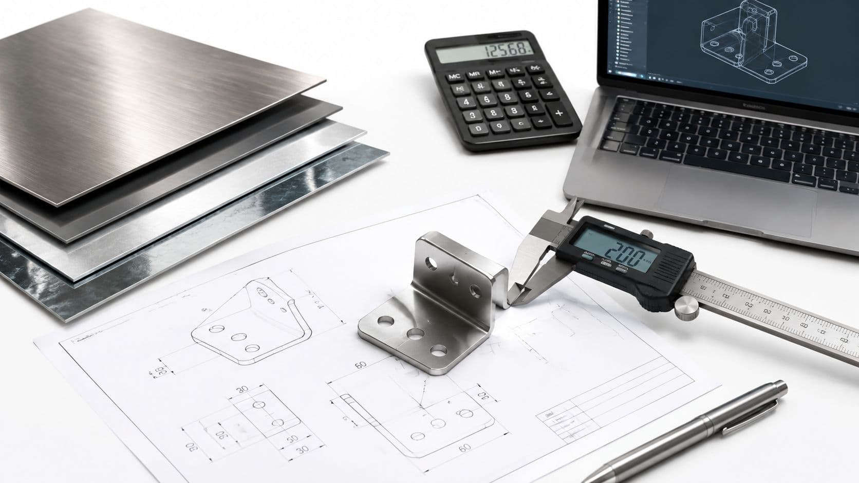
You're usually looking at a polished CAD model, a clean material callout, and a deadline that doesn't leave much room for trial and error. Then the first article comes back with chatter on a thin wall, burrs at the edges, and a finish note that changes the whole drawing package.
That's the world of CNC machining aluminum. The metal is forgiving in the spindle, but it's not forgiving after the cut if you missed the finishing allowance, the wall stiffness, or the inspection plan.
Table of Contents
- Why Aluminum Dominates Precision CNC Manufacturing
The shop-floor reason teams keep choosing it
Why the default alloy is usually 6061-T6
Choosing the Right Aluminum Alloy for Your Part- Compare the alloy to the function, not the brochure
Feeds and Speeds Strategies for Aluminum CNC Work- Use speed to form a chip, not polish a wall
Overcoming Common Aluminum Machining Challenges- Thin walls and chatter show up before the first part ships
- Burrs and pockets are usually a chip-control problem
- Thermal movement can ruin a flat that looked fine in CAM
Designing for Anodizing and Surface Finishing- Allowance is part of the design, not a shop correction
Tolerancing and Inspection for Aluminum CNC Parts- Write tolerances around the measurement plan
Scaling from Prototype to Low-Volume Production- Use the prototype to remove setup pain
Why Aluminum Dominates Precision CNC Manufacturing
A design team can hand over a clean bracket, enclosure, or heat sink, and the shop can still blow the schedule if the part was treated like steel. Aluminum stays popular because it cuts fast, works well with sharp tooling, and keeps the economics in a range that makes another revision possible without forcing a full program reset.

The shop-floor reason teams keep choosing it
One industry guide says aluminum can be machined 3 to 4 times faster than steel, with carbide tooling commonly running at 800 to 1,500 SFM (Bravo Fabs). That matters because machining time usually drives the bill more than the raw billet does. The same source puts machining time at 40 to 60% of total part cost, while raw aluminum stock is often only 5 to 15% of the total in CNC jobs.
That is why aluminum shows up first on prototypes, housings, fixtures, and low-to-mid volume production runs. It lets engineers cut quickly, inspect quickly, and revise quickly without turning every design change into a budget event.
The market scale reflects that reality. A 2025 market report estimated the global Aluminum CNC Machining Services market at USD 3,569.0 million and projected a 7.20% CAGR over the forecast period (MarketResearch.com). Analysts cited in the same report also describe a large aluminum processing base, with CNC aluminum machining occupying a major share of precision manufacturing applications.
Practical rule: if the part needs repeated revisions, tight machining access, and a realistic unit cost, aluminum is usually the first material to challenge before you move to something harder to cut.
Why the default alloy is usually 6061-T6
The same guide notes that 6061-T6 is the default choice for roughly 80% of CNC aluminum machining projects. That is shop logic, not branding. 6061 gives a good balance of strength, machinability, weldability, and cost, which is what most hardware teams need when the part has to work, fit, and ship.
Once the cut is done, the traps start. Thin walls can chatter during finish passes, leaving a surface that looks acceptable on the machine but moves out of spec after deburring or anodizing. Sharp internal corners and over-aggressive stock allowance can also create tolerance stack-up once the finishing process adds material or removes a little edge definition.
has a simple story behind it. Aluminum lets a machinist cut aggressively, a designer hold practical tolerances, and a buyer keep the cost structure under control. The harder lesson is that the part does not end when the spindle stops. Anodizing build-up, thin-wall deflection, and finishing-related tolerance drift can erase a clean machining result if they were not accounted for in the print. That is why the material keeps showing up in aerospace, robotics, medical devices, and electronics supply chains.
Choosing the Right Aluminum Alloy for Your Part
The alloy choice decides more than strength. It changes how the cutter sounds, how the surface breaks, how the part anodizes, and how much of your tolerance budget disappears during finishing. Most bad aluminum jobs start with the wrong alloy for the actual use case, not the wrong end mill.
Compare the alloy to the function, not the brochure
| CNC Aluminum Alloy Selection Matrix | Best For | Machinability | Anodizing Response | Key Limitation |
|---|---|---|---|---|
| 6061-T6 | General brackets, housings, fixtures, prototypes | Easy to machine, widely used in CNC work | Common choice for functional finishes | Not the highest strength option |
| 7075-T6 | High-stress aerospace and performance parts | Machines well, but with higher cutting load than 6061 | Can be finished, but cosmetic consistency needs more attention | Higher tool wear and less forgiving behavior |
| 5052 | Enclosures, formed parts, corrosion-focused hardware | Good for sheet-style work and practical machining | Often chosen where appearance and corrosion resistance matter | Not the go-to for high-stress structural parts |
| 2024 | Structural components with fatigue demand | Machinable, but more demanding than 6061 | Finish can be acceptable, but process control matters | Less universal than 6061 for general CNC work |
6061-T6 remains the default for a reason, and the earlier section already covered that market reality. Use it when the part needs a broad balance of machinability, strength, and cost without drama. It's the alloy you pick when the design is still changing or when the geometry has enough complexity that predictable cutting behavior matters more than chasing ultimate strength.
7075-T6 belongs on parts that really need higher strength-to-weight performance, especially where the load path is unforgiving. It's the right conversation for aerospace brackets and similar components, but the trade-off is that the machinist has less margin for heat, wear, and poor chip evacuation.
5052 earns its place in enclosures and parts that benefit from corrosion resistance and formability. If the design has a lot of cosmetic surface area or a sheet-metal adjacent workflow, it can make sense. 2024 is the alloy people reach for when fatigue behavior matters and the part sits closer to a structural duty cycle than to a generic enclosure.
Design takeaway: don't pick the alloy first and the finish second. Pick the function first, then check how that alloy behaves under machining and post-processing.
Feeds and Speeds Strategies for Aluminum CNC Work
Aluminum rewards confidence. If the tool is sharp, the chip is evacuated, and the spindle is running in the right window, the cut sounds clean and the finish usually follows. If the setup is timid, the tool rubs, chips smear, and the part starts teaching you why aluminum can look easy on paper and difficult on the machine.

Use speed to form a chip, not polish a wall
Expert machining guidance puts 6061-T6 cutting speeds around 1,200 m/min and 7075-T6 around 1,005 m/min with carbide tooling (Yueyi Precision). That gap reflects material behavior. 6061 is easier to machine, while 7075's higher strength raises cutting load and tool wear.
The same guide gives feed-per-tooth guidance that scales with tool size, from about 0.001 IPT for 1/8 in tools to 0.006 IPT for 3/4 in tools (Yueyi Precision). That's a useful way to think about aluminum. Smaller tools need enough chip load to cut cleanly, but larger tools can carry more aggressive engagement without rubbing.
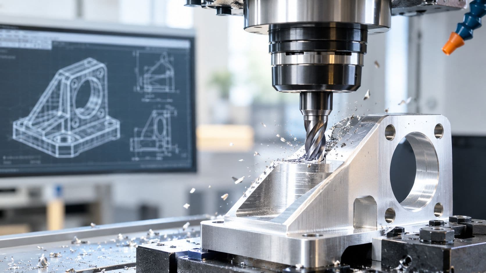
Climb milling is usually the first choice for most aluminum features because it helps with chip evacuation and surface quality. Conventional milling still has its place on certain thin or unstable features, but it shouldn't be the default just because it feels safer. In aluminum, slow often means worse.
Tooling and coolant should support evacuation
For end mills, 2-flute tools give the most chip room, while 3-flute cutters can balance strength and throughput in deeper work. Carbide is the standard for production work, because it keeps an edge at high speed and resists heat better than softer tool materials. Coatings still matter, but open flute geometry matters more if the cavity is deep and chip packing is the risk.
Coolant strategy should match the geometry. Flood coolant helps where heat and chip load are high. Mist and air blast can work well when the priority is clearing chips without over-wetting the setup. If chips recut, the surface goes downhill fast, and the cutter starts building up material instead of removing it.
Keep the chip short, dry enough to evacuate, and out of the cut. Recutting is a process problem, not a finishing problem.
Overcoming Common Aluminum Machining Challenges
The hardest aluminum parts are rarely the big, obvious ones. They're the thin-wall housings, the deep pockets, the cosmetic panels, and the parts that look simple until the machinist starts chasing deflection, burrs, or thermal movement. Those are the parts that turn a clean quote into rework if the design didn't leave enough stiffness or process margin.
Thin walls and chatter show up before the first part ships
For most milled features, a widely used rule is about 0.8 to 1.0 mm minimum wall thickness in aluminum, with about 0.5 to 0.7 mm only feasible in short, locally supported sections (Wevolver). Thin walls chatter because the cutter pushes them away from the tool, then the wall springs back and leaves a poor finish. The more unsupported the wall, the more the machine is cutting a moving target.
Use ribs and fillets where stiffness matters. That sounds basic, but it's the difference between a part that machines cleanly and one that needs a hand deburr and a second inspection pass. On larger flats, break the part into more stable machining stages instead of trying to finish everything in one aggressive pass.
Burrs and pockets are usually a chip-control problem
Burrs form where the tool exits a cut cleanly but the edge still plastically deforms. That shows up on intersections, thin tabs, and small holes where the cutter has too little support at exit. The fix is often a combination of tool geometry, exit strategy, and a deliberate deburr allowance in the drawing.
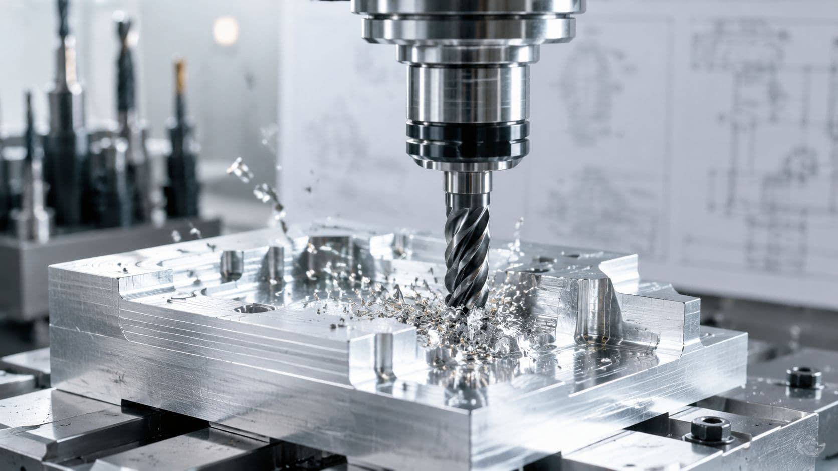
Deep pockets create a second problem. Chips collect, get recut, and leave the wall looking smeared instead of milled. Adaptive toolpaths help because they keep engagement more consistent and reduce the sudden load spikes that amplify chatter on thin features. Roughing strategy matters more than many expect.
Thermal movement can ruin a flat that looked fine in CAM
Aluminum moves with heat, and the effect is most obvious on large, thin, or asymmetrical parts. A finish pass that looks perfect in simulation can still drift if the part relaxed after roughing or the fixture let one section breathe differently from another. Sequencing matters, so a machinist will often rough, rest, and then finish critical surfaces after stress has settled.
That's also why the 5-axis setup conversation matters early. If the part can be reached with fewer setups, the machinist has fewer chances to chase accumulated error from one clamp to the next. For teams that need a full-service path from prototype to controlled low-volume work, one option is LC Proto, especially when the part needs CNC machining, surface finishing, and inspection in the same workflow.
Designing for Anodizing and Surface Finishing
Machining to final size is not the end of the story. Once anodizing or cosmetic finishing enters the route, the geometry changes, the edges change, and the inspection plan changes with it. That's where a lot of otherwise good aluminum parts fail, because the drawing treated finishing like decoration instead of a process step that affects fit.
Allowance is part of the design, not a shop correction
One guide notes that Type II anodizing commonly uses allowances of 5 to 25 µm per side, while Type III hardcoat can require 25 to 100 µm per side (Yueyi Precision). Anodizing consumes material and adds thickness, so mating features, slots, threads, and cosmetic edges all need to be thought through before the part ever gets cut.
That's especially important on press fits, locating bosses, and tight visual seams. If the part must assemble after finishing, the drawing should show the finish state as the functional state, not just the machined state. Cosmetic parts also need edge break and masking decisions written down early, because masking can leave visible transitions that look like defects if nobody expected them.
Surface finish targets should match the post-process plan
The same guide reports that as-machined aluminum commonly lands around Ra 0.8 to 3.2 µm, while polished or finishing operations can reach Ra 0.4 µm (Yueyi Precision). That range is useful because it tells you what machining can reasonably deliver before finishing starts changing the part.
Use Ra when the important issue is average roughness and cosmetic feel, and use Rz when peak-to-valley behavior matters for sealing or contact behavior. If the part is going to be brushed or polished, keep the drawing honest about that path instead of assuming the machining marks will disappear by accident.
Brushed finishes deserve their own discussion, which is why teams often pair this with a dedicated finishing reference like brush finishing aluminum expert techniques. Cosmetic consistency is hard enough without leaving finish direction, anodize type, and edge treatment open to interpretation.
Practical rule: specify the finish the part will ship in, not the finish it has when it leaves the mill.
Tolerancing and Inspection for Aluminum CNC Parts
Tolerances can save a launch or waste a budget. Aluminum is capable of excellent precision, but only when the geometry, fixture, and inspection plan all point in the same direction. If they don't, the drawing becomes an expensive request for the machine to do something the setup can't reliably repeat.
Write tolerances around the measurement plan
Independent design guidance says standard machining tolerances around ±0.10 mm to ±0.127 mm are typical, while tighter ±0.02 to 0.03 mm tolerances are possible only on selected features with strong fixturing, inspection, and controlled process conditions (Wevolver). That matters because tolerance only has value if someone can measure it the same way every time.
A tight callout on a buried feature doesn't help if the probe can't reach it cleanly. Likewise, a flatness requirement on a thin panel is only meaningful if the part can be fixtured in a way that doesn't distort it before inspection begins. The right tolerance is the one that matches actual function and actual access.
Inspect the feature that matters, not just the one that is easiest
A clean measurement report can hide a bad design if all the accessible dimensions pass while the functional stack-up still fails assembly. That's where CMM and scanning inspection help, because they can validate complex geometry instead of just checking a few convenient points. The point is to catch mismatch between design intent and manufactured reality before the part ships.
The most common mistake is over-tolerancing every face, hole, and pocket just because the part is important. That drives cost without necessarily improving fit. The second mistake is the opposite, leaving critical stack-ups vague and assuming the assembly team will sort it out later.
For a deeper reference on callout strategy, use complete guide to CNC machining tolerances. In practice, the winning parts are the ones where the drawing, fixture, and inspection routine were built as one system.
Scaling from Prototype to Low-Volume Production
Prototype parts show whether the concept works. Low-volume production shows whether the part can be built the same way again and again without the drawings, fixtures, and finishing steps drifting out of control. Aluminum can handle both stages, but the shop strategy changes once the job stops being a one-off.
Use the prototype to remove setup pain
Prototype quantities are the right time to expose parts that need several setups, awkward fixturing, or a lot of hand finishing. Multi-axis CNC reduces repositioning and usually improves consistency, especially on geometry with faces that can be reached in one clamping instead of two or three. Every extra setup adds another chance to stack tolerance error, and that shows up later when the part reaches finishing or inspection.
A prototype also shows where the hidden cost starts after machining. Anodizing can grow on edges and tighten a dimension that looked fine off the machine. Thin walls can move during deburr or finish prep, and a stack of small variations can turn into a fit problem once the part is assembled. If the team waits until production to see those effects, the batch only multiplies the problem.
The move from prototype to small batch should also force a review of finish and inspection as production controls, not afterthoughts. If the surface treatment, deburr method, and final inspection plan are stable, the part is much easier to repeat. If they are not, every additional part just repeats the same uncertainty and makes it harder to sort out whether the issue came from machining, finishing, or measurement.
Choose the manufacturing path that matches the batch size
For early iterations, low-volume CNC machining is often the cleanest path because it keeps design changes cheap and fast. Once the geometry is stable, a supplier that can handle CNC machining, surface finishing, and dimensional inspection in one place reduces handoff risk. LC Proto fits that model as one option, with 3-, 4-, and 5-axis machining, finishing, and inspection under a single workflow.
If the part is still changing, do not force production thinking too early. If the part is stable, judge the supplier on repeatability, communication, and whether the finish and inspection plan still match the drawing after anodizing, deburr, and final check. That line separates a prototype vendor from a production partner.