3D Printing Molds for Casting: Materials, Methods and Fixes
Your casting geometry is ready, but a delayed pattern can stall the project, especially when a revision changes an internal passage. 3D printing molds for casting can cut that tooling bottleneck. Design for cleaning, burnout, and pouring, since a mold that prints well can still crack, trap porosity, or drift during casting. Judge it by accepted castings, not print cost alone.
Table of Contents
Printing Methods and Materials by Casting Route- Match the material to its actual job
How to Design a Printed Mold Step by Step- Establish geometry and removal requirements
Surface Prep, Sealing and Coating Before You Pour- Prepare the surface without damaging the mold
Silicone Vacuum Casting for Low-Volume Replication- From finished master to reusable mold
Troubleshooting Warped, Cracked and Rough Molds- Diagnose shell failure before changing infill
Pick Your Route and Check Total Cost Per Casting- Calculate the accepted-part cost
Why Printed Molds Are Reaching the Foundry Floor
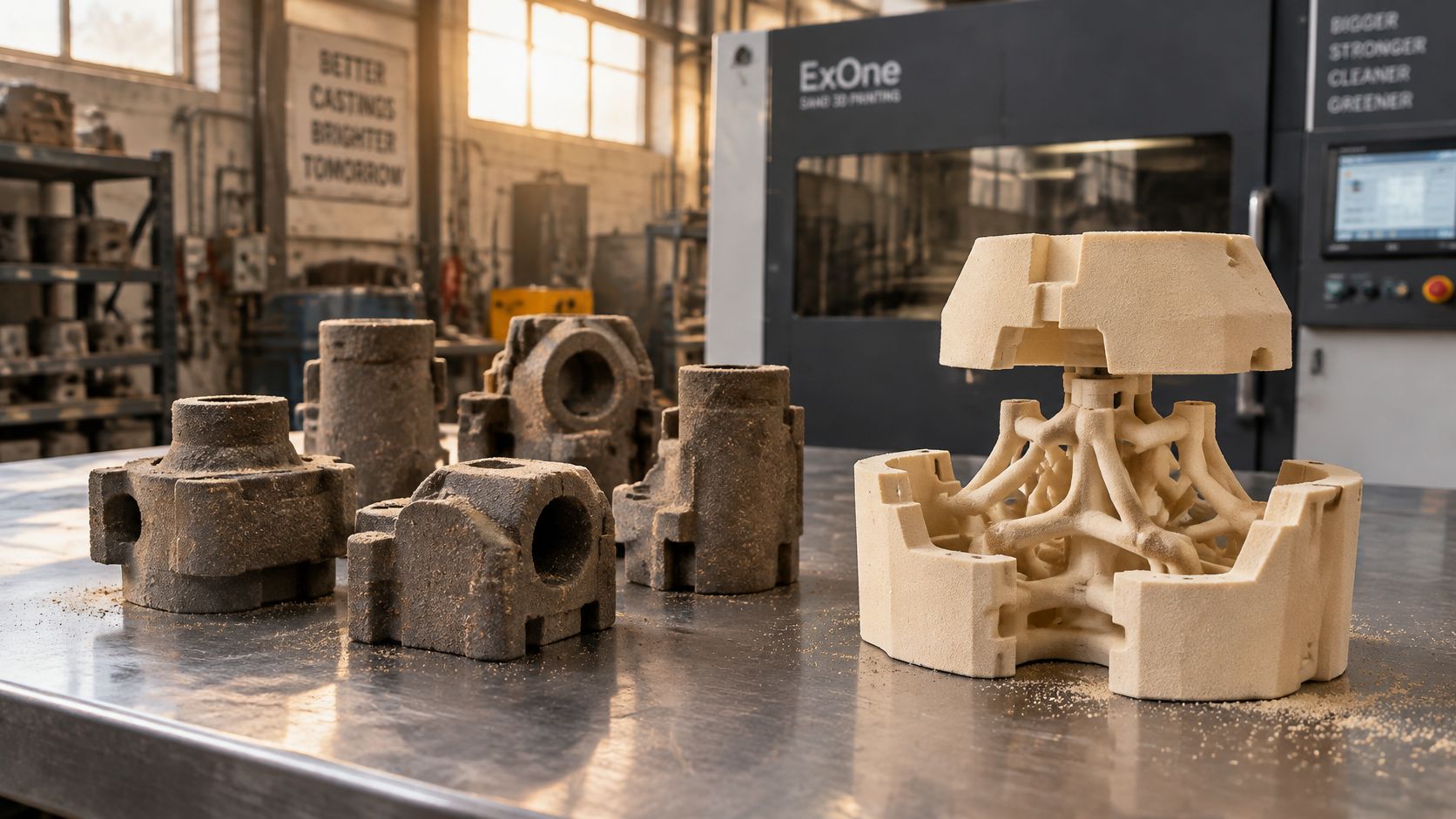
At Waupaca Foundry, researchers replaced a six-piece chemically bonded sand-core assembly with a three-piece printed assembly, and the printed cores achieved dimensional tolerances approximately one ISO 8062 grade tighter in a production trial documented by the American Foundry Society's Casting Source. Every casting underwent coordinate-measuring-machine inspection, so the comparison wasn't based on whether the parts merely looked acceptable.
The important change wasn't just better printing resolution. Consolidating the assembly removed interfaces where foundry workers previously had to position and join separate cores. Fewer joints mean fewer opportunities for mismatch, although fragile printed features still need handling support.
Know what you're actually printing
Three different tools often get called printed molds:
- Sacrificial pattern: A positive model surrounded by investment material, then removed through melting or burnout.
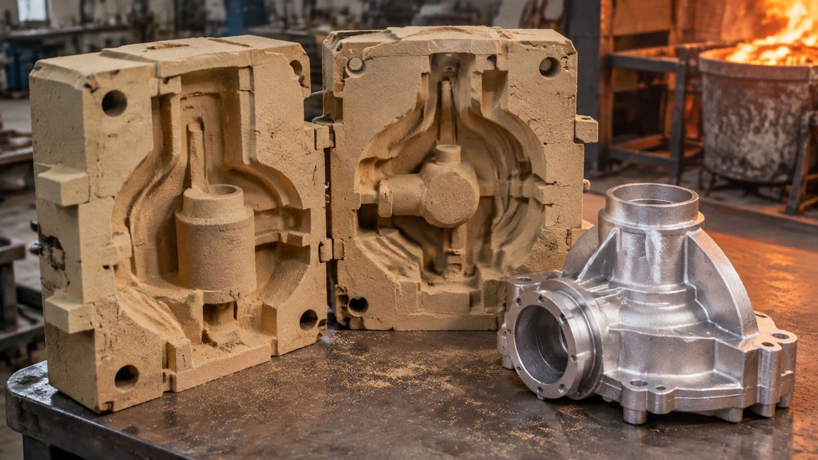
- Direct sand mold or core: The negative cavity or internal shaping element, printed directly from CAD and destroyed during shakeout.
- Reusable-mold master: A finished positive used to make a silicone mold, rather than exposed to molten metal.
Those distinctions matter because a beautiful resin master isn't automatically a suitable burnout pattern.
Printed sand also makes geometry possible that conventional patternmaking struggles to release. Oak Ridge National Laboratory's account of its Virginia Tech collaboration describes cast-aluminum lattice trusses approaching wire-like thickness, produced using printed sand molds without dedicated hard tooling.
Practical rule: Start with printing when complex geometry, frequent revisions or tooling delays dominate the job. Review conventional tooling when you're repeatedly making identical parts.
Printing doesn't replace foundry engineering. It changes which geometric restrictions you can remove and which process controls you must tighten.
Printing Methods and Materials by Casting Route
| Printing method | Printed item | Casting route | Typical material | Main limit |
|---|---|---|---|---|
| SLA resin | Investment-casting pattern | Jewelry and small precision metal parts | Burnout-capable photopolymer resin | Fine detail, but burnout gases require controlled extraction |
| SLS nylon | Pattern or sacrificial core | Qualified investment-casting applications with complex passages | PA12 nylon powder | No attached supports, but powder removal and burnout must be qualified |
| FDM | Rough pattern or jig | Rough sand or plaster casting | Thermoplastic filament | Visible layers; ordinary filament isn't a clean-burnout specification |
| Binder-jet sand printing | Sand mold and core | Iron and aluminum sand casting | Silica sand with inorganic or furan binder | Binder spread, fragile features and coating allowance |
| Metal printing, SLM or DMLS | Insert or tooling | Die-casting or molding inserts | Qualified tool steel, stainless steel or aluminum powder | High upfront cost; heat treatment and finish machining extend delivery |
| SLA or CNC master plus silicone | Reusable silicone mold | Polyurethane vacuum casting | Platinum-cure silicone and polyurethane resin | Mold replacement must be included in the production plan |
Choose the casting route first, then the mold material, then the printing method. Starting with a printer you already own can push you toward a pattern material that causes problems later in burnout or mold release.
For the lost-wax-style investment route, workers surround the expendable pattern with a ceramic shell and remove the pattern before pouring metal. Burnout cleanliness, expansion and gas release therefore matter more than a resin's advertised tensile strength.
Binder-jet sand printing takes a different route. The printer selectively bonds sand into the mold or core itself, so there's no polymer positive to remove from the casting cavity.
Match the material to its actual job
SLA works well when small lettering, edges and intricate surfaces matter, but standard display resin isn't interchangeable with casting resin. Likewise, PA12 can produce complicated shapes without attached support structures, but that doesn't establish its suitability for every investment system.
FDM is useful for pulled sand patterns, fixtures and mold boxes where finishing is manageable. Don't assume an ordinary thermoplastic pattern can disappear cleanly inside a ceramic shell.
For plastic replication, the master needs dimensional stability, a finish you can reproduce and compatibility with silicone curing. A guide to plastic for prototyping helps separate appearance requirements from the mechanical properties needed in the final component.
Before ordering, resolve these checks:
- Removal behavior: Will the positive be pulled, melted, burned out or left as permanent tooling?
- Thermal compatibility: Can the actual mold system withstand the alloy and its validated pouring conditions?
- Cleanout access: Can workers remove all loose powder from internal passages and confirm that they're clear?
A printable enclosed channel isn't necessarily a cleanable casting channel.
How to Design a Printed Mold Step by Step
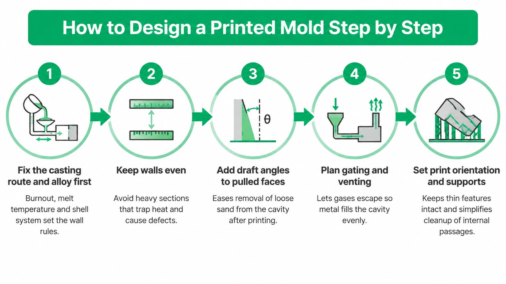
Design backward from the likely failure. A shell needs room to release decomposition products, a sand core needs enough strength to survive handling, and every critical passage needs an inspection method.
Establish geometry and removal requirements
- Fix the route and alloy. Record the alloy, molding system, pattern-removal method and critical dimensions on the job specification. A hollow resin pattern for investment casting and a printed sand core need different wall and vent strategies.
- Control section transitions. Keep pattern skins reasonably uniform and avoid abrupt heavy sections in the casting where the design allows. Where a boss meets a thin wall, use a gradual transition rather than treating the junction as a finishing problem.
- Add draft where something must be pulled. Pulled patterns and reusable molds benefit from release-friendly faces. Directly printed sacrificial sand cavities don't need conventional pattern draft merely because they're sand molds, and draft isn't a substitute for powder-cleanout access.
- Design hollow patterns for handling and burnout together. Place supports where workers can remove them without breaking the skin. Don't reduce internal structure until the pattern becomes too fragile to clean, invest or transport.
- Separate drainage from venting. Put drains where uncured resin or liquid pattern material can leave in the processing orientation. Put vents where gas becomes trapped during filling, including blind ends and local high points.
- Resolve parting, gating and support. Locate parting lines away from critical sealing faces where possible. Give thin cores secure seating, and arrange gates so incoming metal doesn't strike an unsupported feature directly.
Control the process before adding compensation
- Set binder zones deliberately. Strong interior bonding and restrained surface deposition can be more useful than uniform saturation. A grayscale binder-jetting study published by Springer reported a 59% reduction in Z-direction dimensional deviation when near-surface grayscale was reduced from 7 to 3 at a 0.5 mm layer thickness, compared with grayscale 7 throughout.
Treat that result as evidence for zoned parameter development, not a universal printer recipe. Binder chemistry, sand and machine controls still require qualification. - Apply measured CAD compensation. Print a representative feature, measure its deviation and establish whether the error repeats. Compensating for an unstable process only hides the problem until the next build.
Before final inspection, review pattern structure, vent area, drainage and shell permeability together. Qualify a representative shell through the intended burnout cycle and check its condition before committing the full run. - Inspect after depowdering. Use a coordinate-measuring machine, optical scan, gauges or a borescope according to the feature. Record critical cavity dimensions before coating, then verify that finishing hasn't blocked a passage or changed a core seat.
A good mold design is one you can clean, inspect and handle. Successful printing is only the first acceptance check.
Include accessible reference surfaces in the CAD model. Without them, workers may struggle to distinguish actual distortion from inconsistent measurement setup.
Surface Prep, Sealing and Coating Before You Pour
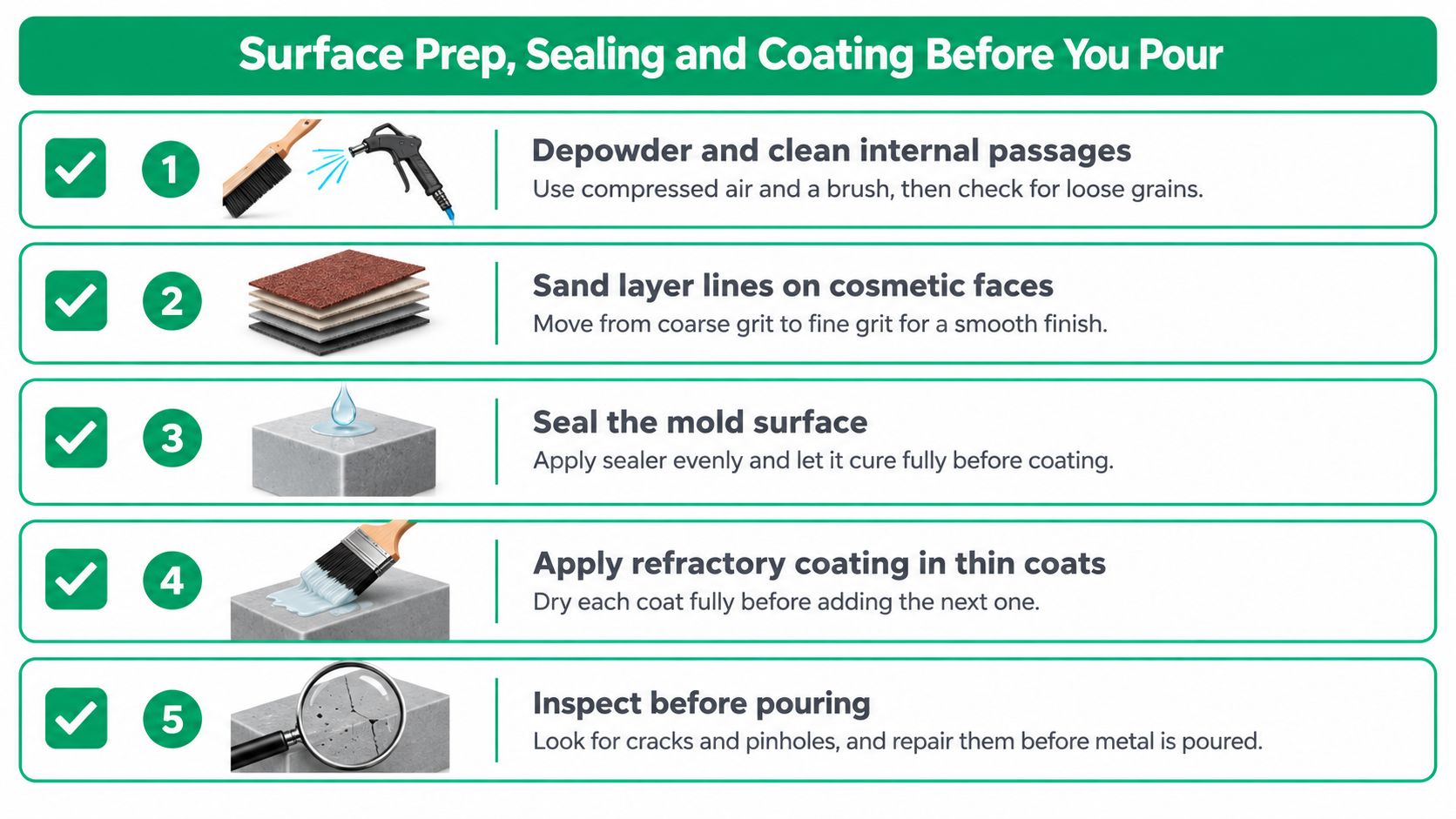
Finishing must suit the route. A resin master can be sanded and sealed for silicone molding; a bonded-sand cavity needs much gentler treatment and a qualified refractory system, not a coat of general-purpose varnish.
Prepare the surface without damaging the mold
- Clean first: Use a soft brush and suitable extraction to remove loose material. Where compressed air is permitted, use controlled pressure inside an extracted enclosure, not an open blast that spreads respirable dust through the workshop.
- Finish the correct surfaces: Sand support marks and layer lines on durable masters, working from coarser abrasives toward finer ones. Don't aggressively sand a fragile sand cavity and expect its dimensions to remain unchanged.
- Seal selectively: Use a silicone-compatible sealer on a porous master when required. For a metal-casting sand mold, use the qualified foundry coating system rather than adding an unapproved gas-generating layer.
- Apply controlled coating: Keep refractory coverage uniform, clear vents and dry the mold completely. Include the coating build in the cavity allowance.
- Check release compatibility: For silicone molding, test the master, sealer and release agent together on a small area. Pooled release can obscure detail, while incompatible residues can inhibit cure.
For support removal and finish selection, 3D printing post-processing should be planned before the master is printed. Otherwise, supports can land on the very face you're trying to reproduce.
Control the pour, not just the printer
In the specific rapid-sand-casting analysis summarized by a review hosted on HAL, pouring temperature contributed 97.55% of measured surface-roughness variation, compared with approximately 2% for shell-wall thickness. That finding isn't a universal allocation for every foundry, but it explains why a finer print alone may fail to improve the casting.
Keep superheat inside the validated alloy-and-binder window. Raising temperature to cure an incomplete fill can worsen surface penetration or gas-related defects if the actual restriction is poor gating.
Orient cosmetic faces consistently relative to the recoater, and inspect texture in the actual build direction. A horizontal test coupon won't necessarily represent a differently oriented cavity wall.
Finally, qualify the full thermal cycle on a representative sample. Check coating integrity, edges and locating features after heating, not only before it, and never pour into a mold with unresolved moisture or cracking.
Silicone Vacuum Casting for Low-Volume Replication
Silicone vacuum casting is a plastic replication route, not a substitute for an iron or aluminum sand mold. It uses a printed or machined positive to create reusable flexible tooling, then reproduces that geometry in polyurethane.
The practical advantage is that workers finish the master once rather than finishing every printed copy individually. That advantage disappears if the master contains defects that every subsequent part reproduces.
From finished master to reusable mold
Master preparation comes first. SLA suits intricate geometry, while CNC machining can provide controlled datum surfaces and clean, accessible features. Remove support scars, confirm dimensions and finish the master to the texture required on the cast part.
Mold creation follows. Secure the master in a mold box, establish the planned split and degas the mixed platinum-cure silicone. Vacuum processing removes entrained air, but it doesn't correct a poorly positioned master or an inaccessible pocket.
Opening the cured mold requires planning. Cut the split so the master can be removed without leaving a thin, easily torn silicone tongue. Registration features and a supporting box help workers close the halves consistently.
Casting completes the chain. Meter and mix the polyurethane, fill under the qualified vacuum process and cure at the resin's specified conditions. Some systems use a warm oven, but an arbitrary higher temperature can change cure behavior or mold life.
Plan around release and material behavior
The mold works a little like a waffle iron: the same cavity produces another copy each time, but the flexible tooling eventually wears. Replacement timing should follow actual tear damage, surface deterioration and dimensional results, rather than a promise that every geometry achieves the same life.
- Functional prototypes: Select the resin against the actual load, temperature and exposure.
- Bridge builds: Preserve the master and document finishing so replacement molds remain consistent.
- Appearance models: Approve texture and color on an early casting.
- Trial assembly: Inspect mating features and shrinkage against the drawing, not just against the master.
Material caution: ABS-like and polypropylene-like polyurethane describe a target behavior. They don't establish equivalence to the production thermoplastic.
Deep undercuts also need restraint. Silicone flexibility can release geometry that rigid tooling can't, but repeated stretching around a sharp hook can tear the mold long before its broad surfaces deteriorate.
Troubleshooting Warped, Cracked and Rough Molds
Change one variable per trial and keep the build file, orientation, material batch, finishing record and pour conditions together. Without that log, a better casting doesn't tell you which change worked.
Use the symptom to decide where to inspect first. The causes below are starting hypotheses, not permission to alter every setting at once.
| Symptom | Likely cause | Fix |
|---|---|---|
| Mold warps or drifts out of tolerance | Binder spread, uneven curing or thermal distortion | Check build-stage dimensions; tune surface binder and layer settings before measured compensation |
| Rough cast surface with sand grains | Excess superheat, coating failure or erosion | Inspect coating coverage and gate impingement; verify pouring temperature |
| Shell cracks during burnout | Restricted gas release, pattern expansion or inadequate shell strength | Inspect crack location; qualify vents, pattern structure and burnout ramp together |
| Blowholes or porosity | Trapped gas, poor permeability, moisture or melt-related causes | Confirm dryness and vent continuity; distinguish gas defects from shrinkage |
| Silicone mold tears or splits | Thin ligaments, deep undercuts or premature demolding | Strengthen vulnerable sections and revise the split or release direction |
| Visible layer lines on cast part | Unfinished master or coarse printed texture | Finish the master, or revise print orientation and layer settings |
| Mold deforms in the kiln | Material or thermal cycle unsuitable for the intended route | Verify the material specification and test the complete qualified heat cycle |
Diagnose shell failure before changing infill
A PLOS ONE study of SLA patterns for SUS 304 investment casting identified infill below 20% as a practical range for higher-quality hollow structures in its tested system and linked shell cracking, poor permeability, blowholes and porosity. That isn't a universal instruction to make every pattern as hollow as possible.
A weak pattern can crack during handling before shell building even starts. Conversely, adding internal material can increase the burden during burnout, so raising infill isn't an automatic cure for a cracked shell.
Check where failure begins. Cracks beside a heavy pattern junction call for a different response from cracks around a poorly supported shell feature.
Use the cheapest diagnostic before the biggest adjustment
Inspect the mold before pouring another casting. A scan can identify geometric drift, a borescope can reveal trapped powder, and careful examination can expose a blocked vent or coating bridge.
Start with print settings when the defect already exists in the unpoured mold. Revise geometry when the same feature repeatedly fails despite stable settings, and change pouring conditions only when the evidence points to filling or thermal behavior.
Temperature is easy to adjust and easy to over-adjust. Don't use hotter metal to conceal a venting, gating or moisture problem.
Pick Your Route and Check Total Cost Per Casting
| Volume need | Best route to evaluate | Trade-off to check |
|---|---|---|
| One-off metal test parts | Directly printed sand mold or sacrificial pattern | Avoided tooling versus mold preparation and inspection labor |
| Small batches of similar plastic parts | Printed master with silicone vacuum casting | Replacement molds, resin suitability and dimensional consistency |
| Growing runs of identical plastic parts | Silicone batches compared with injection tooling | Cumulative labor and mold replacement versus tooling investment |
| Sustained repeat production | Conventional or metal tooling, with printed cores where justified | Tool amortization versus continuing geometric or scheduling advantages |
Volume isn't a stand-alone decision rule. A complex internal core may remain worth printing during repeat production, while a simple, stable shape can justify reusable tooling much earlier.
Material also limits the comparison. Silicone-cast polyurethane, injection-molded polypropylene and cast aluminum aren't interchangeable purchasing options just because their external geometry matches.
Calculate the accepted-part cost
Use this basis:
Total cost per accepted casting = total run cost divided by castings that pass inspection.
Include design preparation, masters or tooling, printing, consumables, cleaning, coating, burnout, melting, finishing, inspection, rework, scrap and waste handling. Charge replacement molds and failed first articles to the run rather than treating them as somebody else's development expense.
For polyurethane projects, a vacuum casting cost breakdown helps separate tooling expenditure from repeated casting and finishing costs. Compare quotes at the same acceptance criteria, surface specification and delivered quantity.
Environmental savings also need a defined comparison. A lifecycle assessment of adaptive printed sand-mold structures reported carbon-emission reductions of 9.2% for a small furnace cover and 11.9% for a medium engine block, with modeled cost reductions of 6.7% and 11.1%, respectively.
Those results support mold optimization, not a blanket claim that printing is greener. Check printing energy, binder consumption, sand reclamation and rejected castings against the actual alternative.
Include handling and qualification in the purchase
Burnout extraction, controlled thermal schedules and residue disposal belong in the process budget. A cheap pattern isn't cheap if its decomposition products require extra handling or its residue causes rejected castings.
Our workflow starts with CAD upload and a quote within 24 hours, followed by master creation, silicone molding and casting, then inspection and shipping. Send the drawing alongside the model so functional tolerances don't get mistaken for cosmetic preferences.
Before releasing the job:
- Confirm the route: Identify the required final material and the role of the printed item.
- Define acceptance: Specify critical dimensions, finish and functional checks.
- Price the complete run: Include spare molds, tooling maintenance and expected rework.
- Require a first article: Approve a representative part before committing the remaining production.
Choose the process that delivers acceptable parts reliably, not the one with the cheapest printed object.
FIRMFG offers silicone-mold vacuum casting for small-batch, high-quality replication from a finished master. Visit FIRMFG with your CAD files, target material, quantity and critical dimensions to discuss whether a printed master and polyurethane casting fit your next build.