Plastic for Prototyping: Material Guide
The most popular advice about plastic for prototyping is also one of the least reliable: choose the resin name that matches the intended production part. A 3D-printed ABS part isn't automatically equivalent to injection-molded ABS, and a nylon prototype may tell you very little about a production assembly if humidity, layer orientation, or processing history changes the failure mode.
A prototype earns its place by answering a specific engineering question. Does the housing fit? Will the snap fit survive repeated use? Does the bracket creep under load? Does the material tolerate heat, cleaning chemicals, or sterilization? The right plastic and process depend on that question, not on a generic material ranking.
Table of Contents
- Why Resin Names Do Not Guarantee Prototype Performance
Chemistry is only one part of the result
Start with the decision the prototype must support
The Scale and Maturity of the Prototyping Plastics Supply Chain- Abundance creates choice, not simplicity
Comparing Additive, Subtractive, and Molding Processes- Additive processes suit early learning
Navigating Mechanical Datasheets and Hidden Environmental Variables- Build orientation changes the load path
Bridging the Gap from Prototype to Low-Volume Production- Choose the bridge by the decision, not the batch label
Design for Manufacturability Rules for Plastic Components- Keep the structure predictable
Consolidating Your Prototyping and Finishing Workflows- Connect process choices to inspection
Why Resin Names Do Not Guarantee Prototype Performance
A resin name describes chemistry. It doesn't describe the complete part.
An injection-molded ABS housing has a different thermal history, internal structure, surface condition, and strength profile from an FDM ABS housing. The printed part contains deposited roads and interfaces between layers. Those interfaces can become the weakest path through a bracket, boss, hinge, or fastener feature, even when the material datasheet looks reassuring.
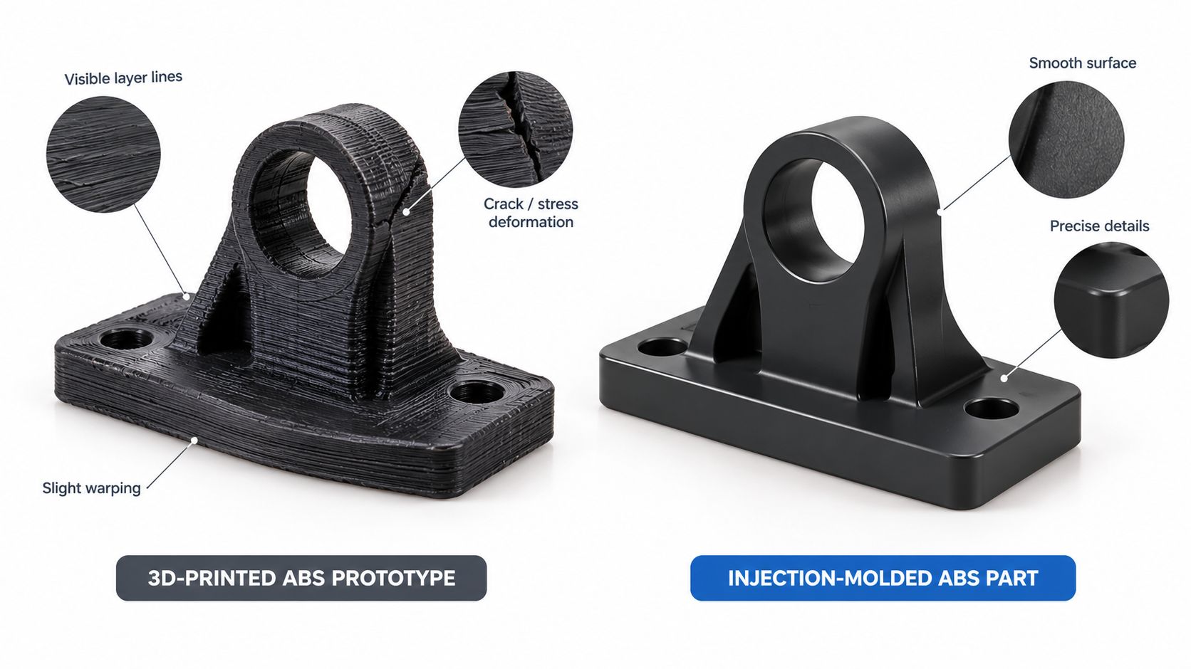
Chemistry is only one part of the result
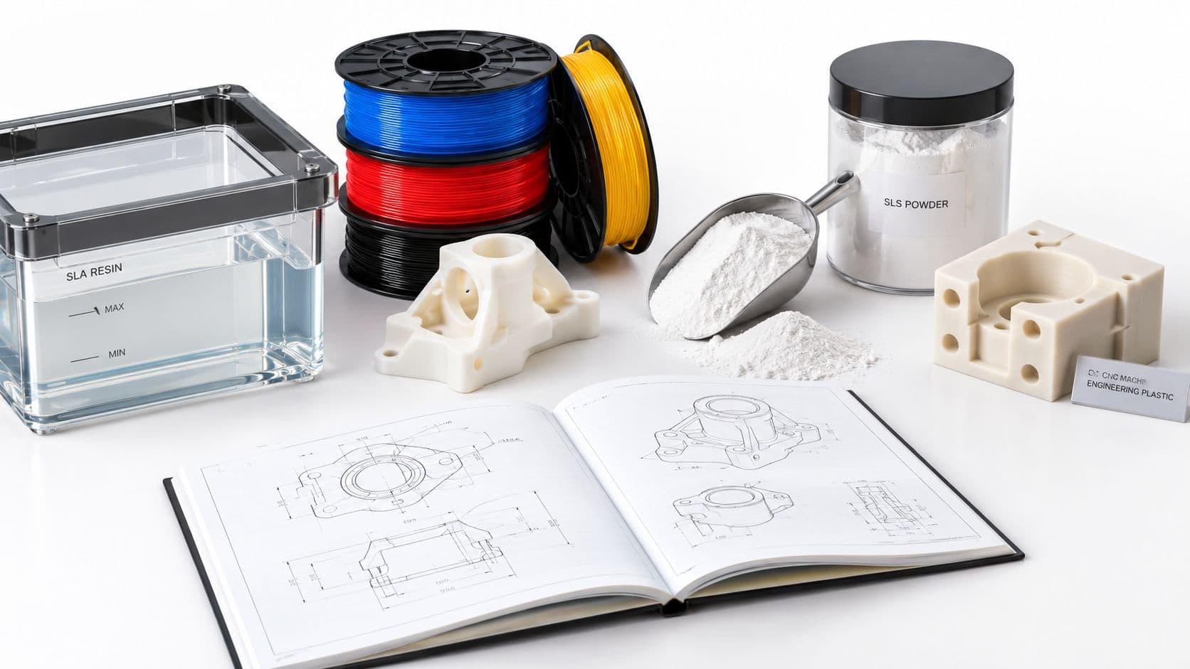
The manufacturing route controls how the material is arranged inside the part. FDM introduces anisotropy, because strength along deposited roads can differ from strength across layer boundaries. SLA creates parts through photopolymer curing, so post-curing, resin chemistry, wall thickness, and exposure history affect the result. SLS avoids conventional support structures, but powder fusion and thermal conditions still influence density, surface texture, and mechanical response.
A 2025 review notes that polymer 3D-printing quality depends strongly on build orientation and that anisotropy can reduce performance in complex parts. The same review identifies material separation, contamination, additives, and coatings as constraints when recycling printed waste, a reminder that the process affects both performance and end-of-life handling in its review of polymer 3D printing.
Practical rule: Match the prototype process to the failure mode you need to observe, not merely to the label on the production resin.
Start with the decision the prototype must support
A visual model can use a process chosen for surface quality and speed. A fit-and-form part needs dimensional control at mating surfaces. A functional test part may need production-like stiffness, creep behavior, fatigue response, chemical resistance, or heat performance.
Those objectives can conflict. A smooth SLA model may be excellent for evaluating a user interface or enclosure appearance, yet unsuitable for validating a threaded insert under repeated torque. A fast FDM print may reveal interference between components, but its layer direction can conceal the strength behavior of a molded part.
Write the validation question before choosing the material:
- Geometry: Can components assemble, move, and clear one another?
- Mechanical load: Does the part survive tension, bending, impact, or repeated cycling?
- Environment: Does it remain stable after heat, humidity, cleaning, or chemical exposure?
- Production transfer: Will the prototype reveal issues that also exist in molding, machining, or the planned production process?
The cheapest prototype is often the least informative when it answers the wrong question.
The Scale and Maturity of the Prototyping Plastics Supply Chain
Engineers have access to ABS, nylon, polycarbonate, polyethylene, reinforced polymers, high-temperature resins, powders, filaments, liquid photopolymers, and machining stock because plastics have a long industrial history. The modern prototyping ecosystem didn't emerge from hobby printing alone. It grew from materials and processes developed for demanding production applications.
Bakelite, reported by Leo Baekeland in 1907, was the first fully synthetic thermoset plastic. Industrial capability followed through developments such as a commercial modern injection-molding machine patented in 1926, practical industrial polyethylene discovered in 1933, nylon invented and patented in 1935, and the first thermoplastics extruder produced in Germany in the same year. ABS copolymers entered the market during the 1950s, expanding the practical choices for durable housings, fixtures, and functional prototypes, as documented in the University of Birmingham plastics development timeline.
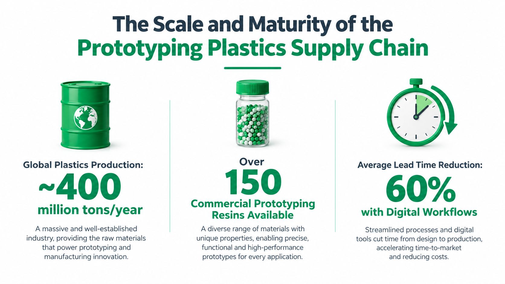
Abundance creates choice, not simplicity
The OECD reports that annual plastics production rose from 234 million tonnes in 2000 to 460 million tonnes in 2019, an almost twofold increase over 19 years. The same OECD plastics outlook reports that China accounts for approximately 20% of global plastics demand.
That scale supports a mature supply chain for commodity and engineering resins, semi-finished stock, filament, powder, molding compounds, and liquid systems. It also creates a selection problem. Two materials may both be described as nylon or polycarbonate while differing in reinforcement, additives, viscosity, moisture condition, processing window, and target application.
The resin's availability can influence your choice, but it shouldn't decide the choice by itself. A widely stocked grade may be practical for a fit check, while a less common engineering grade may be necessary to reproduce service temperature or chemical exposure. Ask the supplier for the exact grade, processing method, conditioning requirements, and relevant test direction.
Mature materials still need responsible selection
Plastic's industrial maturity doesn't make every prototype representative. The OECD's production data also underline why end-of-life planning matters. Select recycled content where it fits the validation purpose, document whether the prototype uses virgin or recycled feedstock, and avoid treating a material substitution as neutral when the part's stiffness, dimensional stability, or chemical behavior matters.
The useful consequence of this mature ecosystem is flexibility. Teams can choose a process and grade that reflect the next design decision instead of accepting whatever plastic happens to be loaded into a printer.
Comparing Additive, Subtractive, and Molding Processes
No single process is the default answer for every prototype. Additive methods excel at speed and geometric freedom. CNC machining exposes the behavior of a solid engineering-plastic blank with strong dimensional control. Molding becomes more valuable when the team must evaluate production-like flow, shrinkage, parting lines, gates, or a real thermoplastic grade.
| Process | Strength Profile | Surface Finish | Ideal Validation Stage |
|---|---|---|---|
| FDM | Direction-dependent, with layer bonding controlling weakness | Visible layer lines unless finished | Early fit checks, fixtures, simple functional trials |
| SLA | Good detail and fine feature definition, but resin behavior depends on cure and formulation | Smooth, presentation-friendly surfaces | Appearance models, fine features, ergonomic evaluation |
| SLS | Useful for complex geometries without conventional support structures | Textured, generally less polished than SLA | Functional geometry checks and complex housings |
| CNC machining | Strong representation of the selected stock material, with process-dependent but generally more uniform behavior | Machined surfaces, with finish controlled by tooling and strategy | Tight-tolerance assemblies and demanding mechanical checks |
| Prototype molding | Closest representation of molded geometry and production resin behavior | Mold-dependent, including texture and parting features | Process validation, material validation, and bridge builds |
Additive processes suit early learning
FDM works well when the team needs a quick bracket, enclosure, jig, or clearance model and can control the load path around the layers. SLA is a stronger choice when small details, lettering, ergonomic surfaces, or visual presentation matter. SLS is useful for enclosed geometries and complex shapes where support removal would complicate an FDM or SLA build.
The limitation is interpretive. A successful printed part proves that a particular printed construction survived a particular test. It doesn't automatically prove that a molded or machined production part will behave the same way.
Machining reveals different evidence
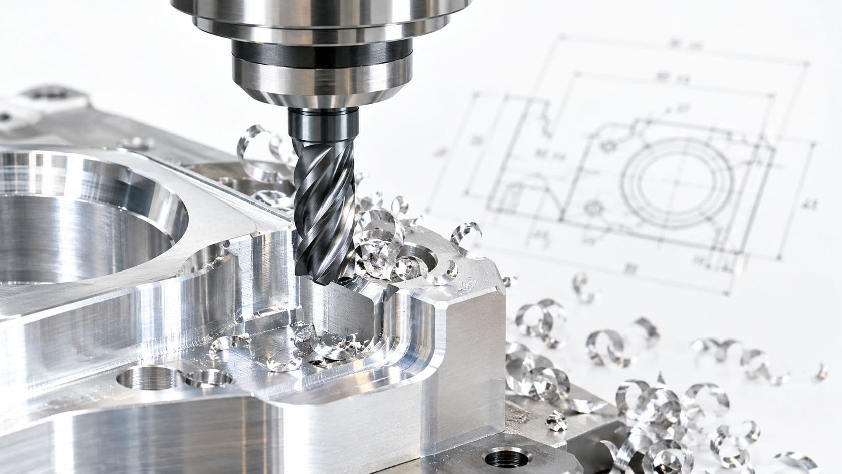
CNC machining a part from engineering plastic removes the interlayer-bonding variable and can provide a more representative check of solid-material stiffness, fit, and tolerance. It still won't reproduce molded shrinkage, weld lines, fiber orientation, or gate effects, but it can be the right method for validating a bearing seat, threaded interface, seal groove, or load-bearing bracket when the material itself matters more than the molding process.
Teams comparing additive and subtractive methods should also review CNC machining versus 3D printing in the context of geometry, tolerances, surface finish, and test purpose.
Molding becomes relevant sooner than many teams expect
Prototype or low-volume molding makes sense when the part's behavior depends on injection pressure, cooling, shrinkage, draft, weld lines, or the exact production thermoplastic. It can expose issues that a printed shell cannot, especially around snap fits, thin walls, bosses, and cosmetic surfaces.
Use a decision sequence rather than a process preference:
- Need visual or ergonomic feedback? Choose a high-detail additive process or a finished machined model.
- Need fit and assembly feedback? Choose the process that can hold the relevant interfaces and represent the expected material behavior.
- Need load, heat, chemical, or fatigue evidence? Use a process and grade that reproduce the expected failure modes, then test representative coupons or parts.
- Need production transfer evidence? Introduce molding before design freeze, because the molded process can create failures that additive prototypes never reveal.
Navigating Mechanical Datasheets and Hidden Environmental Variables
A datasheet is a starting point, not a guarantee. Read every mechanical value alongside its test direction, temperature, conditioning state, specimen geometry, and process details. If those conditions don't match your prototype, the number may describe the material but not your part.
Build orientation changes the load path
For FDM prototypes, orientation is a mechanical-design variable. One comparative study reported ultimate tensile strength for ULTEM 1010 of 81 MPa in the XY direction versus 48 MPa in the ZX direction, while ULTEM 9085 measured 69 MPa versus 42 MPa, respectively, in those directions in the reported comparison of FDM materials_2020_1157-1167.pdf).
The difference comes from weaker interlayer bonding and discontinuities between deposited roads. A load-bearing design should place its principal tensile stress in the stronger plane whenever the geometry allows, but that decision must be verified rather than assumed. Ribs, holes, thin walls, infill, surface treatment, and thermal history can all change local performance.
Print coupons using the intended layer height, raster strategy, and orientation. Test them in both XY and ZX directions, especially when the part will carry fasteners, snap fits, pressure loads, or repeated cycles. For high-temperature or safety-relevant work, test at the expected service temperature instead of relying only on room-temperature values.
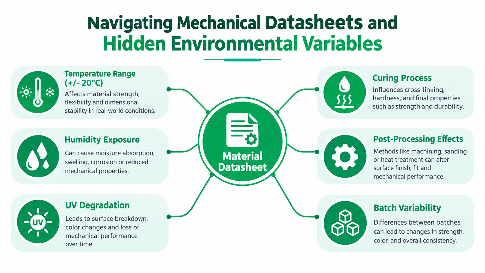
Moisture can invalidate a precision fit
Nylon deserves separate treatment because it absorbs moisture. Reported engineering data identify roughly 9–10% water absorption at saturation and approximately 2–3% linear expansion, which means a 30 mm feature can grow by about 0.6 mm, far beyond a ±0.02 mm fit tolerance as described in this material-selection guidance.
The absorbed water plasticizes the polymer chains, increasing molecular mobility, reducing stiffness, and changing dimensions. Humid storage, aqueous cleaning, and temperature cycling can make an initially accurate part unsuitable for a bearing, seal, mating housing, or calibrated interface.
Use a defined conditioning procedure:
- Control the starting state: Dry nylon according to the resin supplier's process window and store it in sealed packaging with desiccant.
- Condition before inspection: Measure the part after exposure to the humidity and temperature expected in service.
- Recheck critical interfaces: Reinspect seal grooves, bearing seats, hole patterns, and mating housings after conditioning.
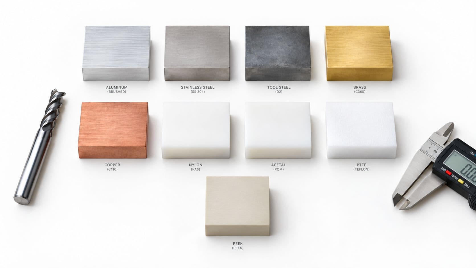
- Compare alternatives carefully: PEEK, PEI, PPSU, or PC may offer lower moisture sensitivity, but thermal expansion, creep, processing requirements, and cost still need review.
Inspection rule: A tolerance has meaning only when the part's environmental condition is recorded.
Bridging the Gap from Prototype to Low-Volume Production
The transition from a validated prototype to sellable parts is where many hardware teams lose time. A printed part may prove the geometry, but it doesn't necessarily provide the surface, material, dimensional behavior, or assembly repeatability needed for a pilot build.
The bridge should follow the evidence required at each stage. If the next question concerns appearance and user handling, vacuum casting with polyurethane can replicate a finished master for small-batch evaluation. If the next question concerns the actual production thermoplastic, rapid tooling and low-volume injection molding provide more relevant evidence.
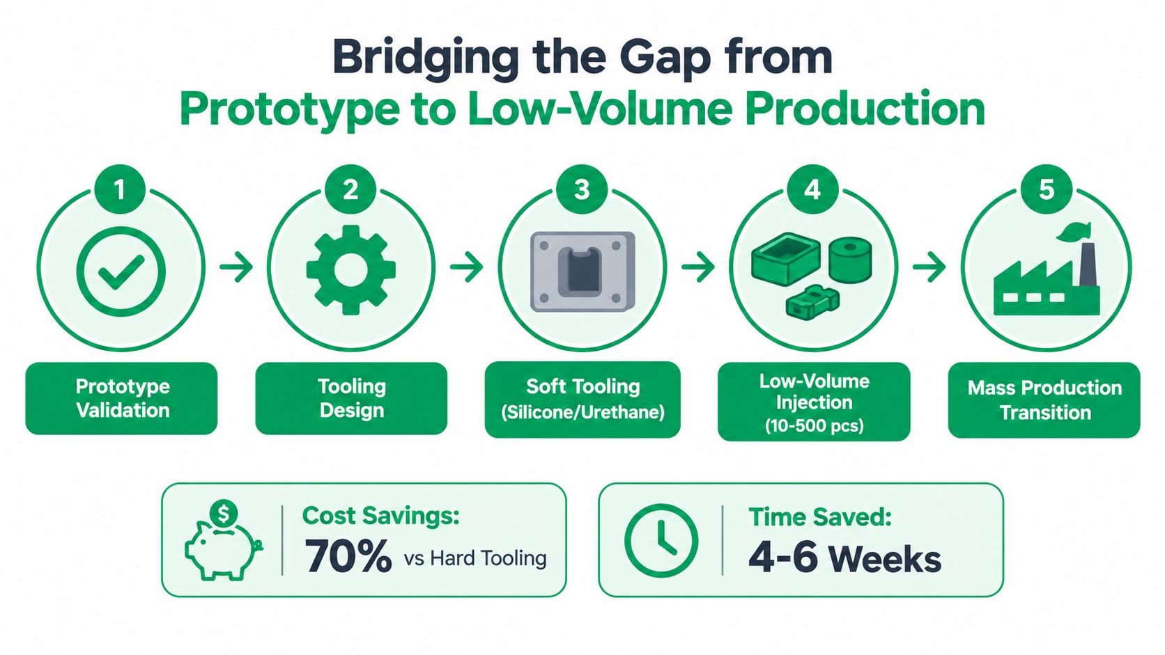
Choose the bridge by the decision, not the batch label
Vacuum casting uses a master pattern and a silicone mold to produce polyurethane replicas. It suits appearance models, ergonomic studies, early customer evaluation, and small batches where the production resin isn't yet the main question. The replicas can include finishes and color treatments that make them useful for handling and presentation, but polyurethane behavior shouldn't be mistaken for injection-molded ABS, PC, or nylon.
Low-volume injection molding is the better bridge when teams need production-like thermoplastic behavior. Aluminum prototype tooling can support real molding trials while allowing the design team to learn about fill, cooling, shrinkage, draft, ejection, weld lines, and cosmetic defects before committing to final tooling. Review low-volume injection molding options when the part has moved beyond geometry validation and into repeatable functional builds.
Preserve the geometry that matters
Design the first prototype with its likely manufacturing route in mind. Keep sealing surfaces, mounting datums, critical wall relationships, and assembly interfaces clearly identified. Avoid validating a part only through cosmetic features that will change during tooling or finishing.
A practical handoff package includes:
- Critical characteristics: Mark the dimensions, surfaces, and interfaces that must remain stable across processes.
- Material intent: State whether the prototype is for visual evaluation, functional loading, environmental exposure, or production-material comparison.
- Process assumptions: Record orientation, post-processing, conditioning, and any inserts or secondary operations.
- Test evidence: Attach measurements and failure observations to the revision, not just photographs of the finished part.
The bridge process should reduce uncertainty, not merely produce more units. If a vacuum-cast part passes a cosmetic review, the next build may still need injection-molded material before the team approves a snap fit or heat-exposed enclosure.
Design for Manufacturability Rules for Plastic Components
A prototype should not only fit today's test. It should preserve a path to the process that will make the product. That means designing plastic components around material flow, cooling, tooling access, assembly loads, and realistic tolerance stacks from the first serious CAD revision.
Keep the structure predictable
Uniform walls generally cool more consistently than abrupt changes in section. Thick zones can create sink, voids, or uneven shrinkage in molded parts. Instead of adding bulk, use ribs, bosses, or local reinforcement where the load requires it, while keeping those features tied to a clear load path.
Ribs need enough support to stiffen the wall without becoming a second thick section. Bosses should connect to surrounding walls through sensible gussets rather than standing as isolated towers. For printed prototypes, these features also need an orientation that doesn't put the weakest layer interface across the primary load.
Draft is part of the production design, not a final tooling patch. A part that slides easily from a mold may need a different surface treatment or draft strategy than a machined or printed prototype. Check textured surfaces, deep pockets, shutoffs, and internal features with the tooling engineer before locking the enclosure.
Protect the interfaces that define success
Tolerance stacking determines whether an assembly works after several parts accumulate their dimensional variation. Don't assign a tight tolerance to every feature. Identify the functional datum, control the dimensions that locate the mating parts, and allow noncritical surfaces to carry more variation.
Snap fits and living hinges deserve material-specific testing. A snap's root is vulnerable to stress concentration, creep, and repeated cycling. A living hinge depends on suitable material behavior and molded geometry, so a printed imitation may prove movement but not durability. Test the actual feature with the process and resin that will support the final decision.
Use a simple drawing review:
- Datums first: Define the surfaces that establish part location.
- Critical dimensions next: Control holes, bosses, seal lands, bearing seats, and mating edges.
- Loads at the feature: Check fastener pullout, snap deflection, hinge rotation, and rib bending rather than evaluating only the overall shape.
- Process fit: Confirm that draft, gates, ejection, machining access, or print orientation support the intended route.
- Finish separately: Don't allow paint, vapor smoothing, blasting, or plating to hide a dimensional problem that should be solved in the base part.
Design review question: Which feature will fail first when the process, environment, and tolerance stack are all real?
That question changes the prototype from a polished object into a controlled engineering experiment.
Consolidating Your Prototyping and Finishing Workflows
Material selection can be technically correct and still fail operationally when printing, machining, molding, inspection, and finishing sit with separate vendors. Every handoff can introduce a new interpretation of the CAD model, a different tolerance assumption, an unrecorded material substitution, or a cosmetic mismatch between adjacent parts.
A consolidated workflow keeps the manufacturing intent visible. The same technical team can review whether a feature should be printed, machined, molded, or cast, then align the finishing method with the validation objective. That matters when a bead-blasted machined insert must match a molded housing, or when an SLA master needs finishing before vacuum casting.
Connect process choices to inspection
A useful supplier should ask what the part must prove before recommending a process. For plastic prototypes, that conversation should cover:
- Resin and grade: The exact material matters more than a broad family name.
- Build or machining condition: Orientation, stock direction, cure state, and post-processing can affect the evidence.
- Environmental exposure: Humidity, heat, cleaning, UV, and chemical contact should appear in the test plan.
- Critical dimensions: Inspection should focus on functional interfaces, not only overall appearance.
- Finishing impact: Smoothing, coating, painting, or plating can alter dimensions and surface behavior.
FIRMFG combines CNC machining, SLA, SLS, FDM, injection molding, vacuum casting, and surface finishing for prototype and low-volume work. Its stated quality frameworks include ISO 9001 and ISO 13485, which can be relevant when teams need documented production and inspection controls. For printed parts, finishing decisions should remain tied to the test purpose, as outlined in this guide to 3D-printing post-processing.
Keep one revision under control
A consolidated supplier doesn't remove the need for engineering discipline. Send a controlled CAD revision, identify the inspection datums, specify the resin grade and process, and state whether the part is for cosmetic, dimensional, mechanical, or environmental validation. Ask for the material certificate or process record when the result will support a safety, medical, automotive, or production decision.
Operational speed is valuable only when the team can trust what arrived. The right workflow reduces duplicated setup, prevents finishing from drifting away from the approved appearance, and makes failures easier to trace back to material, process, or design.
FIRMFG supports plastic prototyping through FDM, SLA, SLS, CNC machining, vacuum casting, and injection molding, with finishing and DFM review available within the same manufacturing workflow. Visit FIRMFG to align your prototype material and process with the validation decision your hardware team needs to make.