Laser to Cut Plastic
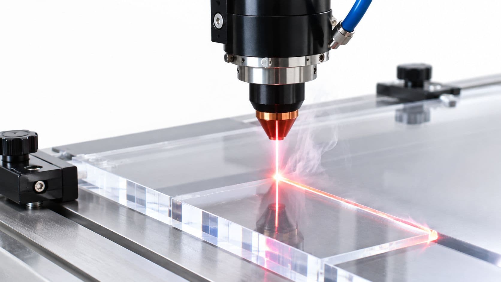
A CO₂ laser is generally the best laser to cut plastic because common polymers absorb its 10.6 µm wavelength well. Before cutting, confirm the resin identity and verify that the resulting edge is suitable for the part's actual function.
The popular advice usually starts with a safe plastic list and ends with a machine recommendation. That's backwards. The difficult question isn't whether a beam can pass through a sheet. It's whether the material is correctly identified, whether the process can be controlled without unacceptable emissions, and whether the finished edge will work in the assembly.
A clean-looking acrylic cut may be excellent for a flat prototype and unsuitable for a seal, snap-fit, optical surface, or repeatedly cycled mechanism. Treat material verification and functional edge validation as the two decision gates, then choose the laser, parameters, or alternative process around them.
Table of Contents
- Choosing the Right Laser Type for Plastics
Wavelength comes before power
Emissions remain part of machine selection
CO₂ Versus Ultrafast Laser Cutting for Thin Films- Match the process to the failure mode
Setting Power, Speed, and Assist Gas for PMMA- Build a small parameter matrix
Identifying Unknown Plastics Before Laser Cutting- Use a verification chain
Validating Edge Quality for Seals, Snap-Fits, and Optical Parts- Test the feature, not just the coupon
When to Use a Contract Manufacturer for Precision Prototyping- Look for process breadth, not just laser access
Choosing the Right Laser Type for Plastics
Laser cutting plastic is not a matter of buying more wattage. The polymer's chemistry determines how efficiently it absorbs the beam, while thickness, focus, beam quality, feed speed, and heat removal determine whether that absorbed energy produces a controlled cut or a melted channel.
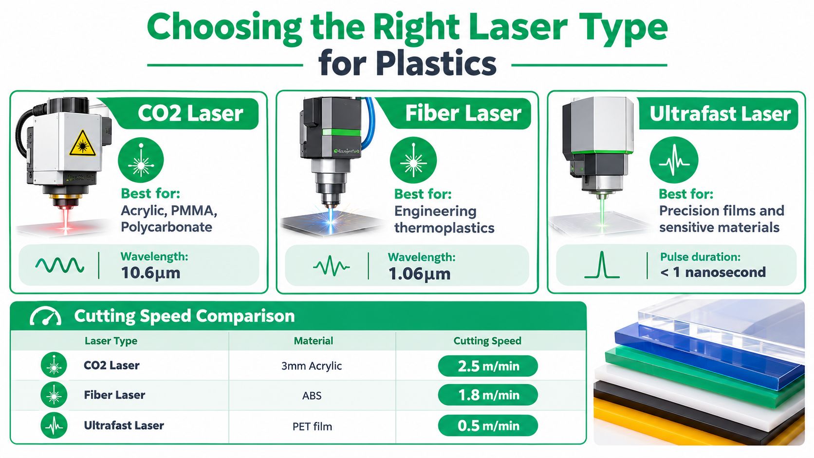
CO₂ lasers became foundational in polymer processing because common plastics absorb long-infrared energy far more effectively than shorter-wavelength industrial lasers. A peer-reviewed comparison of polyethylene, polypropylene, and polycarbonate sheets found high surface absorption around the typical 10.6 µm CO₂ wavelength, while the same materials remained comparatively transparent near the 1.6 µm wavelength associated with Nd:YAG lasers. That wavelength-dependent behavior explains the historical preference for CO₂ systems in plastic cutting, engraving, and film processing. The peer-reviewed study on wavelength-dependent polymer absorption provides the relevant engineering basis.
Wavelength comes before power
A 500 W CO₂ laser can be sufficient for cutting several nonmetallic materials, including plastics, rubber, paper, textiles, wood, and ceramics, according to the same research. That figure is a capability reference, not a universal recipe. A lower-power system with suitable absorption and stable optics may outperform a higher-power system applied to a poorly matched resin or an uncontrolled thermal setup.
The practical selection logic looks like this:
| Laser Type | Best Thickness Range | Typical Application |
|---|---|---|
| CO₂ | Thin to moderately thick polymer sheet | Acrylic, polymer panels, engraving, and film processing |
| Ultrafast pulsed | Thin precision films | Low-HAZ features and heat-sensitive polymer work |
| Shorter-wavelength industrial laser | Material-specific applications | Use only after absorption and process trials confirm suitability |
Emissions remain part of machine selection
The laser type doesn't make an unidentified plastic safe. A NIOSH evaluation of a desktop cutter measured respirable particles, sub-half-micron particles, VOCs, and carbon monoxide across cardboard, wood, plastic, and glass at several electrical currents, with and without exhaust ventilation. Plastic produced intermediate particle levels under those test conditions but high VOC levels, and emissions changed with the interaction of material, operating current, and ventilation. The NIOSH laser-cutter emissions study shows why extraction and approved materials belong in the process specification.
For prototype work, the relevant benchmark includes 2 to 10 mm sheets of PE, PP, and PC, but that range doesn't remove the need for trials. Polymer grade, pigment, additives, thickness, focus, and heat management can change edge melting, taper, discoloration, and the heat-affected zone.
Practical rule: Select the wavelength for the resin first, then qualify power and speed against the edge and emissions requirements. Nominal laser power alone doesn't establish manufacturability.
CO₂ Versus Ultrafast Laser Cutting for Thin Films
For thin films, the main competition isn't always between a low-power and high-power CO₂ system. It's often between a conventional thermal process and an ultrafast pulsed process that removes material with far less cumulative heat.
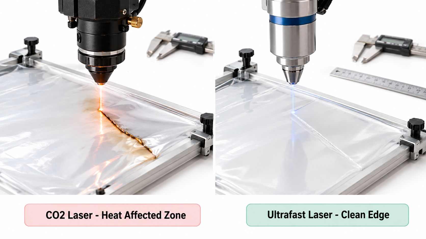
A comparative study on polymer films reported that 5 mil polyimide could be cut at speeds above 307 mm/s, with a 58 µm kerf and negligible HAZ. PET reached an effective 363 mm/s, with a 55 µm kerf and an approximately 10 µm HAZ. These results are benchmarks from a specific process, not settings to transfer blindly to another machine or resin. The comparative ultrafast polymer-film process study documents the relationship between pulse conditions, kerf, speed, and thermal damage.
Match the process to the failure mode
A CO₂ laser remains attractive when the film or sheet can tolerate a thermal edge and the priority is efficient cutting of broader flat geometry. It becomes less attractive when a narrow HAZ, minimal burr, low dimensional drift, or low debris load matters more than bulk throughput.
Ultrafast processing can change the trade-off because pulse duration and wavelength affect ablation behavior as much as average power. In the cited comparison, a 42 W green femtosecond source produced similar cutting speeds to a 70 W infrared beam, showing why power ratings can't be compared without considering wavelength, pulse duration, overlap, and the number of passes.
The correct qualification sequence is process-oriented:
- Establish the ablation threshold on a sacrificial coupon rather than starting with a production part.
- Sweep pulse overlap, repetition rate, scan speed, and pass count while measuring kerf, burr, HAZ, and debris.
- Check cumulative heat, because excessive overlap can raise thermal loading while insufficient overlap can leave bridges and produce dimensional scatter.
- Fixture the film flat, without stretching or distorting it, then inspect the released part rather than only the clamped condition.
Reinforced plastics need their own treatment. Research on carbon-fiber-reinforced polymer found fiber damage below 100 µm at cutting speeds of 2.5 m/min and above, while also identifying stand-off, pass count, nozzle diameter, and cooling gas as important variables. The result is a useful warning: composite behavior depends on both the matrix and the reinforcement, so a recipe for an unfilled film is not a reliable starting point for a reinforced laminate.
For any film process, extraction must match the resin, and PVC or unknown halogenated materials should be quarantined. Chemical compatibility is a prerequisite, not a finishing detail.
Setting Power, Speed, and Assist Gas for PMMA
PMMA rewards disciplined parameter development. It can produce a visually polished edge, but that appearance can hide taper, excessive kerf, redeposited melt, or a heat-affected zone that causes problems in assembly.
Start by confirming the PMMA grade, sheet thickness, pigment, protective film, and surface condition. Then lock the variables that should not change during the first screen. Keep nozzle standoff and focal position constant while varying power and feed rate. This prevents the initial test from mixing too many effects and makes the response easier to interpret.
Build a small parameter matrix
A published CO₂-laser PMMA study used a 27-run full-factorial design that varied assist-gas pressure, sheet thickness, cutting speed, and laser power. Its tested values included 7, 8, and 9 mm standoff, 8, 13, and 18 mm/s cutting speed, and 82.5, 90, and 97.5 W power. The reported combination for near-zero kerf angle was 7 mm standoff, 8 mm/s, and 97.5 W. The published PMMA parameter study gives those values as a process benchmark.
Use that benchmark to frame a screening plan, not to copy a universal recipe. Resin grade, moisture, optics, sheet thickness, enclosure airflow, and actual delivered power can all move the optimum.
Measure the responses that matter:
- Kerf width: Check both the top and bottom of the cut where access allows.
- Taper: Compare entry and exit dimensions, especially on mating features.
- HAZ: Look for softened, whitened, crazed, or visibly altered material beside the cut.
- Dross and redeposition: Inspect the underside and internal corners, not just the presentation face.
- Edge roughness: A polished appearance doesn't prove uniform geometry.
- Odor and fume behavior: Record observations under the actual extraction setup.
Validate the selected window
After identifying a promising region, adjust assist-gas pressure and focal position while keeping the other variables controlled. Excessive energy density commonly enlarges the HAZ, increases melt redeposition, and worsens taper. Insufficient energy leaves incomplete cuts or small uncut bridges.
Run at least five production-representative parts after optimization, using the intended material lot, protective film, geometry, and machine configuration. Inspect entry and exit edges, record actual delivered power rather than commanded power, and cross-section a thick or safety-critical part destructively.
An acceptance plan should combine dimensional capability, edge condition, odor and fume assessment, and functional assembly. If the part is a snap, gasket, optical carrier, or structural interface, test that feature directly. A straight-line coupon can confirm that the beam cuts. It can't confirm that the product works.
Identifying Unknown Plastics Before Laser Cutting
The most dangerous material on a laser bed is not necessarily the plastic on a published “do not cut” list. It's the sheet nobody can identify.
Unpainted stock from a known supplier is relatively easy to control. Painted, laminated, recycled, imported, or mislabeled sheet is different. Surface appearance tells you little about the base resin, additives, adhesive layers, flame retardants, or halogen content.
Use a verification chain
Treat material identity as a release decision. Ask the supplier for a certificate or technical data, inspect the resin marking where one exists, and review the relevant SDS. If the documentation conflicts with the physical sheet, stop the laser trial rather than treating the discrepancy as an inconvenience.
A practical verification workflow is:
- Check supplier documentation: Confirm resin family, grade, additives, thickness, and any laminate or coating.
- Inspect markings: Look for molded or printed resin identification, but don't treat a missing mark as evidence of safety.
- Review the SDS: Look for decomposition hazards, halogen content, corrosivity, and ventilation requirements.
- Separate coatings from substrate: Paint, adhesive, protective film, and decorative laminate may change the emissions profile.
- Use a small non-laser sample: A controlled mechanical test can reveal layers, brittleness, or construction without exposing the machine to an unknown thermal decomposition.
- Use portable identification technology where available: Material screening can support documentation, but it shouldn't replace supplier traceability and engineering judgment.
Research on thermal processing reports that laser cutting can generate more hazardous substances than ordinary thermoforming, with PVC presenting particularly high potential for benzene and hydrogen chloride emissions. The occupational exposure research on laser processing plastics is especially relevant when a team is tempted to use ventilation as a universal control.
Know what an enclosure does not solve
An enclosed Class 1 machine controls laser radiation access. It does not certify the chemical compatibility of the workpiece. Hydrogen chloride can corrode internal components rapidly, and particulate or carbon filtration may not neutralize corrosive acid gases.
An enclosure protects against the beam. It doesn't turn an unidentified plastic into an approved material.
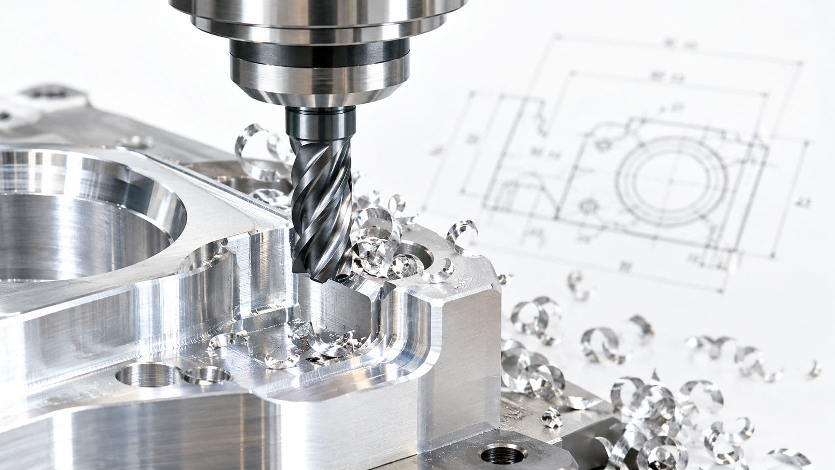
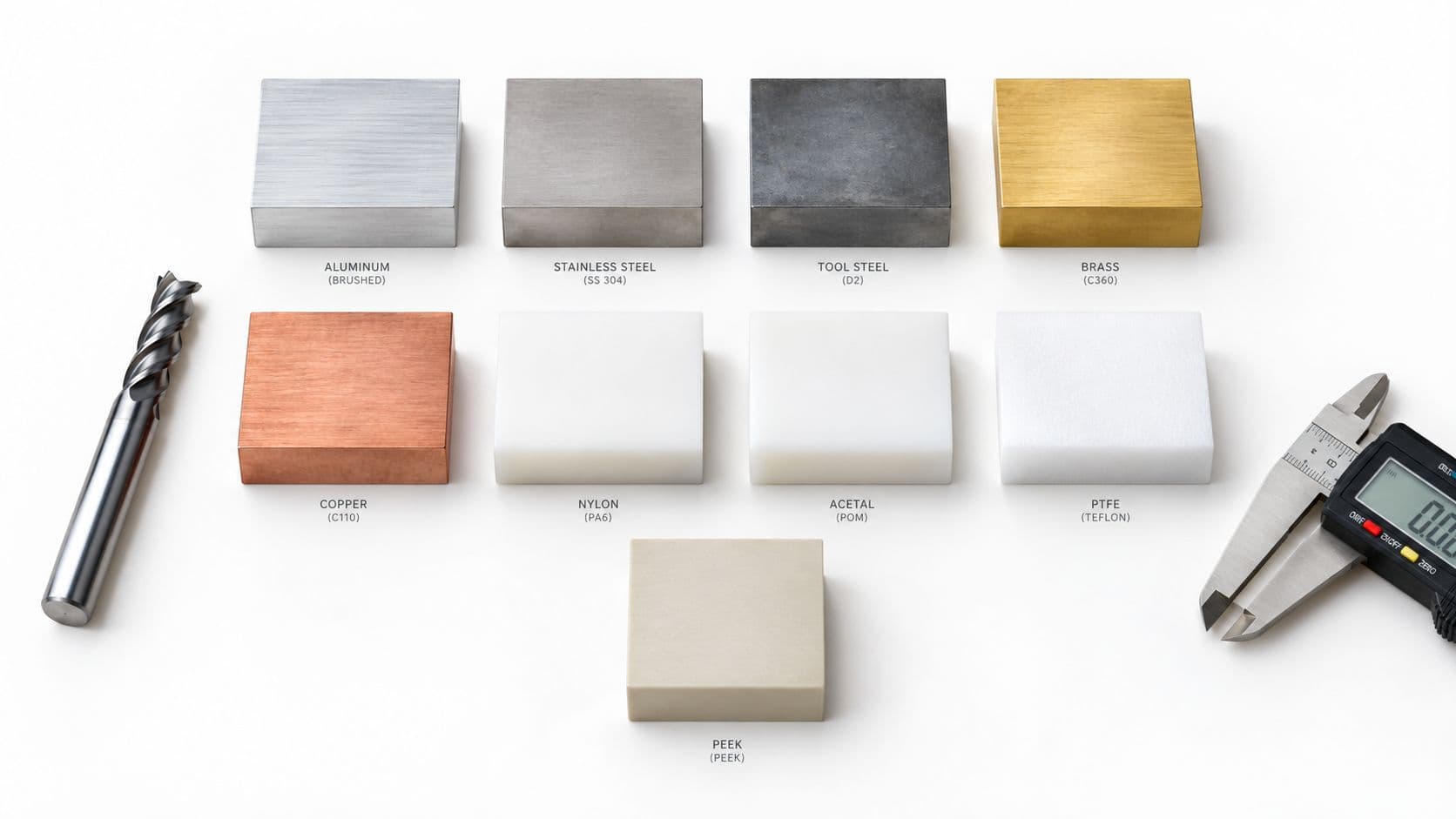
If the resin is unknown, documentation is incomplete, or halogenated content is possible, route the job to CNC routing, knife cutting, waterjet cutting, or another non-thermal process after confirming that the alternative is suitable. For material-selection guidance on mechanical processing options, use this CNC machining materials reference.
That decision may cost more per part than a trial cut, but it protects the machine, operators, and development schedule. A failed edge can be reworked. Corrosive contamination and an undocumented exposure event are harder to unwind.
Validating Edge Quality for Seals, Snap-Fits, and Optical Parts
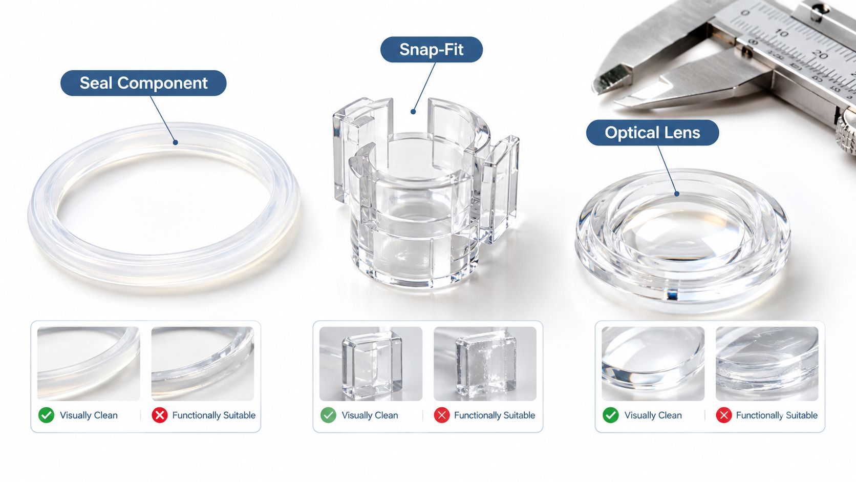
A laser-cut edge can look excellent and still fail functionally. Appearance inspection is useful for cosmetic parts, but it is not enough for interfaces that seal, flex, locate, transmit light, or carry repeated load.
Laser parameters jointly affect top and bottom kerf width, focal position, feed rate, HAZ size, and cut-wall roughness. The resulting edge may have localized thermal damage, taper, redeposited material, residual stress, or dimensional drift that only appears during assembly or cycling.
Test the feature, not just the coupon
For a seal, inspect the actual sealing land and measure whether the edge remains uniform around corners. For a snap-fit, check insertion force, retention, root condition, and repeated engagement. For an optical part, inspect haze, edge chipping, contamination, and any distortion near the light path.
Use the intended:
- Resin grade and color
- Sheet thickness
- Protective film and surface finish
- Feature geometry
- Power, speed, focus, gas, and extraction settings
- Production inspection method
A visually clear acrylic edge may still be unsuitable where taper changes interference, where redeposited material affects a seal, or where thermal stress initiates cracking. The process should be judged against the assembly's failure modes, not the operator's first visual impression.
Choose the process around the tolerance risk
Laser cutting is often a strong choice for rapid flat prototypes, intricate profiles, labels, panels, and low-volume parts where a thermal edge is acceptable. It becomes a weaker choice when the design requires low residual stress, tightly controlled edge geometry, thick opaque engineering plastic, or repeatable tolerance across a difficult material lot.
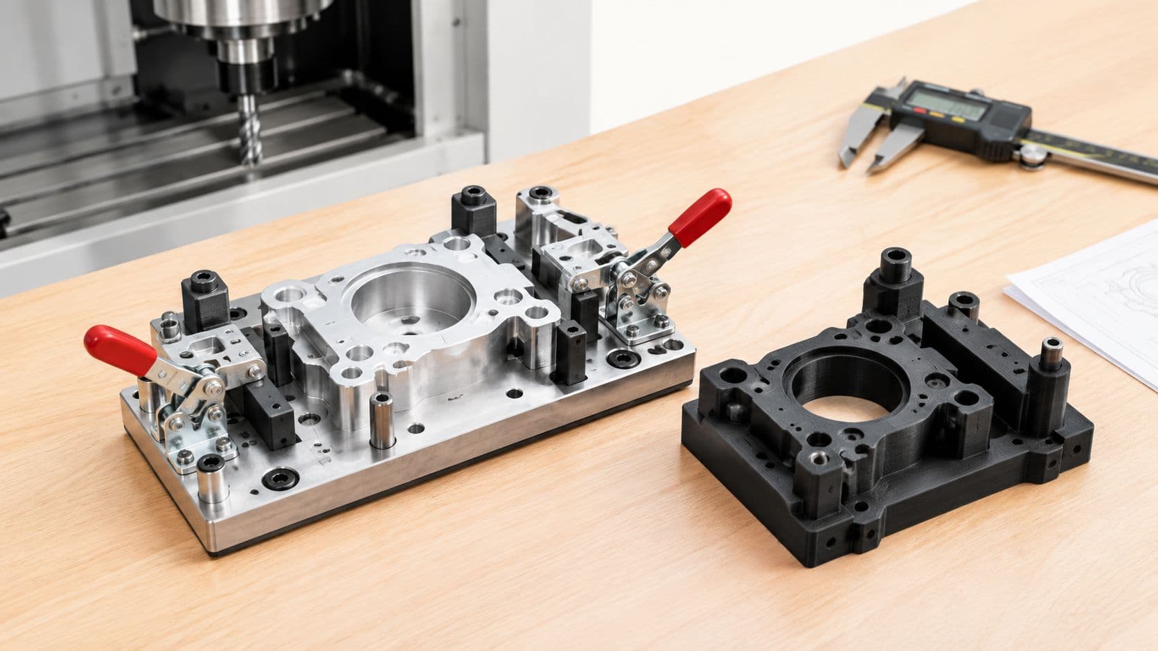
Consider CNC machining when the part needs controlled walls, bores, pockets, or a low-heat edge. Molding becomes more appropriate when the geometry and volume justify tooling and the production material must match the final product. Waterjet cutting can help where thermal damage is unacceptable, while additive manufacturing may suit a geometry that doesn't depend on flat-sheet behavior.
The precision laser cutting guidance is useful as a starting point, but the release decision should come from feature-level inspection. Measure the part, assemble it, cycle it where relevant, and record the failure mode if it doesn't meet requirements.
A clean edge is a process result. A reliable seal, snap, or optical interface is a product result.
When to Use a Contract Manufacturer for Precision Prototyping
Keep laser cutting in-house when the material is approved, the geometry is flat, the edge requirements are modest, and the team can control extraction and inspection. A benchtop or production laser is efficient for quick design loops when the part does not need secondary machining, molding, or specialized finishing.
Escalate to a contract manufacturer when the prototype has multiple manufacturing processes, demanding functional features, or a tolerance target that a single laser operation cannot hold consistently. The same applies when the material is difficult to identify, when the design needs a matched cosmetic finish, or when repeated internal trials would put equipment and schedule at risk.
Look for process breadth, not just laser access
A capable manufacturing partner should help select the process rather than accept every drawing as a laser-cut job. Useful capabilities may include CNC milling and turning, 3D printing, sheet metal fabrication, injection molding, vacuum casting, and surface finishing. That breadth matters when the prototype evolves from a flat profile into a housing, mechanism, overmolded assembly, or low-volume production part.
Ask practical questions before sending the design:
- Material control: Can the supplier verify resin, grade, additives, and lot traceability?
- Process choice: Will the team recommend CNC, molding, waterjet, additive manufacturing, or laser cutting when appropriate?
- Inspection: Will they measure kerf, taper, HAZ, critical dimensions, and functional interfaces?
- Finishing: Can they provide a controlled cosmetic and functional finish without several disconnected handoffs?
- Iteration: Can they support design changes from feasibility through pilot parts?
- Documentation: Will they provide inspection records and clearly identify deviations?
A Shenzhen-based partner such as FIRMFG can be relevant when an engineering team needs one workflow spanning CNC machining, 3D printing, sheet metal fabrication, injection molding, vacuum casting, and surface finishing. Its role should be evaluated on technical feedback, process selection, inspection discipline, and communication, not on the presence of a laser alone.
Use outsourcing to reduce process uncertainty
The value of a contract manufacturer appears when the team needs to compare processes quickly. A supplier that supports rapid prototyping services can help move from a laser-cut concept to a machined, molded, cast, or printed version without restarting the supplier search for every iteration.
Send a complete package: CAD files, resin and grade, thickness, protective-film requirements, critical dimensions, functional loads, assembly context, cosmetic expectations, and any prohibited processes. Ask for a first-article plan that tests the actual feature, not only a representative straight cut.
The best decision is not always “find the fastest laser.” It's “choose the process that gives the product team trustworthy evidence.” When material identity, edge function, and downstream assembly all matter, a manufacturing partner can reduce the risk of optimizing the wrong process.
FIRMFG helps engineering teams validate plastic designs through CNC machining, laser cutting, 3D printing, molding, casting, finishing, and low-volume production support. Share your resin, geometry, tolerance targets, and functional requirements with FIRMFG to get process guidance and a practical path from prototype to production.