Rapid Prototyping Services: An Engineer's Guide
The most popular advice about rapid prototyping services is also the least useful: choose the supplier that can ship a part fastest. A part that arrives tomorrow can still teach you almost nothing if it uses the wrong material, misses the critical tolerance, or cannot reproduce the loads and interfaces your product will face.
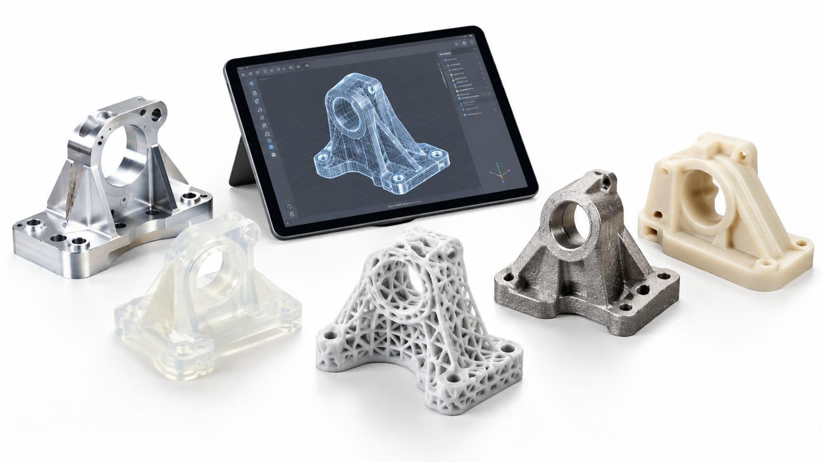
The better question is, which process mix produces the fastest reliable learning while reducing rework and certification risk? A cosmetic SLA model, a machined metal bracket, an SLS nylon manifold, and a polyurethane casting may all represent the same CAD design, yet each answers a different engineering question. Treating them as interchangeable is how hardware teams create false confidence.
Rapid prototyping has also moved well beyond visual models. The market is shifting toward functional components tested for fit, performance, assembly, and operating conditions, with providers combining additive manufacturing, CNC machining, vacuum casting, and post-processing across the development cycle, as described in recent rapid prototyping service market coverage. The practical challenge is deciding how much prototype fidelity your next decision requires.
Table of Contents
Comparing Core Manufacturing Processes- Process Selection Matrix for Functional Prototypes
The Reality of Dimensional Accuracy and Tolerances- Read tolerance as a system
Material Selection and Surface Finishing Workflows- Choose the material around the test
The True Economics of Iteration and Rework- Calculate total iteration cost
Scaling from Feasibility to Low-Volume Production- Preserve design intent through process changes
Evaluating Quality Systems and Manufacturing Partners- Ask for evidence, not assurances
Rethinking Speed in Hardware Iteration
A 24-hour turnaround helps with enclosure layout, connector position, or basic ergonomic form. It can be the wrong optimization for a part that carries load, retains a seal, survives repeated assembly, or holds a tolerance tied to certification. In those cases, speed only shortens the time to an irrelevant result.
State the prototype's purpose in every request for quote. An appearance model evaluates shape, styling, color, and user interaction. A functional prototype evaluates fit, strength, thermal behavior, assembly sequence, surface contact, and operation under representative conditions. Those goals may require different materials, processes, inspection methods, and test fixtures.
Practical rule: Choose the prototype that removes the largest current engineering uncertainty, not the one with the shortest advertised lead time.
Market coverage from Straits Research's rapid prototyping service market coverage notes that individual printed parts can ship in one to three days, while a complete functional prototype may take three to six weeks. The longer schedule includes design revisions, integration, testing, and process decisions. A printed housing may arrive quickly, yet the integrated assembly can still require several build methods and test loops.
Match prototype depth to risk
Write down the decision the part must support before selecting a process. For a motor bracket, a quick polymer print can answer whether the geometry fits around the motor. It cannot establish whether the bracket maintains alignment under operating load. That question requires a production-relevant material, controlled machining or printing, inspection, and a fixture that reproduces the final interface.
A practical sequence is:
- Concept screening: Use a fast additive process to verify packaging, basic form, and access.
- Interface validation: Add machined features or post-machining where mating surfaces, holes, and bearing seats control assembly.
- Functional testing: Select a material and process that reproduce the relevant mechanical and environmental behavior.
- Pre-production learning: Use the likely production process, or a credible bridge process, to expose DFM and assembly risks.
Material mismatch can turn an apparently successful test into expensive rework. A resin prototype may pass a quick fit check, then fail a seal test because it creeps, cracks, or changes dimension under compression. Repeating that test with machined aluminum may cost more and take longer initially, but it produces evidence closer to the hardware's real load path and sealing behavior.
A cosmetically perfect model can hide weak layer adhesion, resin brittleness, warped interfaces, or unsupported internal features. A rough machined prototype may look unfinished while providing the data needed to approve alignment or load transfer. The useful measure of speed is how quickly the team reaches a defensible design decision, not how quickly a parcel arrives.
Comparing Core Manufacturing Processes
No single fabrication method dominates every prototype stage. CNC machining removes material from a solid block, so it's often the right choice for metal brackets, bearing interfaces, heat-transfer components, and parts whose strength must come from a known production material. Three-axis machining handles many prismatic parts, while four-axis and five-axis work can reduce setups and reach complex surfaces. The trade-off is programming, fixturing, tool access, and higher setup effort than a basic printed build.
Additive manufacturing wins when geometry is complex, internal channels are difficult to reach, or the team needs several design variants without tooling. SLA uses photopolymerization for smooth surfaces and fine detail, but many standard resins are poor substitutes for production thermoplastics under sustained mechanical or thermal stress. SLS fuses polymer powder without conventional support structures, making it useful for nested parts, complex nylon components, and internal passages. FDM is economical for concept models, larger fixtures, and selected functional thermoplastics, but layer direction, surface texture, and anisotropy need to be considered during testing. Metal additive processes can produce geometries that are difficult to machine, though they bring their own requirements for build orientation, support removal, heat treatment, and inspection.
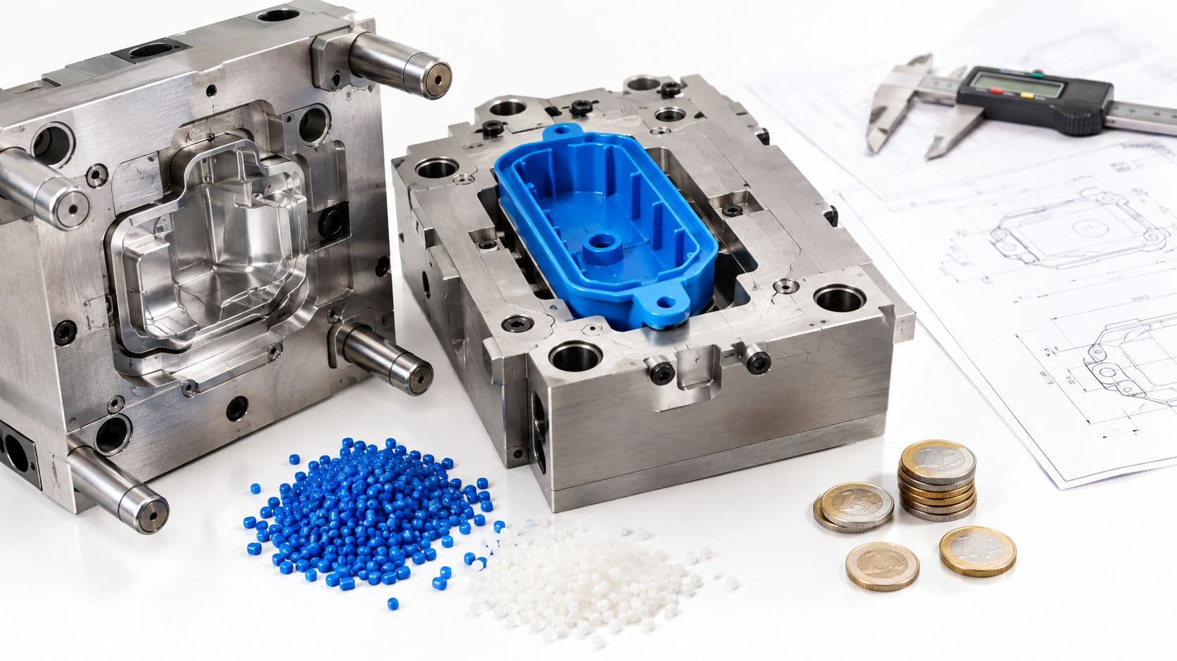
Vacuum casting sits between one-off additive parts and molded production parts. A master pattern creates a silicone mold, then polyurethane resin reproduces parts with a molded appearance and useful short-run flexibility. It makes sense when you need several visually consistent units, an elastomeric option, or a bridge build before committing to injection tooling. It's not the right substitute for every production material, and mold life, shrinkage, parting lines, and resin choice must be part of the design review.
For a direct discussion of geometry, tolerance, strength, and cost trade-offs, see this CNC machining versus 3D printing comparison.
Process Selection Matrix for Functional Prototypes
| Process | Best For | Tolerance Reality | Ideal Application |
|---|---|---|---|
| CNC machining | Metal and engineering-plastic parts requiring controlled interfaces | Strong dimensional control, but dependent on material, tooling, setup, and inspection | Brackets, bearing seats, heat sinks, structural components |
| SLA | Fine detail, smooth surfaces, visual and fit validation | Process and resin dependent, with functional limits under load | Enclosures, styling models, small detailed components |
| SLS | Complex polymer geometry and unsupported internal features | Good for functional geometry, but dependent on orientation, powder condition, and post-processing | Nylon manifolds, ducting, lattice structures, snap-fit studies |
| FDM | Economical concept models, fixtures, and selected thermoplastics | Layer direction and build parameters strongly affect results | Large packaging models, assembly aids, early functional checks |
| Metal 3D printing | Complex metal geometry and difficult-to-machine internal features | Requires control of build strategy, finishing, and inspection | Lightweight structures, complex brackets, specialized metal parts |
| Vacuum casting | Small batches, appearance fidelity, and bridge builds | Master pattern and mold condition influence repeatability | Market samples, molded-look housings, low-volume validation |
The decision should begin with the test, not the machine catalogue. If a component must retain a press fit, choose a process that can hold and verify that interface. If it must reproduce an internal flow path, prioritize geometric freedom and inspectability. If the team needs multiple consistent samples for assembly review, casting may be more efficient than repeatedly printing and finishing individual parts.
The Reality of Dimensional Accuracy and Tolerances
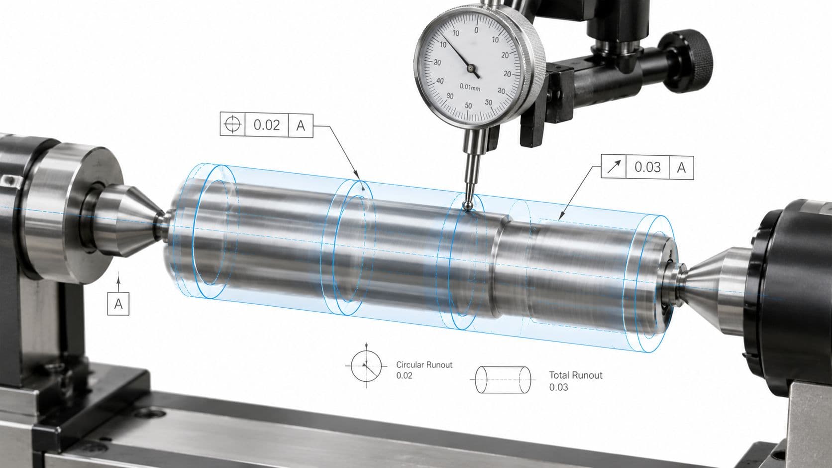
Your CAD model has perfect nominal geometry. The manufactured part inherits variation from the process, material, orientation, machine calibration, thermal history, supports, finishing, and measurement method. A drawing tolerance without a process and inspection plan is only an intention.
A 2021 quality-control review found that, in most polymer additive cases, dimensional accuracy doesn't exceed ±0.05 mm, and it emphasized a verification chain that runs from CAD validation through post-processing and metrology. The review is available in this peer-reviewed quality-control study of additive manufacturing accuracy. That finding doesn't mean every feature will miss its target. It means tolerance-critical features need deliberate process selection rather than assumptions based on nominal printer resolution.
Read tolerance as a system
A hole may measure correctly before finishing and become undersized after coating. A flat sealing face may pass a point measurement but fail because of overall form error. A printed enclosure can match external dimensions while its bosses shift enough to create assembly stress. These are functional failures, not cosmetic defects.
Before releasing a prototype drawing, separate features into three groups:
- Critical interfaces: Bearing seats, sealing faces, locating pins, connector openings, and mounting holes need defined datums and inspection.
- Functional but forgiving surfaces: These can accept broader variation if clearance, movement, or load transfer remains unaffected.
- Cosmetic surfaces: These need appearance standards, but shouldn't receive expensive precision machining unless the product function depends on them.
The comparison between SLA and SLS also shows why a process label alone isn't enough. One study reported median trueness RMS values of 0.148 mm for SLA and 0.144 mm for SLS, while precision RMS values were 0.117 mm for SLA and 0.096 mm for SLS, with the result depending on the guide and splint geometries evaluated. The figures appear in this comparative study of SLA and SLS geometric performance. SLS delivered better precision in some geometries even though average trueness was similar.
Build the verification chain before fabrication
Ask the supplier how it will validate the part, not merely how it will manufacture it. The chain should cover the CAD revision, drawing interpretation, process parameters, support strategy, finishing allowance, datum scheme, and final measurement. For a tight-tolerance metal component, a coordinate measuring machine or equivalent metrology may be appropriate. For a flexible polymer part, the inspection fixture and measurement force can influence the result.
A practical drawing should identify what matters. Over-tolerancing every feature raises cost and can force unnecessary machining or finishing. Under-specifying a critical interface allows a part to pass a superficial inspection and fail during integration. Functional tolerances should reflect the test method, assembly clearance, material behavior, and expected production route.
Material Selection and Surface Finishing Workflows
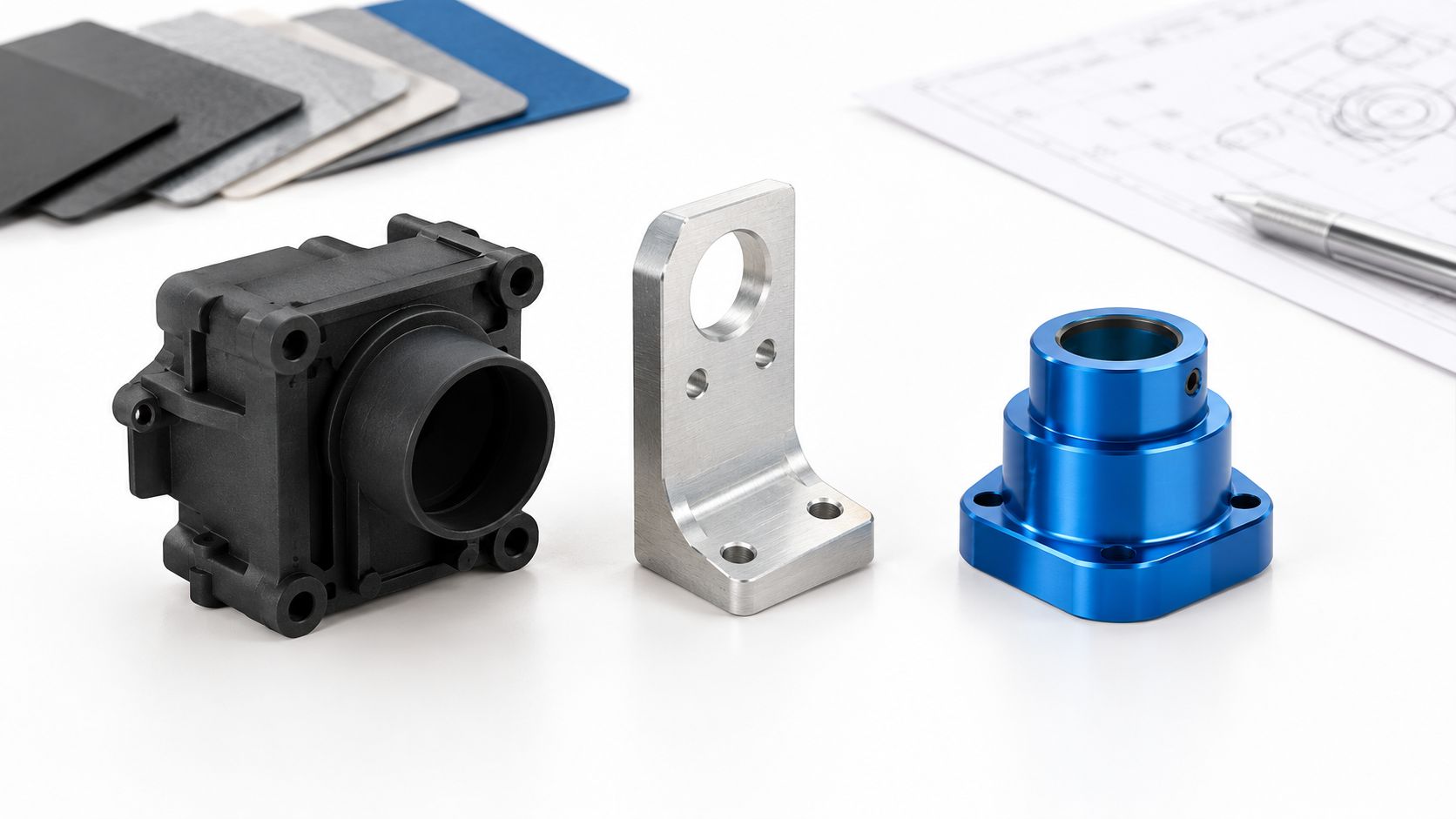
A prototype material isn't just a color and a line item on a quote. It determines how the part bends, wears, heats, seals, threads, grips, and responds to repeated assembly. A resin model may confirm the location of a button, while an aluminum prototype may be necessary to validate heat flow, stiffness, or threaded inserts.
Choose the material around the test
Start with the failure mode you're trying to observe. If the part must withstand impact, use a material and process that represent impact behavior. If it carries a sustained load, account for creep and temperature. If it contacts a chemical, lubricant, human body, or sealing surface, confirm compatibility rather than relying on a similar-looking resin.
For a metal prototype, the alloy, temper, heat treatment, and surface condition can all affect the result. For polymer builds, note whether the material is isotropic, moisture-sensitive, UV-sensitive, or vulnerable to heat. If the production part will be injection molded, a printed approximation may validate packaging but not necessarily snap-fit durability, weld-line behavior, or long-term deformation.
Treat finishing as part of the design
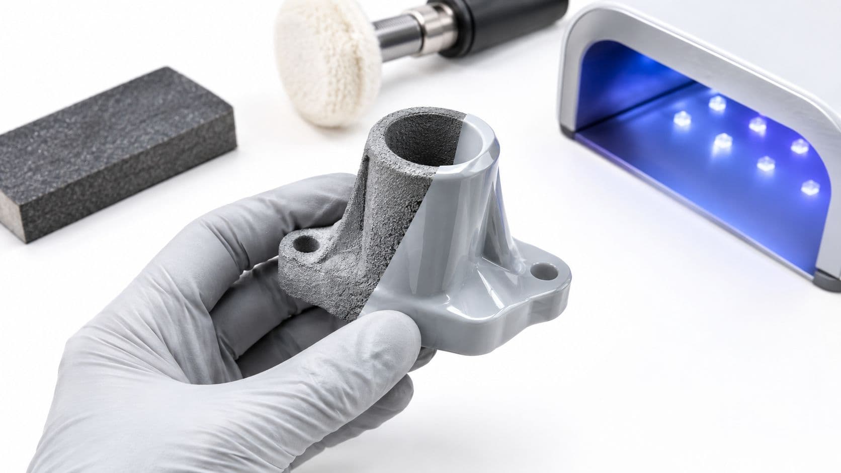
Post-processing changes dimensions and surface behavior. Anodizing can add corrosion resistance and a controlled appearance to aluminum, but the treated layer must be considered around close fits. Passivation supports corrosion resistance for stainless steel without applying a decorative coating. Bead blasting creates a uniform matte texture, while sanding and polishing can improve appearance and alter edge sharpness. Powder coating and plating add their own thickness, masking, and adhesion requirements.
A finish can also affect friction, fatigue initiation, electrical contact, and sealing. A rough printed surface may damage an elastomer seal. A coated hole may no longer accept a fastener. A polished surface may look excellent but conceal a geometry problem if the supplier removes too much material during hand finishing.
For a practical overview of how finishing changes printed parts, review this guide to 3D printing post-processing methods.
Specify the complete workflow
Your request should state the as-built condition, required finish, masking areas, critical dimensions after finishing, and cosmetic acceptance criteria. Include whether the supplier should assemble inserts, bond components, or deliver parts individually. If the prototype will transition to low-volume molding, ask how the proposed finish compares with the intended molded texture and whether the master pattern needs specific preparation.
A good supplier flags finish-related risks before production. That conversation is more valuable than discovering after delivery that a coated mating surface no longer fits, or that a polished face has lost the flatness required for sealing.
The True Economics of Iteration and Rework
The quoted price of a prototype part is rarely the cost that matters. The program pays for design review, setup, material, finishing, inspection, shipping, engineering time, test fixtures, failed builds, and the delay created when one part holds up an entire assembly. A low unit price can be expensive if it produces ambiguous test results.
Independent market data places the U.S. 3D printing and rapid prototyping services market at about $4.0 billion in 2026, while also highlighting that design revisions and tooling choices can extend both schedule and budget. See the IBISWorld market data for U.S. 3D printing and rapid prototyping services. The market size doesn't tell you what your part should cost. It does show why buyers need a better cost model than a single instant quote.
Calculate total iteration cost
For each prototype loop, ask:
- What decision will this part support? If the answer is unclear, the build may be premature.
- Which features must be production-representative? Machine those features even if the rest of the body is printed.
- What happens if the part fails? Include redesign, repeat inspection, retesting, and schedule impact.
- Will the process survive the next build? A cheap method that cannot reproduce the required feature creates repeated uncertainty.
- Can one supplier manage the handoffs? Multiple vendors may introduce inconsistent finishes, datums, materials, and documentation.
A hybrid build often offers the strongest economics. Print a complex housing, machine the sealing face, use a metal insert at the load point, and finish only the surfaces users or testers will evaluate. This approach avoids paying for precision where it has no value, while protecting the interfaces that determine whether the test means anything.
Rework is a technical cost
Suppose a bracket fails because a printed hole is misaligned. Reprinting the bracket may be cheap, but the assembly test, technician time, teardown, and schedule interruption aren't free. If the same hole is critical to alignment, machining it from metal at the outset may reduce total program cost even when its quoted unit price is higher.
Procurement should therefore compare process mixes, not isolated part prices. A useful RFQ describes the intended test, critical dimensions, material target, finish, quantity, inspection requirement, and deadline. The supplier can then suggest where additive manufacturing, CNC machining, sheet metal, casting, or tooling should be combined.
Scaling from Feasibility to Low-Volume Production
The transition from one prototype to a pilot build usually exposes the gaps that a one-off part can hide. A design may assemble once with hand fitting, yet fail when multiple parts must interchange. A printed cover may look correct, while the production-intent finish changes the fit around buttons, seals, and fasteners.
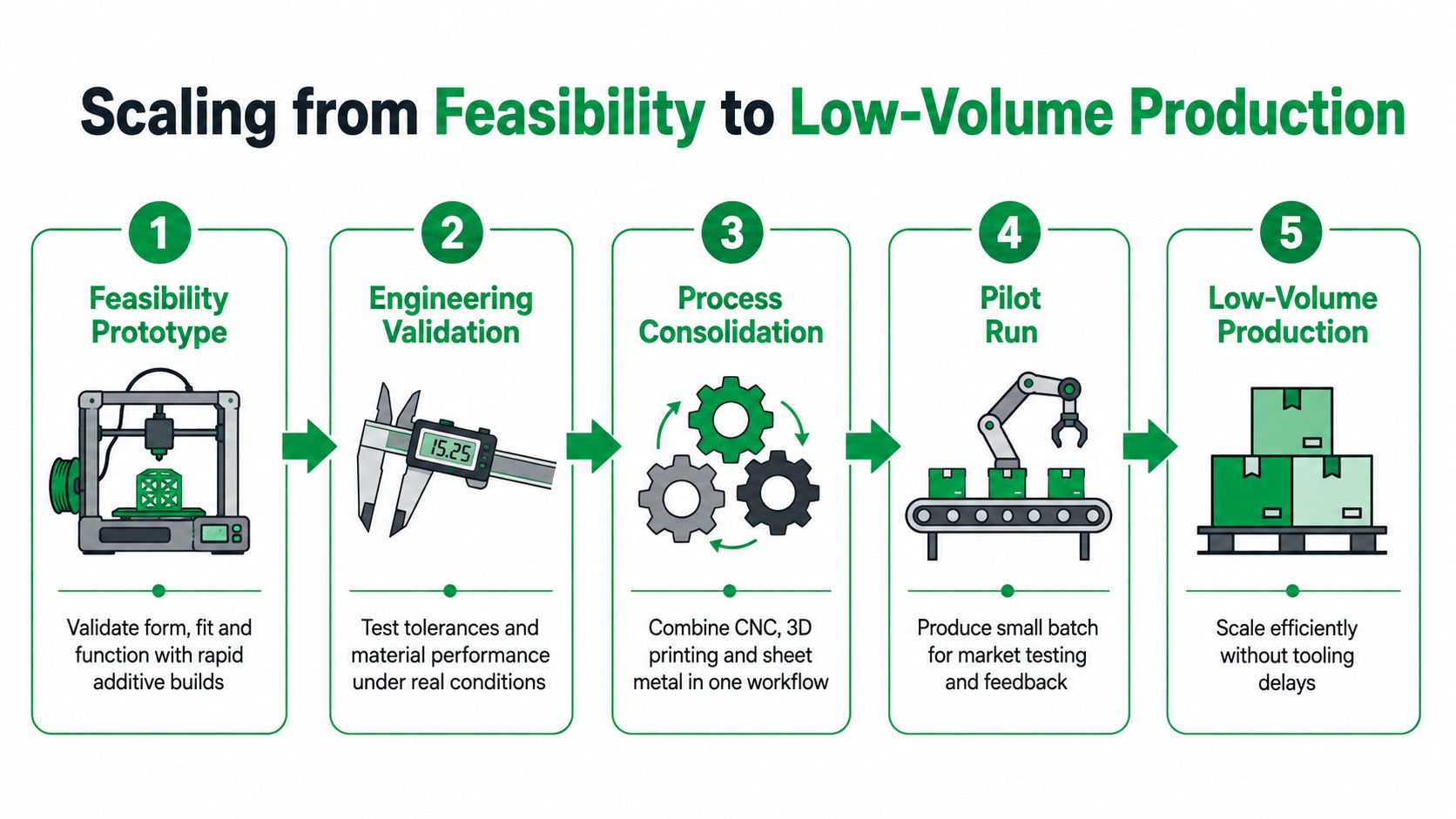
A capable manufacturing partner treats the prototype as an NPI activity, not an isolated fabrication order. The workflow begins with feasibility, moves through engineering validation, consolidates processes, and then prepares a controlled pilot run.
Preserve design intent through process changes
Consider a small electromechanical assembly with a machined aluminum frame, a printed duct, sheet metal brackets, and a molded-looking outer cover. Early feasibility may use fast additive parts to confirm envelope and access. Engineering validation then replaces the load-bearing frame with machined metal, checks bracket datums, and tests the duct geometry under representative flow conditions.
The important discipline is to document what changed and why. If the production route will use molding, the team should review draft, wall transitions, ribs, bosses, parting lines, and finish expectations before cutting tooling. If the pilot will use vacuum casting, the master pattern and silicone mold need their own inspection and acceptance criteria.
A consolidated partner can reduce friction between these operations. FIRMFG, for example, combines CNC machining, 3D printing, sheet metal fabrication, injection molding, vacuum casting, and surface finishing for prototype and low-volume workflows. That capability doesn't eliminate engineering review, but it can reduce the number of supplier handoffs where dimensions, finishes, and revision history are commonly lost.
Use each stage to answer a different question
The feasibility build should reveal whether the architecture can physically work. Engineering validation should establish whether the design survives its intended interfaces and conditions. Process consolidation should expose differences between prototype methods and the likely production route. The pilot run should verify assembly instructions, inspection points, supply continuity, and user feedback.
The rapid prototyping market is projected to grow from USD 4.83 billion in 2026 to USD 24.71 billion by 2035, with a projected 19.94% compound annual growth rate, according to this rapid prototyping market report. The report links that projected growth to investment in multi-process capacity and low-volume manufacturing options. For engineering teams, the practical implication is clear: service providers are increasingly expected to support more than a single printed part.
Don't approve a pilot solely because the first prototype looked right. Require evidence that critical dimensions are controlled, materials are documented, finishes are repeatable, and the supplier can manage the next revision without resetting the entire process.
Evaluating Quality Systems and Manufacturing Partners
A fast supplier that delivers nonconforming parts is slow in the only way that matters. Your team loses time inspecting, explaining, reworking, and repeating tests. The partner-selection process should therefore assess engineering judgment and quality infrastructure before you upload proprietary CAD.
Start with the part's risk profile. A consumer product enclosure may need cosmetic consistency and reliable assembly. A medical device component may require documented material and process controls. An automotive or aerospace part may require traceability, controlled revisions, and inspection records appropriate to its application. The supplier's capabilities should match those obligations.
Ask for evidence, not assurances
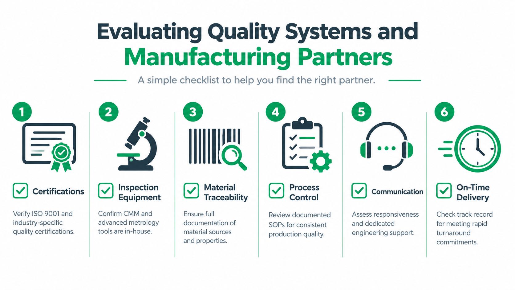
Use a structured review before committing to a build:
- Quality certifications: Verify the scope and validity of ISO 9001 or industry-specific certifications such as ISO 13485 where relevant.
- Inspection equipment: Confirm whether the supplier has suitable metrology, such as CMM capability, optical measurement, gauges, and calibrated inspection tools.
- Material traceability: Ask for material certificates, resin or alloy identification, batch records, and documented substitutions.
- Process control: Review how the supplier controls CAD revisions, work instructions, machine settings, finishing, and final release.
- Engineering communication: Test whether the team asks about function, loads, datums, finish, and test conditions before quoting.
- Delivery and recovery: Ask how the supplier handles a missed milestone, nonconforming part, urgent revision, and replacement shipment.
For a deeper checklist covering inspection, documentation, and manufacturing controls, use this resource on quality control in manufacturing.
Review the quote as an engineering document
A useful quote should identify the process, material, finish, quantity, inspection level, assumptions, and delivery conditions. If the supplier offers a price without asking what the part must do, the quote may be fast but technically incomplete.
Pay attention to DFM feedback. A meaningful review should flag inaccessible CNC features, unsupported additive geometry, thin walls, trapped volumes, unsuitable draft, finish buildup, and tolerance conflicts. It should also distinguish mandatory changes from optional cost reductions. That distinction helps your team protect design intent instead of accepting generic manufacturing advice.
Finally, evaluate support after delivery. Can the supplier provide inspection reports, material documentation, replacement handling, and a clear path to the next process? The right partner doesn't merely make the first part. It helps your team convert prototype evidence into a controlled decision about the next build.
FIRMFG supports functional prototyping and low-volume manufacturing through CNC machining, additive manufacturing, sheet metal, molding, vacuum casting, finishing, inspection, and DFM feedback. Share your CAD files and validation requirements with FIRMFG to discuss a process mix designed to reduce rework, control critical interfaces, and move your hardware program toward production.