Porosity in Castings: Types, Causes, Detection and Fixes
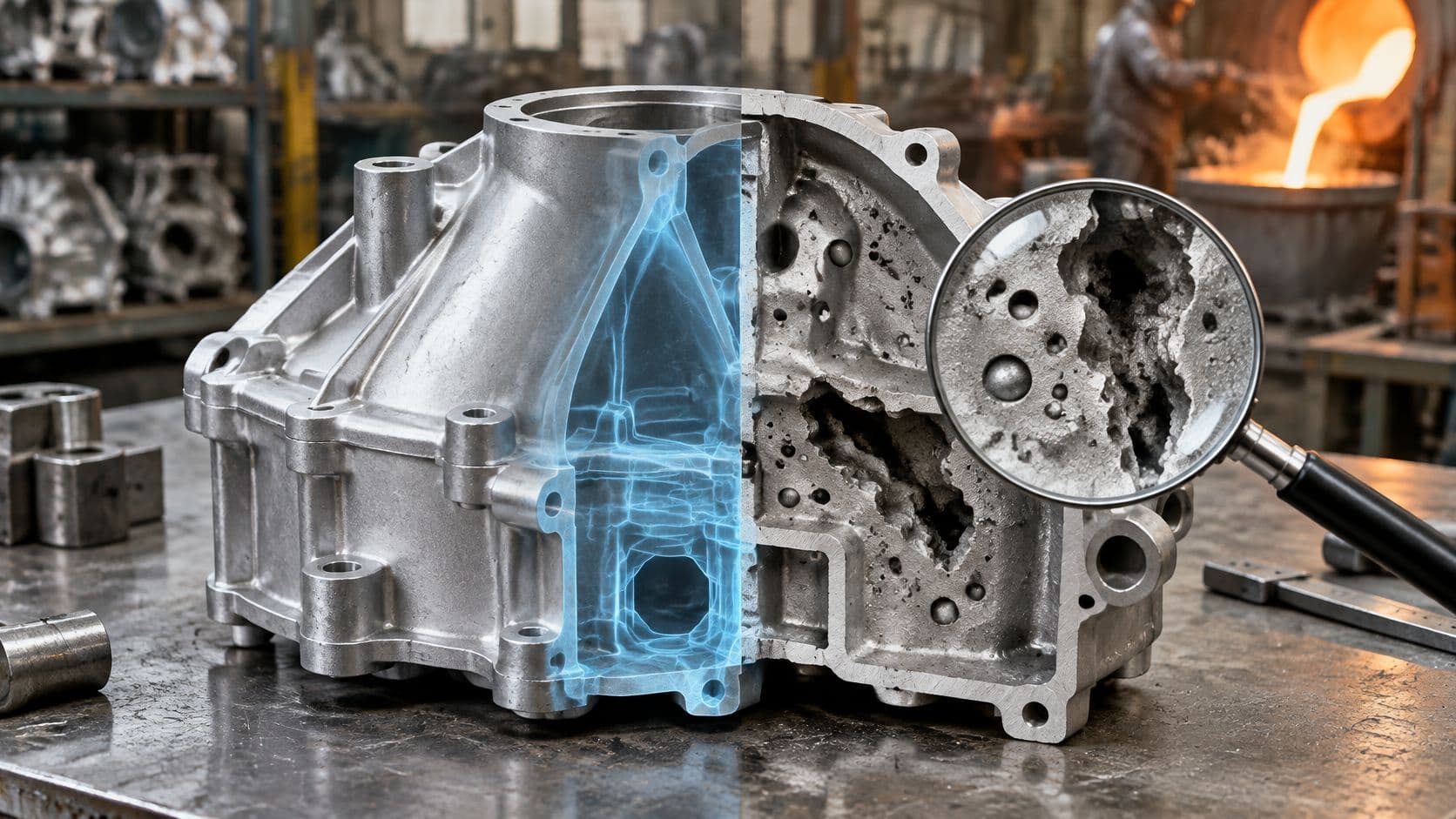
Porosity accounted for 64% of external defects in a Pareto review of internal and external foundry defects reported in a 2024 foundry study. That's a reason to treat porosity in castings as a design and manufacturing issue, not just a surface-quality concern. The useful question isn't just how much empty space a part contains. It's whether those voids interfere with what the part must do.
Table of Contents
Porosity Types in Castings at a Glance- Recognize the pattern before naming the cause
Gas and Shrinkage Causes Behind Each Pore- Separate dissolved gas from trapped air
Detection Methods and How to Choose One- Match the method to the failure mode
Tracing a Pore Back to Its Root Cause- Follow a repeatable diagnostic loop
Process and Material Controls That Prevent Porosity- Control the melt and the fill together
Remediation Options for Prototypes and Low-Volume Runs- Match the response to the defect
Confirm Your Inspection and Fix Path Before the Next Run
Why Porosity Decides Whether a Casting Works
A casting can have a clean surface and still fail after machining, assembly, or pressure testing. The outside tells you about the outside, not whether the metal beneath a sealing face or mounting boss is continuous.
Think of a cake that looks golden but collapses when sliced because its internal pockets weren't controlled. The analogy only goes so far, but it captures the inspection mistake: an acceptable skin doesn't prove an acceptable interior.
For a design engineer, the consequences depend on the feature involved. A pore near a lightly loaded cosmetic edge creates a different problem from a pore beside a highly stressed fillet. A connected pore path through a fluid housing creates another problem altogether.
Treat porosity as a functional risk
Porosity is also sensitive to manufacturing conditions. Foundry teams can change the outcome through melt temperature, applied pressure, filling behavior, venting, and solidification control. That makes a rejection report useful only when it identifies the affected region and gives the process engineer something testable.
Start the discussion with the part's requirements:
- Containment: Must the casting hold a liquid or gas without leakage?
- Loading: Will a pore sit near a cyclically loaded boss, hole, or fillet?
- Machining: Will cutting expose material that currently sits beneath the cast surface?
- Appearance: Are visible pits unacceptable even where structural performance is unaffected?
Practical rule: Don't specify a sound casting without defining the feature, inspection method, and acceptance condition that make it sound enough for its job.
A useful disposition connects the pore type to its cause, chooses an inspection that can test that diagnosis, and verifies the proposed correction before production resumes.
Porosity Types in Castings at a Glance
Porosity starts with two broad mechanisms: metal contracts as it solidifies, and gas forms or becomes trapped within the metal. A peer-reviewed review of aluminum–silicon alloys describes 5–8% volumetric shrinkage as typical for most cast alloys during the liquid-to-solid transformation.
That contraction needs replacement liquid. If the feeding path closes too early, the remaining metal can't fill the space left behind.
Gas pores are loosely comparable to bubbles appearing when soda goes flat. Shrinkage pores are more like sinkholes where material couldn't refill the last region to freeze. Neither analogy captures every detail, but they separate gas formation from missing feed metal.
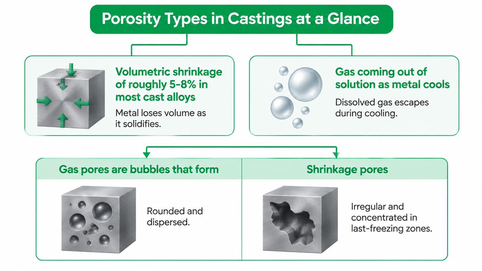
Recognize the pattern before naming the cause
Foundry terminology mixes mechanisms, sizes, and appearances. Microporosity, for example, describes fine-scale voids rather than a completely separate physical cause. Blowholes and pinholes describe recognizable gas-defect forms.
Porosity types, where they form and what drives them
| Type | Appearance | Where It Forms | Main Driver |
|---|---|---|---|
| Gas porosity | Smooth, rounded pores spread through the section | Throughout the section, often evenly | Dissolved gas, especially hydrogen in aluminum |
| Shrinkage cavity | Irregular, rough-walled voids | Last-to-freeze hot spots and heavy sections | Liquid unable to feed contraction |
| Microporosity | Very fine network between dendrites | Interdendritic zones in the mushy region | Incomplete feeding during solidification |
| Blowhole | Large, rounded pores | Near the surface, close to gates or vents | Air entrapment and turbulent filling |
| Pinhole | Tiny surface pores in clusters | At or just below the casting surface | Gas and mold or core moisture |
Use these descriptions as diagnostic clues, not verdicts. A rounded pore doesn't prove that hydrogen caused it, and an irregular pore doesn't exclude a gas contribution.
Dendrites are branching crystals that grow as metal freezes. The spaces between them become narrow feeding passages, which explains why fine porosity can form even without a conspicuous central cavity. These voids may require magnification or suitable internal imaging to resolve.
Connectivity adds another distinction. An isolated pore is an enclosed pocket; connected pores can create a passage for fluid or gas. That passage can matter more to pressure tightness than its contribution to total empty volume.
The hydrogen explanation and aluminum modeling discussed here are aluminum-specific. Don't transfer their operating implications directly to steel, cast iron, or another alloy without checking that material's solidification behavior and casting process.
Gas and Shrinkage Causes Behind Each Pore
In molten aluminum, hydrogen can remain dissolved until cooling reduces the metal's ability to retain it. Once the local concentration becomes high enough, gas pores can nucleate during solidification. Moist charge material, wet handling equipment, and inadequate degassing are practical items to investigate when this pattern appears.
Shrinkage begins with a feeding problem. A heavy boss may remain liquid after the surrounding wall has frozen. If that wall disconnects the boss from its liquid supply, contraction leaves a cavity or fine interdendritic voids.
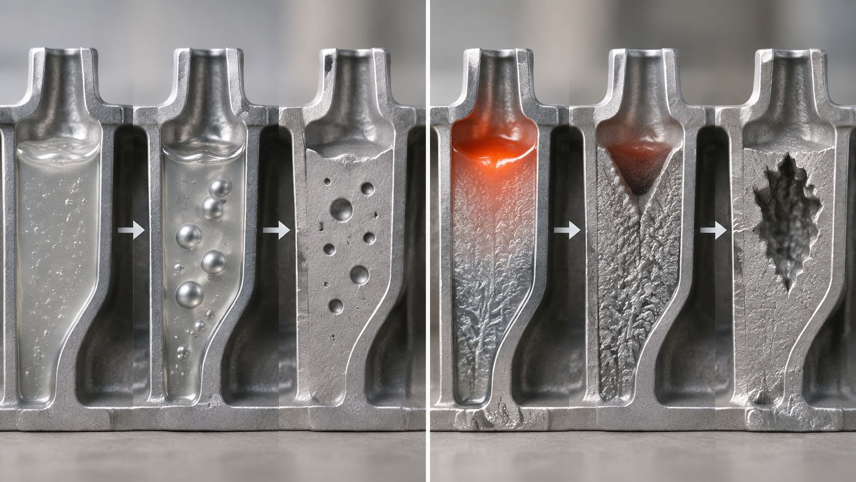
Separate dissolved gas from trapped air
Gas doesn't have to emerge from solution to create a defect. A turbulent flow front can fold air into the melt, while an obstructed vent path can leave cavity air with nowhere to escape. In sand molds and cores, moisture and binder decomposition can supply additional gas.
These distinctions change the investigation:
- Dissolved hydrogen: Examine charge handling, melt treatment, and degassing effectiveness.
- Entrapped air: Examine flow-front behavior, gate entry, shot settings, and vent paths.
- Mold or core gas: Examine drying, binder condition, permeability, and gas escape routes.
- Feeding failure: Examine hot spots, riser connections, and the order in which sections freeze.
Understand why mechanisms overlap
A gas pore can start while liquid still surrounds it, then grow as shrinkage reduces the available feed metal. The finished void may therefore carry evidence of both mechanisms.
Modeling summarized in a review of porosity formation in aluminum castings found pore number inversely proportional to cooling rate and directly proportional to initial hydrogen content; the review also reports that thermal-gradient behavior, solidification rate, and hydrogen content explained about 75% of observed porosity variation in the work discussed.
That finding supports coordinated control, not a universal cooling prescription. Faster cooling can refine the structure, but poorly placed chilling can also close a feeding route before an adjacent region freezes.
Say a thick mounting boss contains mixed pores. Better degassing might reduce gas nucleation without eliminating the boss's feeding deficit. Conversely, improving the feeder won't prevent the melt from picking up hydrogen.
A successful correction must address the conditions that started the pore and those that allowed it to grow. Treat a single-cause explanation cautiously until inspection and process records support it.
Detection Methods and How to Choose One
A clean exterior can conceal internal discontinuities. Choose the inspection method according to the question you need answered: Is there an open surface pore, an internal cavity, a connected leak path, or a potentially dangerous defect beside a loaded feature?
No method answers all those questions equally well. A leak test measures containment performance, while a CT scan maps internal geometry. Passing either test doesn't automatically establish the result of the other.
Match the method to the failure mode
Porosity inspection methods compared
| Method | What It Finds | Main Limit | Best Use |
|---|---|---|---|
| Visual inspection | Open surface pores and blowholes | Blind to internal pores | Every part, first check |
| Dye penetrant | Surface-connected pores | Cannot see subsurface voids | Sealing and machined surfaces |
| Pressure or leak test | Connected porosity that affects tightness | Does not normally map internal pore location or size | Pressure boundaries and fluid housings |
| Radiography (X-ray) | Internal pores on a 2D image | Flat defects may be missed depending on orientation | Screening production lots |
| Industrial CT | 3D pore size, shape and connectivity | Cost and voxel-size uncertainty for small pores | Qualification of critical parts and first articles |
| Ultrasonic testing | Larger internal defects | Affected by coarse grain and surface geometry | Thick sections with simple geometry |
| Metallography | Pore morphology on a cut section | Destructive, samples one plane | Root-cause investigation |
Radiography is useful for finding internal pore fields, but overlapping features can complicate interpretation. CT separates those features spatially, allowing the engineer to examine a pore's distance from a bore, sealing land, or finished wall.
Metallography provides direct evidence of local morphology and microstructure. Its limitation is sampling: a polished section can pass beside a larger pore or cut through only part of a connected network.
Specify what the instrument must resolve
Micro-CT work in the University of Iowa porosity assessment paper identifies volume-weighted pore-size measures correlated with the largest pore, supporting attention to consequential large voids rather than total void fraction alone.
CT still has a resolution limit. A voxel is a volume element in the reconstructed image, and pores smaller than that element carry meaningful measurement uncertainty. A report of no detected pores isn't a promise that no smaller pores exist.
Ask the inspection team to state the region examined, scan resolution, segmentation method, and practical detection limit. Otherwise, comparisons between reports can reflect different measurement settings rather than different casting quality.
A pore percentage without a defined inspection volume, detection capability, and critical location is an incomplete acceptance requirement.
Separate screening from qualification
Qualification establishes whether the proposed process can produce an acceptable part, usually through detailed first-article examination. Screening checks production parts for the defects the control plan requires operators to catch.
Build both into the manufacturing quality-control plan, along with the inspection stage. For a machined fluid housing, final-condition leak testing may be necessary even when the rough casting passed internal inspection.
Consider a housing with dispersed pores in a lightly loaded external rib and a smaller connected cluster beside a bolt hole. The rib could be acceptable under the drawing while the cluster requires rejection. Pore size, location, connectivity, and service conditions determine the decision together.
Tracing a Pore Back to Its Root Cause
Don't begin by changing pressure or adding degassing time. Begin by locating the defect relative to the casting geometry and the manufacturing sequence. Otherwise, you can improve an unrelated variable while the actual defect mechanism continues.
Use a consistent coordinate system so the foundry, inspection team, and design engineer are discussing the same region.
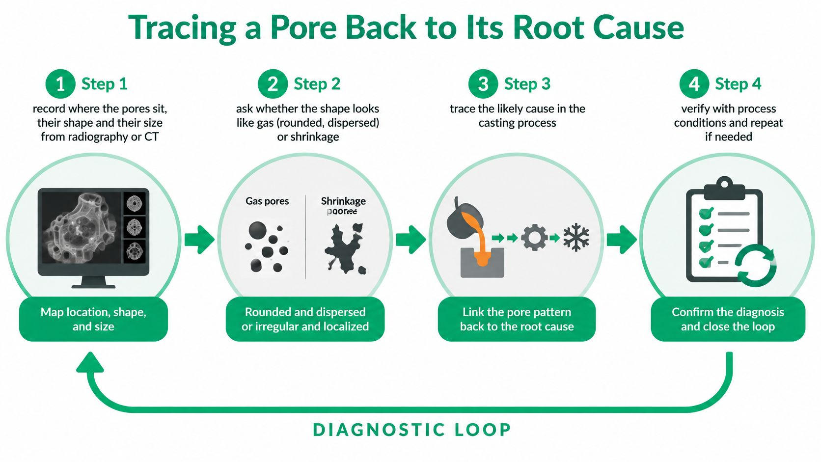
Follow a repeatable diagnostic loop
- Map the evidence. Record pore location, shape, size, and clustering from radiography or CT. Overlay the indication on the finished-part geometry, not only the rough casting.
- Form a provisional diagnosis. Rounded, dispersed pores suggest a gas contribution. Irregular voids concentrated in a thermal hot spot suggest feeding failure, but neither pattern rules out a mixed mechanism.
- Check the process independently. Review melt records, filling and venting conditions, and the solidification sequence separately. Look for evidence that supports or contradicts the initial diagnosis.
- Test a controlled change. Change a targeted variable, keep the remaining conditions stable, and re-inspect the same region using comparable settings.
A high-resolution tomography study of die-casting defects classified air holes, air-shrinkage holes, and shrinkage holes, and found that changing the high-speed ram transition position reduced porous defects in the tested specimens. That's a specific correction tied to filling dynamics, not evidence that every porous casting needs the same shot-profile adjustment.
Choose the next experiment from the evidence
Porosity symptoms, likely causes and corrective actions
| Observed Pattern | Likely Cause | Check to Confirm | Corrective Action |
|---|---|---|---|
| Rounded pores spread through the section | Dissolved gas, usually hydrogen in aluminum | Melt degassing records and reduced-pressure test | Dry the charge, improve degassing, shorten holding time |
| Irregular cavity at a heavy section | Shrinkage at a hot spot | Thermal analysis of last-to-freeze zones | Relocate or enlarge risers, add chills, adjust section thickness |
| Blowholes near gates or vents | Air entrapment | Fill sequence and vent path review | Adjust gate position, enlarge vents, tune filling speed |
| Cluster of pores in a thin, fast-filled area | Turbulent filling | Filling simulation or flow observation | Test a slower local fill and redesigned gating |
| Pores grouped near the ram stop | Ram transition timing | Position of transition versus defect location | Change the high-speed ram transition position and re-inspect |
| Pinholes at the surface | Mold or core moisture | Mold and core drying records | Dry molds and cores, check binder and venting |
Each row describes a working hypothesis, not an automatic machine setting. A reduced-pressure test, for example, helps assess melt condition but doesn't establish the cause of every pore in the finished part.
Keep simulation in that same role. A predicted hot spot tells you where to investigate; it doesn't prove that every observed pore came from shrinkage. Actual melt condition, vent behavior, and local process variation may not be represented adequately in the model.
Close the investigation with physical evidence: the targeted indication changes as predicted, the functional test passes, and repeat pours remain acceptable. A better simulation image alone isn't enough to release the process.
Process and Material Controls That Prevent Porosity
Prevention works best when each manufacturing stage has a defined operating window and an owner. The melt operator controls gas pickup and treatment, the tooling team controls feeding and escape paths, and the process engineer coordinates filling and cooling.
Don't optimize pouring temperature, velocity, and filling time independently. A setting that helps one region can create an unacceptable flow front or feeding condition elsewhere.
Control the melt and the fill together
Keep the charge dry, use dry handling equipment, and verify degassing before pouring. Avoid unnecessary holding and excessive superheat, rather than relying on downstream inspection to catch the consequences.
A numerical casting study predicted increasing porosity as pouring temperature rose from 970 K to 1075 K, and an optimum pouring velocity near 500 mm/s for its modeled system. Those are results for that alloy, mold, and geometry, not transferable production settings.
The practical lesson is to establish a coordinated window. Filling too slowly can disrupt the intended flow and solidification sequence; filling too aggressively can entrain air. Review the gate entry, flow direction, and vent exit together before changing speed.
Preserve a feeding path during freezing
Place feeders so liquid remains available to the regions that solidify last. Use chills to guide the freezing sequence toward that supply, rather than making every region cool faster.
Section transitions deserve particular attention. A heavy pad joined to a thin wall may need geometry changes, local thermal control, or a different feeder connection. Where tooling changes are being considered, 3D-printed molds for casting can support geometry iteration, but they don't remove the need to validate filling and feeding.
Controls that prevent each porosity type
| Stage | Control | Pore It Prevents |
|---|---|---|
| Melt | Dry the charge, degas before pouring, limit holding time and superheat | Gas porosity and pinholes |
| Filling | Set pouring temperature, velocity and fill time together; redesign gating and vents | Blowholes and turbulence clusters |
| Solidification | Place risers for last-to-freeze areas; use chills and section-thickness control | Shrinkage cavities and microporosity |
| Mold and core | Dry sand and cores fully; control binder gas | Surface pinholes |
Use this table as a pre-pour checklist, confirming every row before each pilot pour. Record actual conditions, including departures from the planned settings, so the inspection results can be traced to what operators really ran.
For sand molds and cores, verify drying and gas escape rather than assuming a dry-looking surface proves readiness. After the pilot pour, inspect the predicted critical zones with an appropriate internal method and confirm the functional requirement before locking the window.
Remediation Options for Prototypes and Low-Volume Runs
Say a prototype housing has pores in an external rib but passes its required functional checks. Compare that with a similar housing that leaks through a machined sealing land. Calling both parts porous doesn't justify giving them the same disposition.
Begin with the scenario, drawing requirements, and final condition, then select acceptance, approved repair, process correction, or replacement.
Match the response to the defect
| Scenario | Approach | Trade-off |
|---|---|---|
| Isolated pores in a noncritical region | Document location and size; accept only within drawing requirements | Requires an explicit engineering disposition |
| Connected micropores affecting a sealing region | Consider approved vacuum or pressure impregnation | Adds processing and requires a fresh leak test |
| Near-surface pores beside a machined feature | Review the removal envelope before rework | Machining may expose additional voids or consume the allowance |
| Recurring pores across a batch | Correct gating, venting, degassing, or pour sequence; validate a pilot batch | Delays release while the process is requalified |
| Persistent shrinkage in a heavy section | Change local geometry, feeding, or thermal control | Can require design and tooling expenditure |
| Large void in a structurally critical region | Reject or pursue a formally approved repair route | Replacement may be preferable to uncertain rework |
Impregnation is a sealing treatment, not a general structural repair. It can address suitable connected micro-leak paths when the application permits it, but it doesn't replace missing load-bearing metal.
Agree on the treatment stage before work begins. Impregnation before machining may leave newly exposed paths afterward, so the finished condition still needs verification. A cosmetic improvement isn't evidence of restored containment.
Protect the prototype's validation purpose
For recurring defects, segregate the affected lot and establish a corrected pilot process before releasing more parts. Use CT or radiography where necessary to confirm that the change improved the intended region rather than shifting the defect elsewhere.
Rework check: Overlay the pore map with the finished machining envelope before approving another cut. Removing a visible pore may expose a larger connected region beneath it.
Also distinguish metal-casting validation from replica evaluation. A polyurethane part or printed model can support geometry, assembly, and handling checks, but it doesn't reproduce metal solidification shrinkage or dissolved-hydrogen behavior.
The vacuum-casting process for polyurethane replicas is useful for a different development question. Don't use a successful resin replica as proof that the corresponding metal casting will be internally sound.
Confirm Your Inspection and Fix Path Before the Next Run
Release the next run against a documented decision, not a general instruction to reduce porosity. The drawing, inspection plan, and process record should describe the same critical regions.
Use this sequence to close the decision:
- Set acceptance by function. Define permitted pore size and location for pressure boundaries, fatigue-sensitive features, sealing faces, and finished walls. Identify less critical regions separately.
- Select the inspection level. Assign production screening and first-article qualification methods, including their detection capability and inspection stage.
- Approve the disposition. Document acceptable isolated indications, authorize any suitable impregnation and retesting, or require a corrected pilot batch.
- Confirm the operating window. Compare simulation with physical inspection and functional tests before releasing the lot.
For separate replica-development needs, our polyurethane vacuum casting at FIRMFG uses silicone molds for small-batch parts. Our standard lead time is 5–7 days, and our ISO 9001:2015-certified service includes dimensional inspection reports and First Article Inspection as standard.
That route supports appropriate form, fit, and function evaluations. It doesn't qualify a metal foundry's internal soundness, so keep replica acceptance and metal-casting acceptance as separate engineering decisions.
For low-volume polyurethane replicas, we can help select the resin grade, mold strategy, and inspection documentation around your development requirements. Visit FIRMFG with your CAD model, intended use, and critical features to discuss a prototype route without confusing replica validation with proof of metal-casting soundness.