Precision Metal Machining: A 2026 Guide
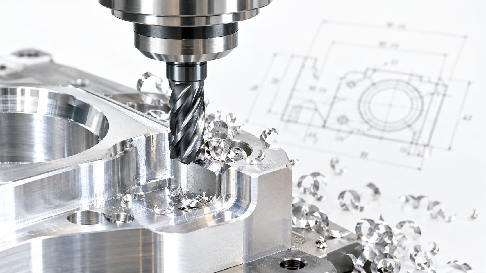
A prototype is due on the test bench Friday. The drawing calls for hard datums, a deep pocket, a few small holes, a cosmetic outside face, and a tolerance that looks harmless until someone asks how it will be measured. The CNC machine may be available, but that doesn't mean the part is ready to make.
Precision metal machining is a decision chain. Material behavior affects tool choice, tool choice affects surface integrity, workholding affects geometry, and inspection determines whether the finished part can be accepted with confidence. A drawing tolerance without a measurement plan is only a target on paper.
This guide is for design engineers, NPI teams, procurement specialists, and R&D groups building automotive, medical, robotics, and industrial hardware. It focuses on the choices that decide whether a part is repeatable and economical, from process selection and DFM feedback to datums, inspection uncertainty, and supplier quality systems.
Table of Contents
Core Methods That Define Precision Metal Machining- Match the method to the geometry
Material Behavior and Machinability in Precision Work- Don't copy cutting data between alloys
Tolerances, Surface Finish, and the Standards Behind Them- Build the callout around the function
Inspection Reality and Why Stated Tolerances Can Lie- Choose the instrument by feature risk
Design for Manufacturability Tips That Save Cost and Lead Time- Change the drawing before changing the machine
Applications Across Automotive, Medical, and Robotics
Quality Systems, Lead Times, and Choosing a Machining Partner
Why Precision Metal Machining Matters for Modern Engineers
The difficult prototype isn't always the part with the most complicated CAD model. Often, it's the part that combines ordinary features under conflicting requirements. A machined housing may need flat mounting surfaces, concentric bores, thin walls, a tight positional relationship between holes, and a clean cosmetic finish. Each requirement can be achievable alone. Together, they create a process and inspection problem.
A capable machine is only one part of the answer. The programmer must choose a setup that protects the functional datums. The machinist must account for cutting forces, tool deflection, heat, burr formation, and material movement. The inspector must then reproduce the intended datum scheme and use equipment capable of distinguishing a real deviation from measurement noise.
Practical rule: If the supplier can't explain how a critical feature will be made and measured, the tolerance hasn't been engineered yet.
The scale of the machining workforce reinforces the human side of the process. The U.S. Bureau of Labor Statistics machinist profile estimated 290,720 machinists employed in May 2023, with a mean annual wage of $54,600. Machine shops, turned-product manufacturers, and screw, nut, and bolt producers represented 21.9% of that occupation, which is a useful reminder that precision parts still depend on drawing interpretation, tooling decisions, workholding, and verification.
What this decision chain must answer
Before releasing a drawing, ask practical questions rather than starting with a machine brand:
- Process: Does the geometry suit 3-axis milling, turning, 5-axis machining, grinding, or EDM?
- Material: Will the alloy generate stable chips, hold a sharp edge, or work-harden under repeated passes?
- Tolerance: Does every tight callout support a functional requirement, or is it inherited from an old drawing?
- Inspection: Which features require a CMM, and which can be verified with calibrated gauges?
- Documentation: Will the supplier provide first-article results, material traceability, and a clear record of deviations?
A prototype that arrives on time but fails assembly has not shortened the development cycle. The useful supplier is the one that identifies an impossible setup, an over-specified surface finish, or an inspection gap before metal is cut.
Core Methods That Define Precision Metal Machining
Precision metal machining removes material under controlled motion so a digital design becomes a physical part with defined geometry. The correct process depends less on the machine's headline specification than on feature access, setup count, material response, and the way the part will be inspected.
A practical overview of CNC machining processes helps establish the broad process families, but selection should start with the part's dominant features.
Match the method to the geometry
3-axis milling is effective for prismatic parts with features accessible from the top or from a small number of planned setups. It offers a straightforward programming and inspection path, but each additional setup introduces another opportunity for datum transfer error, workholding variation, and accumulated positional deviation.
4-axis machining adds rotary positioning around one axis. It can expose multiple sides of a part without manually reclamping it, making it useful for indexed holes, radial features, and parts that need more access than a fixed three-axis arrangement provides.
5-axis machining earns its cost when tool access and setup reduction matter. Simultaneous motion lets the cutter approach sloped surfaces, compound contours, and multiple faces while maintaining a controlled tool orientation. It can reduce re-fixturing, but it doesn't automatically make every dimension more accurate. A poorly supported part, unstable cutting condition, or weak datum strategy remains a problem on a 5-axis machine.
CNC turning suits rotational parts such as shafts, pins, bushings, and threaded bodies. Live tooling adds milling, drilling, and cross-hole capability in the same turning setup, which can preserve concentricity between turned and milled features.
Micro machining requires more than a small cutter. Tool runout, spindle behavior, chip evacuation, burr control, and inspection resolution become central concerns. A tiny feature can be easy to cut but difficult to verify consistently.
Wire EDM is valuable for profiles in hardened tool steel and other electrically conductive materials where conventional cutting tools would struggle with hardness, slender geometry, or narrow internal features. It doesn't replace milling. It adds a non-contact option when the geometry or material makes cutting forces unacceptable.
Grinding and honing remain finishing processes when a drawing demands highly controlled size, form, or surface texture. They remove less material than milling or turning, so the design and process plan must leave appropriate stock.
| Process | Typical tolerance band | Best-fit geometry | Notable trade-off |
|---|---|---|---|
| 3-axis milling | Drawing-dependent | Prismatic pockets, faces, holes | More setups can increase datum-transfer risk |
| 4-axis milling | Drawing-dependent | Indexed radial and multi-side features | Limited compared with full simultaneous access |
| 5-axis milling | Drawing-dependent | Compound surfaces and multi-face parts | Higher programming and fixturing complexity |
| CNC turning | Drawing-dependent | Shafts, bores, threads, rotational forms | Less suitable for non-rotational geometry |
| Wire EDM | Drawing-dependent | Hardened profiles and narrow slots | Requires conductive material and post-process planning |
| Grinding or honing | Drawing-dependent | Finishing size, form, and surface texture | Usually needs prepared stock and additional handling |
The phrase “tight tolerance” isn't a process choice. It describes a requirement that must be connected to geometry, material, tooling, and inspection.
Material Behavior and Machinability in Precision Work
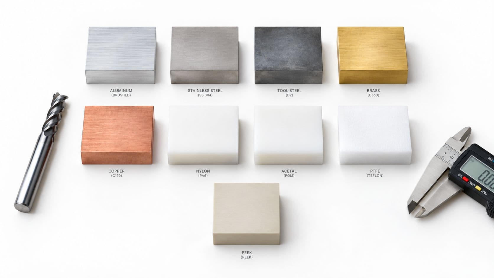
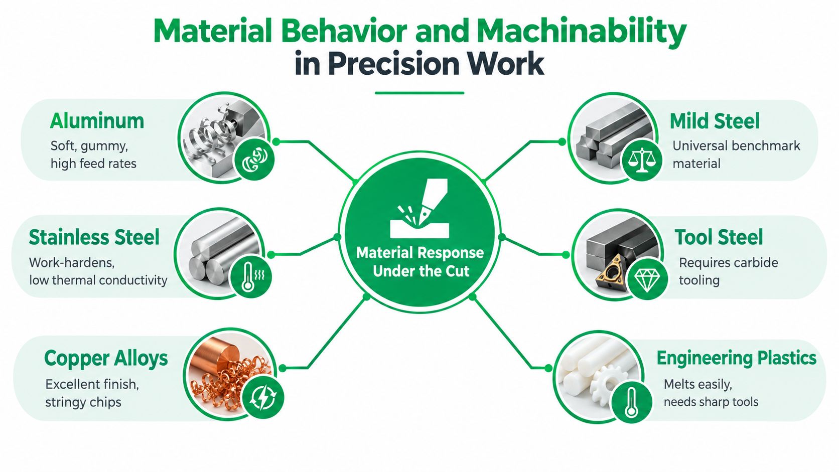
A toolpath that works cleanly in aluminum can fail in stainless steel, and a feed that produces a good finish in mild steel may create burrs or heat damage in copper alloy. Material selection changes the cutting problem before the programmer opens the CAM file.
Aluminum usually cuts easily, but soft grades can become gummy and encourage built-up material on the tool. Sharp tooling, effective chip evacuation, and controlled workholding help prevent burrs and surface smearing. Stainless steel brings the opposite concern. It can work-harden, conduct heat poorly, and punish rubbing, so the tool must cut decisively rather than dwell against the surface.
Mild steel is often a useful baseline because it offers a relatively balanced combination of strength, chip formation, and tool response. Tool steel demands more attention to hardness, rigidity, tool grade, and heat. Copper alloys conduct heat well and may produce stringy chips, while engineering plastics can deform or melt when cutting energy and heat aren't controlled.
Don't copy cutting data between alloys
The machining-material guidance for CNC work is useful as a starting point, not as permission to transfer parameters unchanged between materials. The actual response depends on alloy condition, heat treatment, cutter geometry, tool coating, coolant, engagement, and how well the part is supported.
A study of ductile cast iron illustrates the conflict between objectives. Its longest measured tool life was 41.34 minutes at 180 m/min cutting speed, 0.10 mm per tooth feed, and 0.30 mm depth of cut, while its best surface finish occurred at a different condition, 260 m/min, 0.10 mm per tooth, and 0.90 mm depth of cut. Those values come from the study of milling ductile cast iron, and they show why “optimal” has to be tied to an objective.
For a prototype, I would rather see a stable roughing pass followed by a measured finishing adjustment than a nominal speed copied from a material chart. Confirm rigidity, workholding, coolant delivery, and chip evacuation first. Then monitor tool wear through part count or cutting time, not only through final inspection. As flank wear grows, roughness can deteriorate and dimensions can drift together.
Tolerances, Surface Finish, and the Standards Behind Them
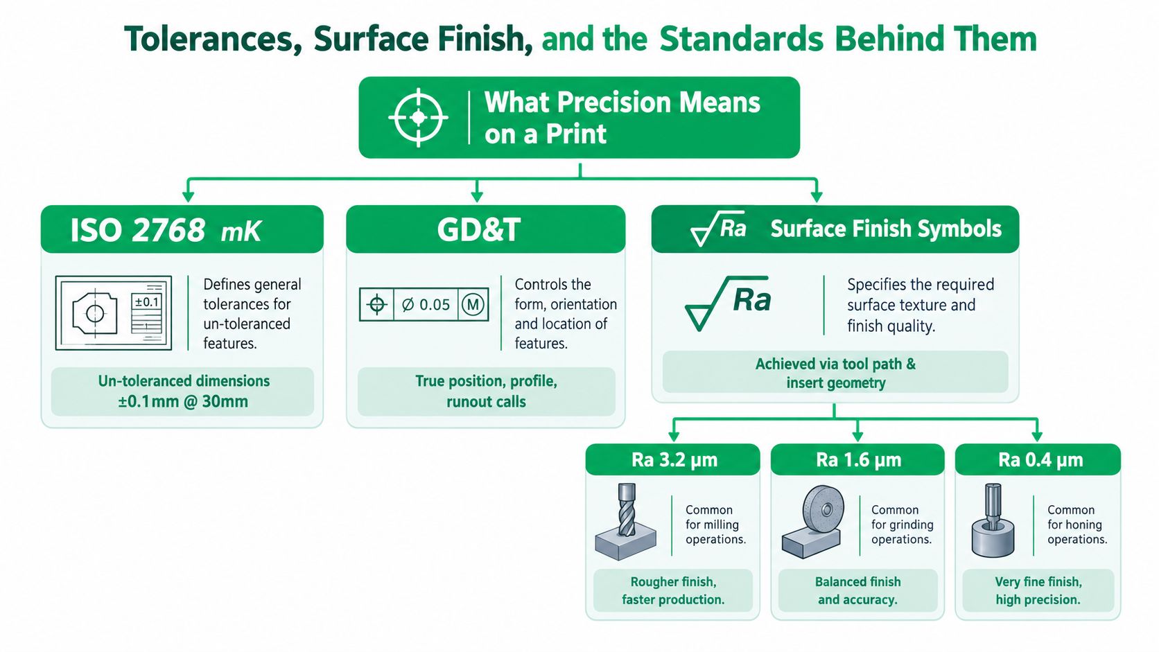
Precision starts with a drawing that distinguishes functional requirements from manufacturing preferences. A size tolerance controls how large or small a feature may be. GD&T controls relationships such as position, profile, orientation, and runout. A surface-finish symbol describes texture, but it doesn't explain by itself how the shop should achieve it.
ISO 2768 can provide general tolerances for dimensions that lack individual callouts, but a general tolerance isn't a substitute for functional GD&T. The applicable class, material, feature size, and drawing standard must be confirmed before anyone treats a general table as an acceptance rule.
Build the callout around the function
Start with the assembly or performance requirement. If a shaft must rotate in a bearing, concentricity, diameter, surface texture, and material condition may matter together. If a plate only needs to provide a mounting surface, a broad profile or flatness requirement may be more appropriate than a narrow size tolerance on every edge.
Milling, turning, grinding, and honing leave different surface signatures. Cutter diameter, insert nose radius, feed, toolpath direction, vibration, and tool wear influence the resulting texture. Grinding can improve size and surface control after rough machining, while honing is typically reserved for a controlled bore or mating surface where the final texture supports the function.
Use standards to start a DFM conversation
A good drawing tells the supplier which features deserve attention. It doesn't force every surface into the same manufacturing burden. Review these points before release:
- Identify functional datums. Choose surfaces that locate the part in the actual assembly, not merely surfaces that are convenient in CAD.
- Separate size from geometry. A hole diameter tolerance won't control the hole's relationship to another feature. Use position or profile when the relationship is what matters.
- Specify finish by function. Sealing, sliding, optical appearance, and adhesive bonding can require different surface strategies.
- Remove inherited precision. A tight callout copied from a previous component can create unnecessary inspection and finishing work.
- Define the inspection method. State which features need CMM, height-gauge, bore-gauge, or functional-gauge verification.
The historical progression of machining shows why inspection belongs in the same conversation as production. A NIST review of machining capability and metrology reports that a common machining tolerance around 1918 was approximately ±50 micrometres, while high-accuracy parts by 1917 were made to about ±6.25 micrometres, with ±2.5 micrometre tolerances already being pursued. The review estimates that ordinary precision machining improved by roughly an order of magnitude every 20 years, reaching below 1 micrometre in achievable tolerances from about 1980 onward, while modern ultra-precision work can reach approximately 1 to 10 nanometres. The lesson isn't to chase the smallest number. It's to make the production and measurement chain credible at the number you need.
Inspection Reality and Why Stated Tolerances Can Lie
A supplier says a feature holds ±0.01 mm. The part still fails at assembly because the result depended on how it was measured, how it was fixtured, and which surfaces were treated as datums. That is the inspection problem in precision machining. A tolerance on the drawing is only credible if the measurement method can support it.
A CMM and a digital caliper do not give the same level of evidence. A 2025 comparison across five engineering materials found CMM expanded uncertainty as low as 0.00166 mm, while digital calipers reached up to 0.03333 mm. In areas affected by surface degradation and fixture variation, propagated caliper errors exceeded 0.035 mm, according to the study comparing calipers and CMMs.
Choose the instrument by feature risk
Calipers, micrometers, bore gauges, and height gauges are useful when the feature is accessible, the contact points are obvious, and the tolerance leaves enough room for gauge uncertainty. They are weak tools for freeform surfaces, true position, profile, thin unsupported sections, and any requirement that depends on a datum reference frame rather than a single size check.
That is why process choice and inspection choice have to stay connected. If a drawing calls for positional control across multiple faces, a shop cannot judge capability from spindle specs alone. It needs a measurement setup that matches the way the part functions.
Use a CMM when feature relationships matter, when datums must be established in sequence, or when the result may need to stand up in a customer review or corrective action. Probe behavior also changes the answer. Touch-trigger and scanning probes do not respond the same way, and scanning generally produces lower uncertainty on contoured surfaces. The practical point is straightforward. Probe type, stylus setup, fixture stiffness, temperature, and point strategy all influence whether a reported pass result means anything.
Ask this before approving a report: What is the instrument uncertainty relative to the tolerance, and how were temperature, datums, probe direction, and fixture repeatability controlled?
A sound inspection record captures part condition, measurement temperature, calibration status, datum setup, probing plan, and the acceptance rule. Review the supplier's CMM inspection service workflow at that level, not just whether a CMM is listed on the equipment sheet.
Design for Manufacturability Tips That Save Cost and Lead Time
DFM is where a drawing becomes easier to make without weakening the product. The best changes often look unremarkable in CAD: a standard internal radius, a reachable wall, a datum that matches the assembly, or a tolerance removed from a non-functional edge.
Change the drawing before changing the machine
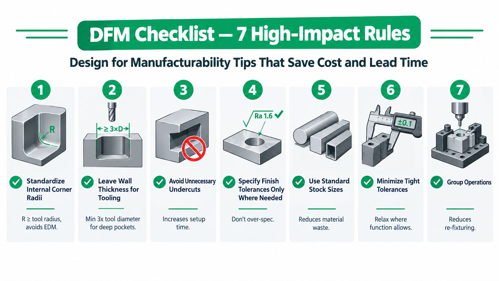
Use standard internal corner radii. A square internal corner usually requires a smaller cutter, multiple passes, or a secondary process. Add a radius that matches available tooling unless the assembly needs a sharp corner.
Protect wall stability. Deep, thin walls deflect under cutting force and may spring back after the tool leaves. Increase wall support, shorten tool reach, or redesign the pocket so the supplier can hold the feature without treating the part as a flexible membrane.
Avoid decorative undercuts. An undercut can require special tooling, a different setup, or wire EDM. Keep it when it performs a real mechanical function, not because the CAD model makes it convenient.
Design threads for available tools. Standard thread forms and accessible starts are easier to make and inspect. If a thread sits at the bottom of a blind hole, provide clearance for the tap or thread mill and specify the required full-thread length.
Let function decide the tolerance
Use a tight tolerance on a bearing seat, locating feature, sealing surface, or controlled interface when the function requires it. Don't apply the same restriction to every outside face. A broad non-functional surface can often be machined in the same operation with less inspection burden.
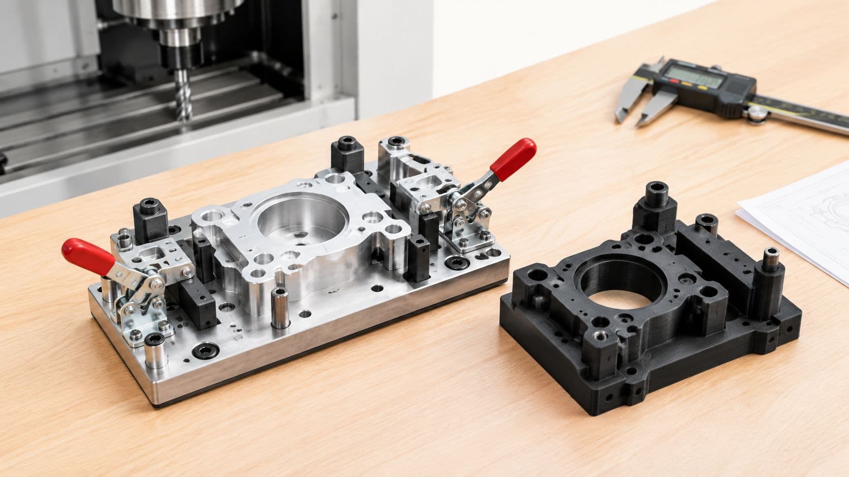
Choose datums that match assembly behavior. If the part locates against a machined shoulder, that shoulder should usually influence the datum strategy. A datum that exists only because it was easy to select in CAD can force unnecessary setup transfers and confuse inspection.
Design review test: Remove one tight tolerance at a time and ask what failure it prevents. If the team can't name the failure, the callout deserves another review.
Use standard stock where possible, group operations that share a setup, and leave access for tools and probes. These decisions reduce re-fixturing and make the inspection plan clearer. They also respect the people operating the process. The BLS profile cited earlier shows that machinists remain central to converting drawings into repeatable parts, and their judgment covers tool selection, offsets, workholding, and verification rather than button-pushing alone.
Applications Across Automotive, Medical, and Robotics
Automotive parts often combine structural loads, repeatable interfaces, and production-oriented inspection. Sensor housings, transmission components, battery enclosures, and powertrain brackets may need accurate bores, flat mounting faces, controlled threads, and reliable sealing surfaces. Turning handles rotational shafts and bushings, while 3-axis or 5-axis milling suits housings and multi-face components.
Medical components add material and documentation constraints. Surgical instruments may require controlled edges, clean surfaces, corrosion-resistant alloys, and consistent mating features. A machined implant or device component needs a process route that respects the specified material condition, finishing requirements, and inspection records. The question is not merely whether a machine can cut the shape. It is whether the supplier can preserve traceability through machining, finishing, cleaning, and release.
Robotics depends heavily on interfaces that repeat under motion. Gear-reducer housings, joint plates, bearing seats, motor mounts, and end-effector components can be sensitive to concentricity, parallelism, flatness, and surface damage. A 5-axis setup may reduce handling for a complex joint component, while turning with live tooling can preserve relationships between a bore, cross-holes, and milled mounting features.
The process follows the failure mode. If alignment drives performance, prioritize datums and relational inspection. If surface integrity affects sealing or motion, control tooling, wear, and finish together. If a feature is inaccessible with conventional cutting, consider EDM or a redesigned geometry before forcing a tolerance that the chosen process can't verify efficiently.
Quality Systems, Lead Times, and Choosing a Machining Partner
A quality certificate matters when it changes daily behavior. ISO 9001 should translate into controlled processes and corrective action. ISO 13485 matters when medical work requires device-focused traceability and documentation. IATF 16949 capability matters for automotive programs that demand disciplined process control and customer-specific requirements.
Evaluate a supplier by asking for its inspection method, material records, DFM response, deviation process, and communication path. Quote speed, prototype availability, no-MOQ support, finishing coordination, and global logistics also affect actual lead time. A fast machine can't compensate for a slow technical review or an unclear inspection report.
FIRMFG offers CNC milling, turning, simultaneous 5-axis machining, micro machining, wire EDM, finishing, and related prototype and low-volume manufacturing services, with ISO 9001 and ISO 13485 frameworks and IATF 16949 capability for automotive-related work. Its model combines technical DFM feedback, documented inspection, and support from prototype development through pilot production.
Share your drawing, material, functional tolerances, finish requirements, and target quantity with FIRMFG for a process review grounded in manufacturability and inspection capability. Ask the team to identify setup risks, measurement requirements, and opportunities to reduce cost or lead time before production begins.