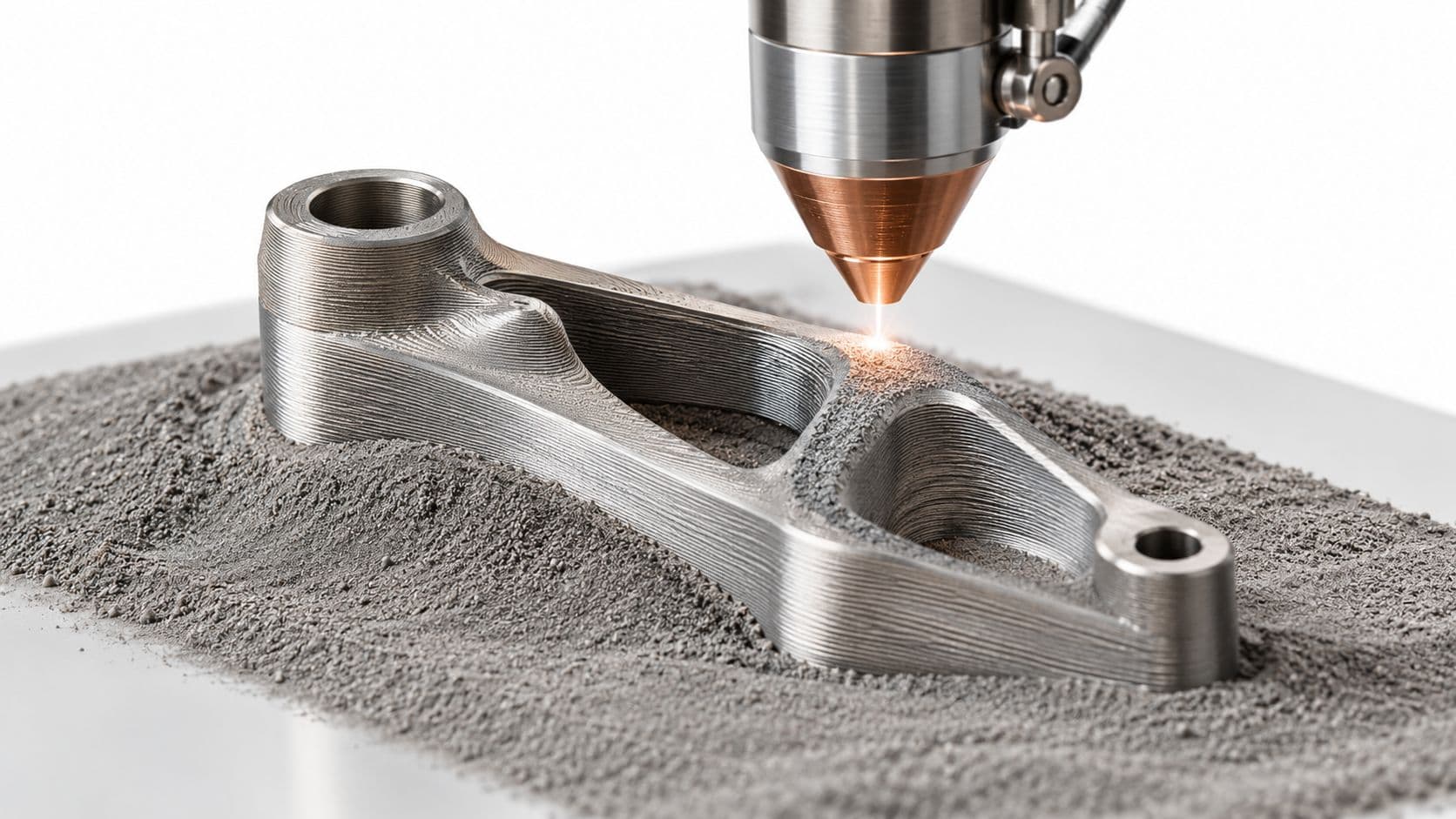
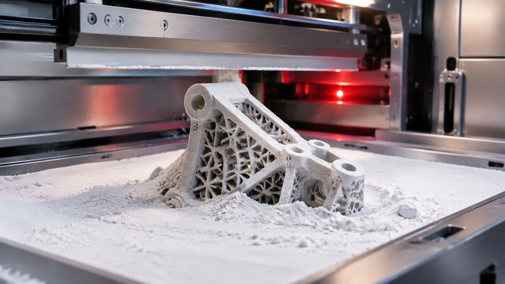
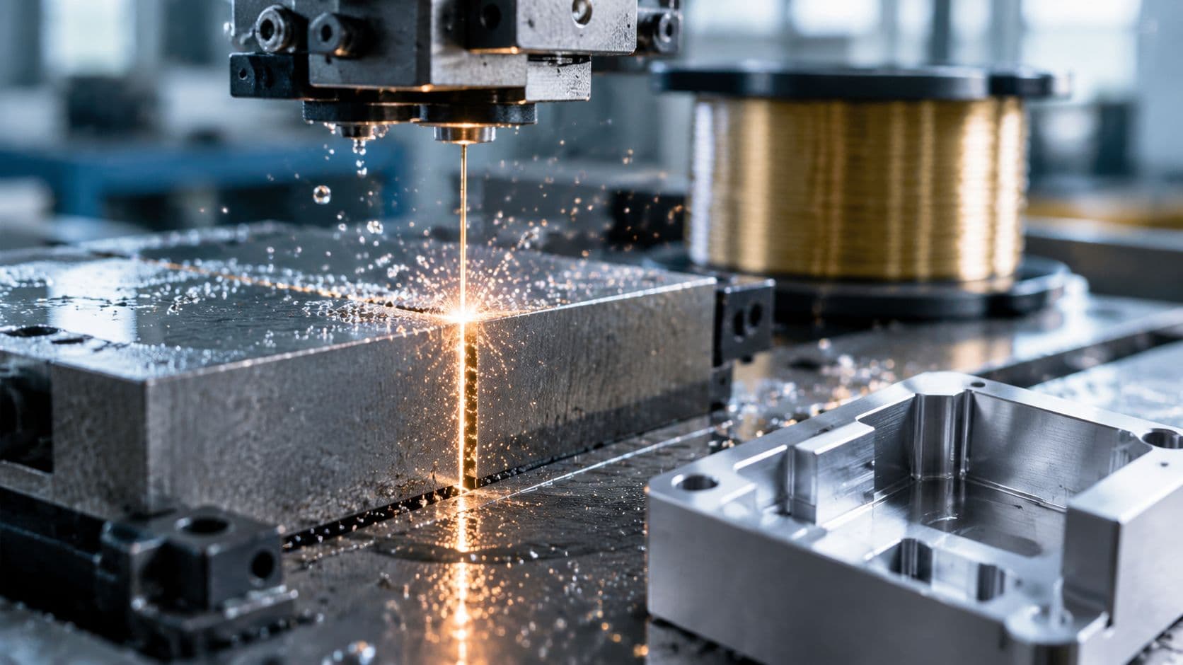
CNC Machining Process: A Complete Engineer's Guide
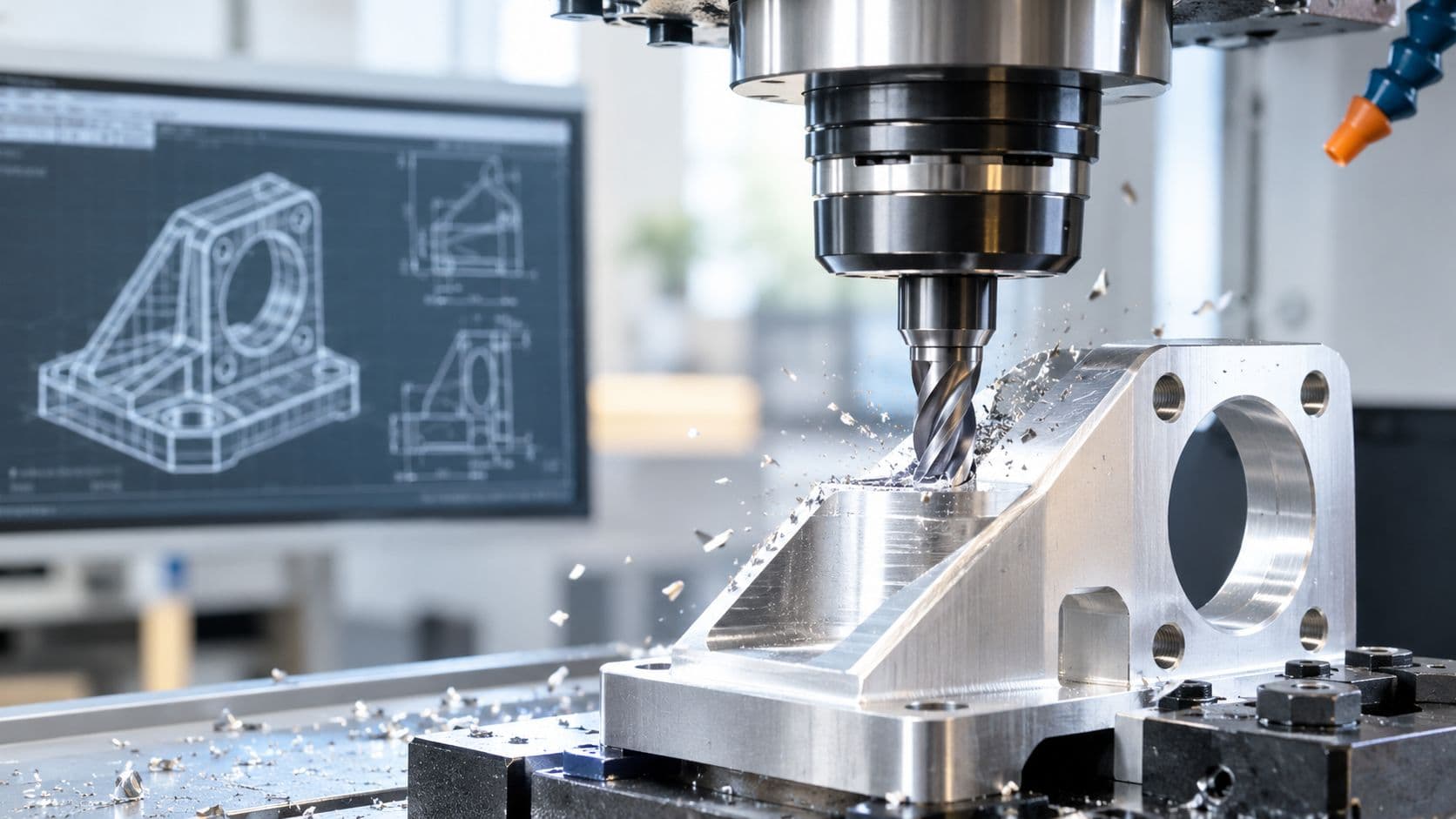
You submit what looks like a simple bracket to three machine shops and receive quotes of $48, $310, and something in between. Lead times range from five to nineteen days. The drawing is identical, so the numbers feel arbitrary.
They aren't. The difference usually sits inside the CNC machining process, in tolerance callouts, feature orientation, material condition, batch size, workholding, tool access, finishing, and inspection. A shop isn't quoting only the minutes when a cutter removes metal. It's quoting the engineering work required to make the part repeatably, verify it, and deliver it without discovering at final inspection that the design was never practical to machine.
Table of Contents
The End-to-End CNC Machining Workflow- Start with complete design data
- Lock the machining strategy in CAM
- Secure the workpiece and establish coordinates
- Cut, control chips, and monitor the process
- Finish and verify
3-Axis, 4-Axis, and 5-Axis Machining Compared- Choose the machine around the part
Machining Parameters That Actually Drive Results- Surface finish follows the chip geometry
Materials, Tolerances, and What They Really Cost- Translate the drawing into process effort
Common Failure Modes and How to Fix Them- Chatter on thin walls
Lead Time, Cost Drivers, and DFM Tips- DFM decisions that move the quote
Bringing It All Together for Better Parts
Why the CNC Machining Process Matters for Engineers
A bracket can be inexpensive when its functional faces are reachable in one setup, its holes use standard tooling, and its tolerances match the way the part carries load. The same bracket becomes expensive when every face needs a separate orientation, a thin wall must remain stable during cutting, cosmetic surfaces need protection, and a general tolerance is applied to dimensions that don't affect assembly.
That distinction matters most during prototyping. A one-off or very small batch absorbs programming, setup, workholding, and inspection effort into a small order. If the drawing also specifies tight tolerances everywhere, the shop may need additional passes, controlled temperature, probing, and more detailed inspection. You may get a technically impressive part, but you'll pay for precision the product doesn't use.
Practical rule: A tolerance is a manufacturing instruction, not a decoration on the drawing.
The first question isn't “How accurate is the machine?” It's “Which dimensions establish function?” Identify the datum surfaces, bearing fits, sealing lands, hole locations, and interfaces that control assembly. Then separate those from reference dimensions and noncritical surfaces. A shop can plan the process around the important requirements instead of treating every dimension as equally urgent.
Why tolerance charts mislead
Public CNC charts often advertise tight capability figures, including ranges such as ±0.005 mm to ±0.025 mm, but those values are generally capability benchmarks rather than default results on every geometry. Tolerance guidance from Survi highlights the gap between machine-level capability and the tolerance a real part can hold after fixturing, material movement, tool wear, and thermal effects.
A long hole, thin wall, deep pocket, or flexible plastic component can behave very differently from a short, accessible feature cut from a stable metal block. The machine may be capable of a tight move, yet the complete process may not hold that result economically.
The historical development of CNC also explains why the workflow depends on common programming conventions. ISO 6983-1 was circulated to member bodies in May 1980 by ISO/TC 97, an important milestone in standardizing computer numerical control programming for tool motion, positioning, and machining instructions. The ISO 6983-1 document captures that transition from specialized numeric control toward broadly deployable computer-driven manufacturing.
Understanding the process lets you influence cost before the quote arrives. You can orient features for access, choose a sensible stock form, relax unused tolerances, and tell the shop what the part must do. That information is more valuable than asking for the lowest unit price.
The End-to-End CNC Machining Workflow
A reliable part moves through a chain of decisions. Each stage creates constraints for the next one, so a clean digital model can't compensate for poor workholding, and a good fixture can't rescue an ambiguous drawing.

Start with complete design data
The CAD model defines solid geometry, but the shop also needs manufacturing intent. Supply a STEP file for 3D machining, a controlled drawing with materials and finishes, and GD&T that identifies functional relationships. Include revision information, units, thread specifications, and any surfaces that must remain cosmetic.
A STEP file prevents the CAM programmer from rebuilding geometry. The drawing tells the programmer which geometry matters.
Lock the machining strategy in CAM
The programmer imports the model, defines stock, selects tools, establishes work coordinate systems, and creates toolpaths. Simulation checks collisions, holder clearance, remaining stock, and the order of operations before the code reaches the machine.
At this point, workholding is already part of the machining strategy. A toolpath that looks efficient in isolation may become unusable if the vise blocks access or a clamp sits inside the cutter's travel.
Secure the workpiece and establish coordinates
A standard vise may be appropriate for a prismatic part. Soft jaws locate a repeat job more consistently, while vacuum tables suit thin sheet-like components. A custom fixture becomes worthwhile when the part has irregular geometry, delicate surfaces, or multiple orientations that must repeat.
The operator then sets work offsets, tool lengths, and probing routines. In-process probing can verify stock position and locate datums before cutting, which is especially useful when the raw material or fixture has limited repeatability.
Cut, control chips, and monitor the process
Milling centers rotate the cutter against a secured workpiece. Turning centers rotate the workpiece against a stationary cutting tool. Coolant carries heat away and helps evacuate chips, but the correct approach depends on material, tool geometry, pocket depth, and machine enclosure.
For a practical overview of the service flow, see FIRMFG's CNC machining service. The important point is that cutting isn't an isolated event. Tool selection, chip evacuation, coolant delivery, and probing all affect whether the inspection stage confirms the intended geometry.
Finish and verify
After machining, operators remove burrs and sharp edges, then inspect the part against the original drawing and GD&T. Calipers, micrometers, gauges, probes, and CMM inspection each suit different requirements. Anodizing, bead blasting, powder coating, polishing, and other finishes may follow, but the drawing should state whether dimensions apply before or after finishing.
Inspection confidence comes from the same datum structure used during machining. If the part was located from one surface but inspected from another without a defined relationship, a disagreement can appear even when both people measured carefully.
3-Axis, 4-Axis, and 5-Axis Machining Compared
Axis count isn't a ranking system. It's a geometry and setup decision.
A 3-axis machine moves the cutter in three primary linear directions. It suits brackets, plates, housings, pockets, slots, and other prismatic parts where the important features can be reached from the top or through a limited number of planned setups. A rectangular enclosure rarely benefits from 5-axis programming because the machine has that capability.
A 4-axis machine adds rotary positioning. That extra movement can expose multiple sides of a part, machine wraparound features, or drill holes on curved faces without removing and manually re-aligning the workpiece. A part with six holes distributed around a curved face may cost less in 4-axis production than in 3-axis production because the rotary setup reduces re-fixturing and coordinate-transfer work.
A 5-axis machine provides access to multiple faces and can support simultaneous multi-side cutting. Impellers, manifolds, sculpted housings, and undercut geometry can justify it, particularly when one setup improves feature relationship and reduces accumulated alignment error. It still isn't automatically faster. Programming, simulation, collision checking, specialized tooling, and fixturing can increase the front-end effort.
Choose the machine around the part
| Axis Configuration | Best-Fit Geometry | Indicative Cost vs 3-Axis | When It Pays Off |
|---|---|---|---|
| 3-axis | Brackets, plates, enclosures, open pockets | Baseline | Most features are accessible with straightforward setups |
| 4-axis | Wraparound faces, radial hole patterns, cylindrical surfaces | Higher when the rotary setup isn't needed | Rotary positioning removes repeated re-fixturing |
| 5-axis | Manifolds, impellers, undercuts, complex multi-sided forms | Higher programming and setup burden | Single-setup access or complex tool orientation protects accuracy and lead time |
Machine-selection test: If the geometry doesn't require additional access, extra axes add capability without adding value.
A 5-axis quote can make sense when the alternative requires several difficult setups, long tools, or manual alignment. It can also be wasteful for a simple housing. This guide to 5-axis CNC milling is useful when evaluating whether simultaneous access solves a real geometry problem or merely raises the machine category.
The best choice balances tool access, datum control, setup count, programming complexity, and inspection strategy. A lower-axis machine with a well-designed fixture may outperform a higher-axis machine on a simple part.
Machining Parameters That Actually Drive Results
Spindle speed, feed rate, depth of cut, and cutter choice work as a coupled system. Changing one without reconsidering the others often creates the exact problem the change was meant to solve.
Spindle speed follows cutting speed and tool diameter. As tool diameter changes, the required RPM changes with it. Feed rate then depends on feed per tooth, tooth count, and spindle speed. If the cutter has more teeth or the spindle turns faster, table feed must be coordinated so the tool still produces an appropriate chip.
Radial engagement often controls chatter more than the headline RPM value. A wide cutter engagement increases cutting force and deflection, while a lighter radial cut can stabilize a thin wall and maintain chip formation. Axial depth of cut also matters, but designers frequently miss the effect of how much of the cutter is engaged laterally.
Surface finish follows the chip geometry
Feed rate has a direct geometric relationship with the marks left by a turning tool. A statistical study found feed rate had the strongest effect on Ra, with F = 25.23 and P = 0.001, while cutting speed showed a much smaller effect, F = 0.08 and P = 0.923. The turning surface-finish study supports a practical priority: reduce feed per revolution for a finish-critical operation before assuming higher spindle speed will fix the surface.
For milling, feed per tooth and stepover shape the scallop pattern and cutting load. A finishing pass with stable engagement can improve the surface more reliably than increasing RPM.
Tool life is a thermal and mechanical balance
Tool wear depends on feed, cutting speed, depth of cut, contact length, coolant, and material. Research on tool wear identifies feed rate as a major influence, followed by depth of cut and cutting speed, while longer engagement can accelerate edge degradation. The tool-wear research reinforces that slowing one parameter alone isn't a complete tool-life strategy.
Aluminum 6061 generally accepts sharper, high-speed tooling and efficient chip evacuation. P20 tool steel needs a more controlled balance of engagement, heat, and tool rigidity. A trochoidal slot in 4140 can use low radial engagement and maintain material removal while reducing heat concentration at the edge. The exact starting values belong in the toolmaker's catalog and the shop's validated process, not in a universal chart.
| Material | SFM (m/min) | Feed/Tooth (mm) | DOC Guidance |
|---|---|---|---|
| Aluminum 6061 | Use toolmaker guidance | Use toolmaker guidance | Favor efficient chip evacuation and stable engagement |
| Tool steel P20 | Use toolmaker guidance | Use toolmaker guidance | Reduce engagement when rigidity or heat is limiting |
| 4140 steel | Use toolmaker guidance | Use toolmaker guidance | Consider adaptive or trochoidal paths for deep material removal |
These qualitative ranges are intentional. Material hardness, cutter coating, diameter, machine rigidity, coolant delivery, and workholding can change a safe starting point substantially.
Materials, Tolerances, and What They Really Cost
Material choice changes both the cutting mechanics and the tolerance risk. Aluminum 6061 is generally straightforward to machine and deburr, while 7075 may be selected when strength matters more than easy cutting. 1018 steel is relatively workable but can leave a different burr profile from 4140, especially as heat treatment and hardness increase.
Delrin machines cleanly when the cutter stays sharp and heat remains controlled. PEEK can demand more careful temperature management and fixturing. ABS is easier to cut than many engineering plastics, but thin sections can still move when residual stress is released.
Deep pockets create chip-evacuation problems in metals and plastics. Long reach tools deflect, trapped chips recut, and a design that looked rigid in CAD can vibrate on the machine. Plastics often need rough machining, a rest period or stress-relief strategy, and a final pass to reach size. A nominally tight tolerance may be achievable on a short feature yet impractical on a thin wall.
Translate the drawing into process effort
ISO 2768-mK can provide a useful general framework, but it isn't a guarantee that every feature will land at the same result. This CNC machining tolerance guide is a useful reference for separating general tolerances from dimensions that require deliberate process control.
| Feature Type | Standard (ISO 2768-m) | Tightened (±0.025 mm) | Notes |
|---|---|---|---|
| Short external dimensions | Often practical when geometry is rigid | Requires controlled finishing and inspection | Material and temperature still matter |
| Hole diameter | Depends on tool, depth, and material | May require reaming, boring, or dedicated inspection | Deep holes are less forgiving |
| Hole position | Depends on datum access and setup control | May require probing or additional setup control | Datum structure drives confidence |
| Thin walls | Risk of deflection and movement | Often requires staged roughing and finishing | Plastic is especially sensitive |
| Deep pockets | Chip evacuation and tool deflection can dominate | May require specialized tooling and multiple passes | Reach-to-diameter ratio matters |
Treat ±0.025 mm as a process requirement, not a free upgrade. Tightening a band can add fixture design, tool changes, finishing passes, temperature control, and inspection. The actual cost depends on the feature, material, volume, and equipment, but every unnecessary tight callout makes the quote less predictable.
Put tight tolerances only where function demands them. Give the shop a clear datum scheme, identify post-process dimensions, and separate cosmetic requirements from fit requirements. That combination usually improves manufacturability more than asking for a more capable machine.
Common Failure Modes and How to Fix Them
Most machining defects aren't mysterious. They usually point to a mismatch between geometry, workholding, tool engagement, and the intended material-removal strategy.

Chatter on thin walls
Thin walls flex away from the cutter, then spring back as the tool exits. Reducing radial engagement lowers the instantaneous force. A variable-helix end mill can interrupt harmonic feedback, and a separate finishing pass with a light stepover can protect the final wall.
The designer can help by adding wall thickness where function permits, shortening tool reach, opening access for a smaller holder, or changing a deep pocket into a staged feature. A stiff fixture matters as much as a sharper cutter.
Dimensional drift across a batch
A part that measures correctly at the start and drifts later may reflect tool wear, thermal growth, chip accumulation, or fixture movement. The operator can warm the spindle, monitor wear offsets, clean the locating surfaces, and verify long-reach tooling under load.
Don't solve batch drift by tightening every drawing dimension. First identify whether the process is moving, then decide whether probing, offset control, or fixture improvement addresses the cause.
Burrs at cross-holes
Cross-holes often break through into another passage and leave a burr where the cutting tool exits. A small chamfer gives the tool a controlled break-through condition. A back-spot or in-process deburring operation can remove the remaining edge, while a reduced exit feed limits the torn material.
Plastic warping and stainless galling
For plastics, roughing below the final target, allowing the part to stabilize, and finishing afterward can reduce movement. The roughing allowance should be agreed with the shop because the right amount depends on wall thickness, stock condition, and the material.
Stainless steel can gall when chip evacuation is poor and the cut rubs. A high-feed, low-engagement strategy with ample coolant often works better than forcing a heavy slot. The repair is usually upstream: improve tool access, avoid trapped chips, and specify geometry that doesn't require heroic reach.
Lead Time, Cost Drivers, and DFM Tips
A CNC quote combines several kinds of time. Programming time reflects geometry and setup complexity. Fixture time reflects how securely and repeatedly the part can be located. Machine time follows material removal, tool changes, access, and cutting strategy. Secondary operations and inspection add their own schedule.
Prototype economics differ from low-volume economics. On a prototype, programming and fixture work are concentrated into a small order, so a clever design that eliminates one setup can matter more than a small material saving. In a repeat low-volume run, the shop can amortize setup work across the batch, but repeatability becomes more important. Soft jaws, dedicated fixtures, in-process inspection, and documented offsets may become worthwhile.
DFM decisions that move the quote
| Driver | Affects | DFM Lever |
|---|---|---|
| Setup count | Lead time and fixture labor | Orient critical features for fewer setups |
| Programming complexity | Engineering time and simulation effort | Use accessible geometry and standard toolpaths |
| Material removal | Cutting time and tool wear | Choose stock close to the finished envelope |
| Workholding | Repeatability and inspection confidence | Add locating surfaces or fixture-friendly features |
| Tight tolerances | Finishing and inspection effort | Restrict tight bands to functional interfaces |
| Cosmetic finish | Secondary operations and handling | Identify cosmetic faces separately |
| Deburring | Manual labor and delivery time | Add edge breaks and avoid inaccessible intersections |
A large internal radius that matches a standard cutter can eliminate manual corner finishing. Standard stock sizes can reduce waste and sourcing friction. Features reached from one setup reduce coordinate-transfer risk. A drawing that labels every surface “cosmetic” leaves the shop with no rational priority, while a drawing that marks only visible faces gives the finishing team a usable target.
Batch size also changes the right process. A prototype may justify flexible soft jaws and manual inspection. A larger low-volume order may justify a repeatable fixture and probing because those controls reduce operator variation. The best DFM improvement is the one that removes a recurring source of setup, cutting, or inspection work.
Bringing It All Together for Better Parts
Before requesting a quote, spend fifteen minutes checking the decisions that the shop must otherwise guess.

- Validate the CAD package: Send a clean solid model, controlled drawing, material, finish, units, and revision.
- Remove unnecessary precision: Mark critical fits, datums, and hole relationships. Leave nonfunctional dimensions at practical general tolerances.
- Group accessible features: Orient holes, pockets, and reference surfaces to reduce setups and simplify inspection.
- Review the material: Confirm that machinability, stiffness, strength, thermal behavior, and finish requirements agree.
- Check tool access: Look for deep pockets, thin walls, internal corners, long-reach tools, and trapped chips before release.
- Define inspection intent: Tell the shop which dimensions and relationships require documented verification.
The most productive supplier relationship starts before the first chip. Share the part's load paths, assembly interfaces, cosmetic priorities, prototype quantity, and expected repeat volume. A manufacturing partner can then choose between 3-axis, 4-axis, 5-axis, turning, EDM, secondary finishing, or another process based on the outcome you need, rather than the machine you happened to request.
Treat the drawing as a communication tool, not a complete manufacturing plan. That mindset turns a quote from a price comparison into a process decision.
FIRMFG supports engineers with CNC milling and turning, 3-axis, 4-axis, and 5-axis machining, material and tolerance guidance, inspection, and finishing for metal and plastic parts. Visit FIRMFG with your CAD model and drawing to discuss manufacturability, prototype needs, or a repeat low-volume build.