Injection Molding Overmolding Design Guide
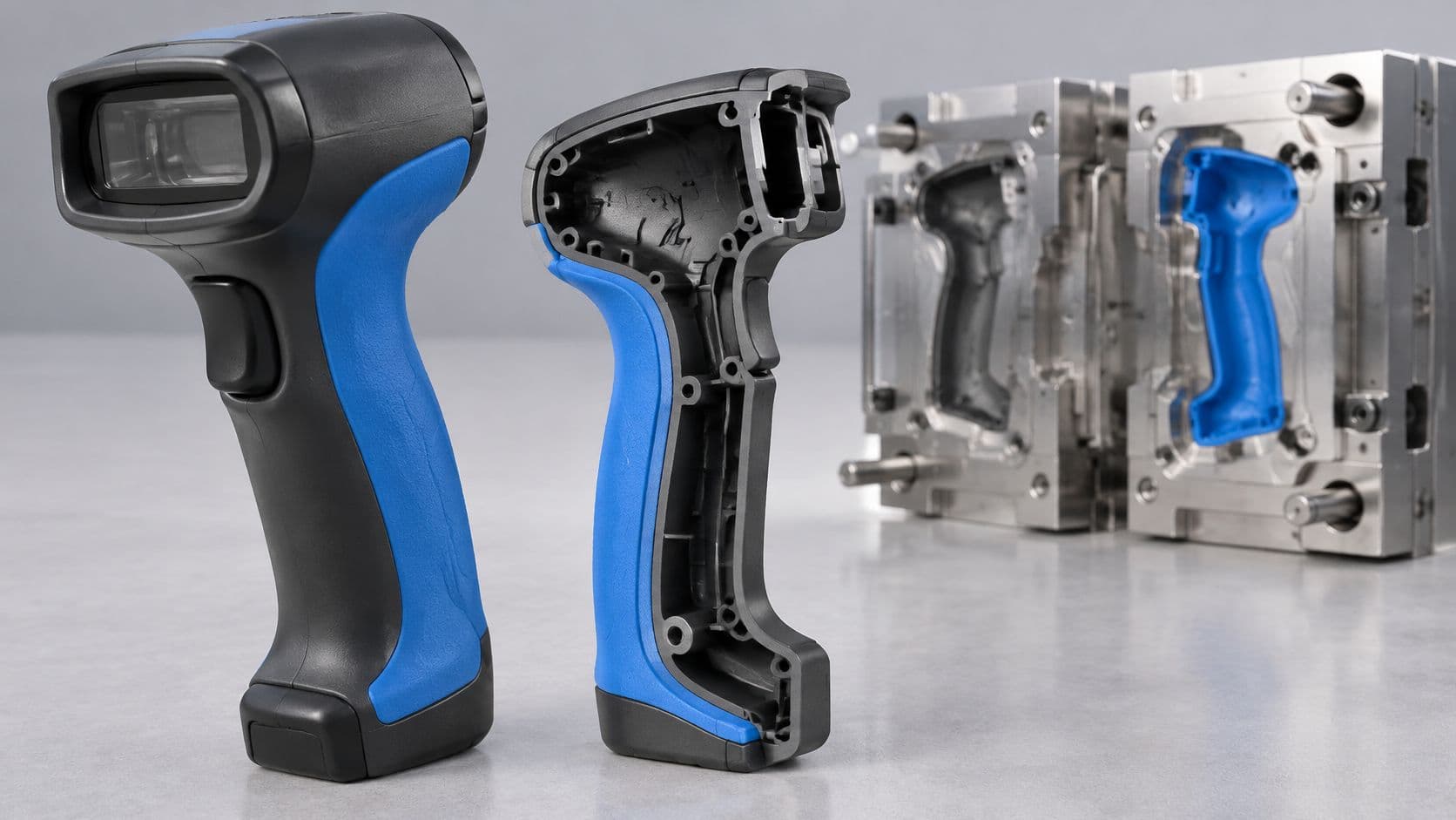
Adding a soft layer won't fix a housing that's already the wrong part. That's the advice teams get wrong most often with injection molding overmolding. A grip, seal, or strain relief molded over a rigid substrate only helps if you design the interface as carefully as the outside shape. If you don't, you've built a peel point into the part and locked it in steel.
Table of Contents
How Injection Molding Overmolding Builds One Part- Why the second cavity changes everything
Material Pairs and the Temperature That Makes Them Stick- Controls that keep the boundary alive
Wall Thickness Gates and Shutoffs That Hold the Insert- Process limits to design around
When a Stronger Bond Is the Wrong Target- Specify the failure mode instead
Process Evidence for Electronics Medical and Consumer Parts- Where those controls show up in real parts
Pick a Tooling Path and Send the Next Review- What to send for review
Why a Soft Layer Is Not Automatically Better
A rigid housing works fine on the bench. Then someone has to hold it with wet hands, drop it on a bench edge, wipe it with cleaner, or seal a cable where it leaves the enclosure. At that point the team reaches for a second part, a sleeve, a gasket, a pad, plus adhesive and an extra assembly station to put it all together.
That stack creates its own failures. You get a peel edge the user can lift with a thumbnail, tolerance stack-up between two separately molded parts, and a color or texture mismatch that's visible before the part ever fails. Adhesive adds a cure and a surface preparation you have to control every shift. The assembly looks simple in CAD because CAD doesn't show sweat, heat, or a cleaning wipe working under an edge for months.
What a glued-on grip can't give you
A handheld tool or phone grip that feels finished at first touch can still peel after heat, sweat, or cleaner exposure. The rigid core hasn't failed. The joint has. The soft material shrinks, flexes, and takes chemicals differently from the substrate, so stress concentrates exactly where the two materials meet. If that boundary was an afterthought, that's where the part lets go.
Treat the joint as the part. If the interface isn't on the drawing, it isn't designed.
Injection molding overmolding exists to remove the separate fastening and assembly operations by putting grip, sealing, insulation, cushioning, or appearance into one component. That's its value, not softness for its own sake. A seal that is molded in place doesn't need to be seated by an operator. A strain relief that is part of the housing doesn't get left off, glued crooked, or ordered from a second supplier.
But none of that is automatic. You're trading an assembly problem for an interface problem, and the interface problem is harder to inspect. You can't see wetting, interdiffusion, or residual stress on a finished grip. You can only design for them, process for them, and test for them after the environment has had a chance to open the joint.
So work through the decisions in order. How the shots are sequenced. Which material pairs can wet each other. Which geometry keeps the insert where you put it. When maximum bond strength is the wrong goal. How electronics, medical, and consumer parts get qualified with measured settings instead of a press-side pull test. If you stop treating overmolding as a cosmetic add-on, the rest of those choices get much clearer.
How Injection Molding Overmolding Builds One Part
Injection molding overmolding is a multi-material process in which a second polymer is injected over a previously molded substrate or a prefabricated insert, producing one integrated component. It isn't two parts fastened later. The second material is formed against the first material's surface, so that surface becomes part of the tooling problem and part of the product at the same time.
The sequence has three foundational stages in bi-component injection molding research describing substrate filling, core movement, and overmold filling. First, you fill and pack the substrate. Second, you switch the mold core, rotate the core, or retract an insert to create space for the second material. Third, you fill and pack the overmold into that new space.
Why the second cavity changes everything
Conventional single-material molding has no second interface to control. You fill one cavity, pack it, cool it, and eject it. Overmolding adds a moving boundary. The substrate has to survive being clamped again, heated again, and pushed by a new flow front without shifting, melting where it shouldn't, or sealing so poorly that the second shot flashes across a finished surface.
Think of it as pouring a rigid frame, then a flexible skin. The skin only works if it meets the frame while the surface can still be wetted and while the frame is held in exactly the right position. Substrate geometry, alignment, temperature, pressure, and material compatibility decide whether grip, sealing, insulation, cushioning, or appearance can replace assembly.
The route you choose determines how that second cavity is made and how much handling the substrate sees between shots.
| Route | How the second cavity is made | Typical substrate | Choose it when |
|---|---|---|---|
| Single-shot transfer | A finished substrate is placed into a second mold | Molded rigid plastic | You want a simpler tool and can control placement and preheat |
| Two-shot molding | The tool rotates or moves a core to open a new cavity in the same cycle | Rigid thermoplastic molded in the same tool | You need repeatable shot timing without manual transfers |
| Insert molding route | A prefabricated insert is loaded and the cavity closes around it | Metal insert or reinforced substrate | The first component isn't molded in that tool at all |
Sequential elastomer-on-thermoplastic molding isn't new. Elastomer over a polypropylene core was already a defined research topic more than 20 years ago in the work described in the reference above, which is why you shouldn't treat it as a novelty process. The motion that creates the second cavity is the decision you make first, because it drives alignment, cooling between shots, and how much labor touches the part.
Material Pairs and the Temperature That Makes Them Stick
A mechanical undercut won't save a pair that won't bond. Overmold adhesion is governed primarily by material chemistry and interface temperature, not by mechanical retention alone. A TPE and a rigid substrate stick when miscibility, polarity, and interfacial tension let the molten elastomer wet the surface and interdiffuse with it. If the chemistry is wrong, you're relying on hooks and holes to hold a skin that wants to peel.
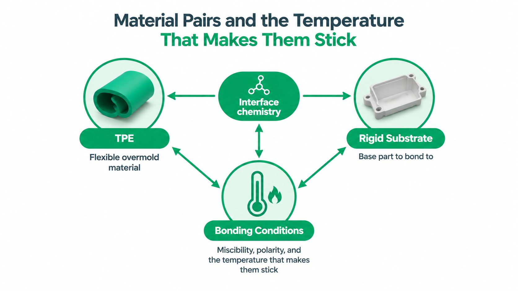
Polypropylene is the worked example worth studying. Research on PP overmolding indicates that mold design and sequential gate control may be required to keep the PP and copolymer boundary hot enough, because a cold interface can freeze the TPE before adequate wetting occurs and produce peel or delamination, as set out in Teknor Apex guidance on overmolding essentials and interface temperature. Cold is the enemy here, even when the resin pairing looks compatible on a chart.
Controls that keep the boundary alive
- Preheat the insert: A cold substrate pulls heat out of the flow front on contact.
- Cut the delay between shots: In two-shot molding, a long pause lets the substrate surface cool and skin over.
- Run the melt as hot as you safely can: Use the highest melt temperature that stays below substrate distortion and degradation limits.
- Protect surface cleanliness: Mold release, moisture, lubricants, fillers, and colorant carriers change surface energy and weaken the bond.
That last point gets missed in transfer routes. A substrate molded elsewhere, handled, bagged, and shipped arrives with a surface history you didn't specify. If you haven't defined handling and cleaning, you haven't defined the bonding surface.
Don't qualify adhesion only at the press. Test after thermal cycling, humidity exposure, and chemical contact, because differential shrinkage and residual stress can progressively open the interface. A grip that survives a pull on day one can still lift at an edge after repeated heating and cooling.
Treat the material pair, substrate temperature, gate location, and shot-to-shot timing as one coupled system. When you send a model for review, send a short pairing brief with it too, especially if you're still choosing between substrate families covered in our guide to injection molding thermoplastics. A generic request for soft-touch plastic gives the molder nothing to protect.
Wall Thickness Gates and Shutoffs That Hold the Insert
Chemistry decides whether bonding is possible. Geometry decides whether the melt gets there, packs out, and leaves the insert where you put it. Flow length, wall thickness, packing, and substrate restraint interact, and when they fight each other you get incomplete filling, sink, voids, flash, or an insert that has moved under pressure.
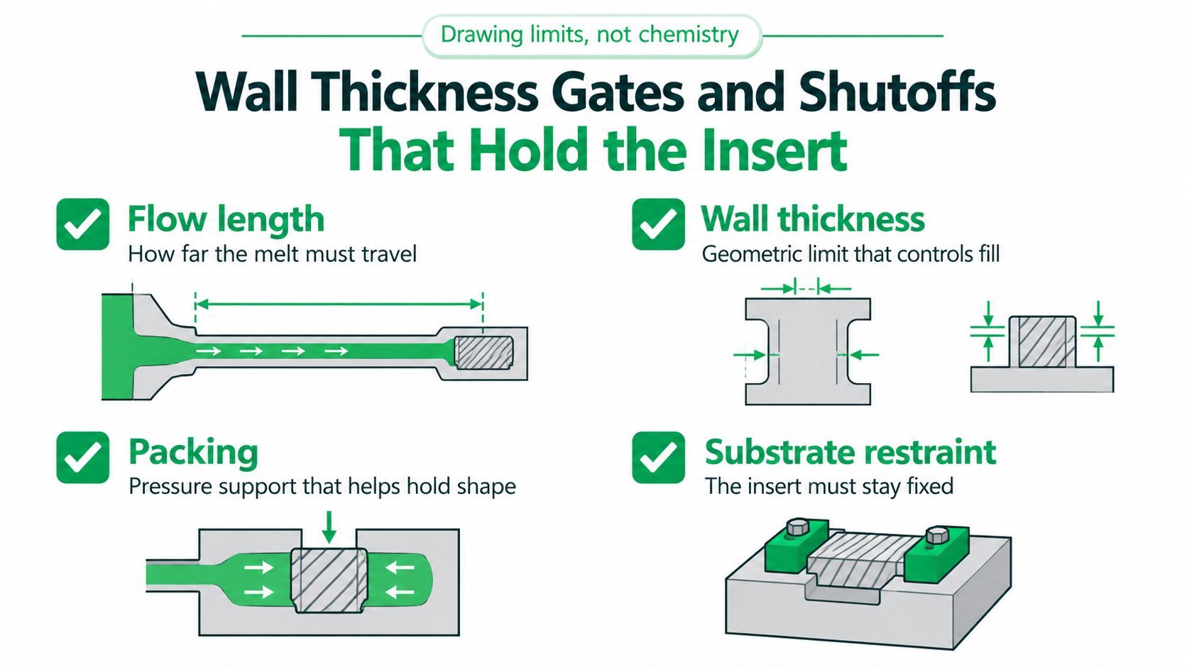
Start with the checks you can mark on a section view. A commercial TPE design guide identifies approximately 1.5 to 3.0 mm as a useful overmold wall-thickness range for many applications and recommends limiting flow length-to-thickness ratio to about 150 to 1 as an absolute maximum in Avient guidance on TPE overmold wall thickness and flow limits. Thinner walls and longer flow paths increase pressure loss and premature freeze-off risk, so a long, thin grip pad is a harder part than it looks.
Process limits to design around
Processing guidance in that same guide places TPE melt temperatures around 204 to 238°C, injection pressure often about 1.4 to 4.1 MPa, and a cavity fill of roughly 1 to 3 seconds to exploit shear-thinning and reduce hesitation defects. Materials requiring drying should be processed below approximately 0.1% moisture, since wet resin brings hydrolysis, splay, bubbles, and reduced interfacial quality.
Packing pressure and time must continue until gate freeze-off. Too little packing leaves volumetric shrinkage defects. Too much can distort or shift the insert. That is a narrow window when the substrate is thin, unsupported, or seated only by friction.
- Hard stops and shutoffs: Locate the insert mechanically so the flow front can't push it out of position.
- Uniform elastomer thickness: Avoid sharp transitions that starve one area and sink in another.
- Gate placement: Fill so the front doesn't hit an unsupported insert edge first and fold it over.
- Draft for both materials: A release that works for the rigid substrate can still drag the soft skin.
Practical rule: If the insert can move when you push it by hand in the open tool, it will move under injection pressure.
Put wall, gate, and shutoff notes on the section view before you request a tool quote. That habit aligns with the checks in our DFM guidance for injection molding, and it forces the conversation about restraint before steel is cut.
When a Stronger Bond Is the Wrong Target
Most guidance treats maximum adhesion as the goal. It shouldn't. The right target depends on what the part has to do across its whole life, including what happens when someone repairs it, separates it, or recycles it.
The shop habit of adding pressure makes this worse. Peer-reviewed research shows that adhesion can decrease unexpectedly when holding pressure and holding time increase, while higher melt temperature improves bonding, in research on controlled adhesion and debonding in PP copolymer overmolding. More pressure and longer packing don't reliably mean a better bond. If your corrective action for a peel failure is always to pack harder, you may be moving away from the fix.
Specify the failure mode instead
That same body of work shows PP and copolymer adhesion can be deliberately controlled through interface temperature and mold design, including localized areas intended to debond during recycling. That raises a question most drawings never answer. Should this part be permanently bonded everywhere, or should it combine durable zones with designed separation zones?
Pick one of these before you lock a process window:
- Cohesive failure: The elastomer tears within itself before the interface lets go.
- Adhesive failure: The boundary separates, which is a defect in most grip and seal zones.
- Peel resistance minimum: The edge must resist a defined lifting load in service.
- Controlled debonding: A defined zone separates cleanly for repair or material recovery.
A soft-grip housing or an insulated electrical cover makes the trade-off concrete. It has to stay bonded in the hand, through heat and flex. At end of life, a permanently inseparable mix of rigid substrate and elastomer can be difficult to separate cleanly, which matters more when a product is sold into markets with differing sustainability requirements.
Melt temperature, interface heating, contact time, crystallization, and mold geometry affect both service durability and recyclability. So don't put a single universal bond-strength number on the drawing. Map bonded zones and separation zones, name the required failure mode in each, and make the molder prove both.
Process Evidence for Electronics Medical and Consumer Parts
Material selection alone doesn't qualify a part. Measured settings do. A peer-reviewed polypropylene study used T-shaped specimens with an 80 mm by 80 mm by 2 mm base plate, a 70 mm by 63 mm by 2 mm overmolded rib, a nominal weld region of 60 mm by 2 mm, and 10 specimens per condition, as reported in polypropylene overmolding research using T-shaped specimens and defined melt temperatures.
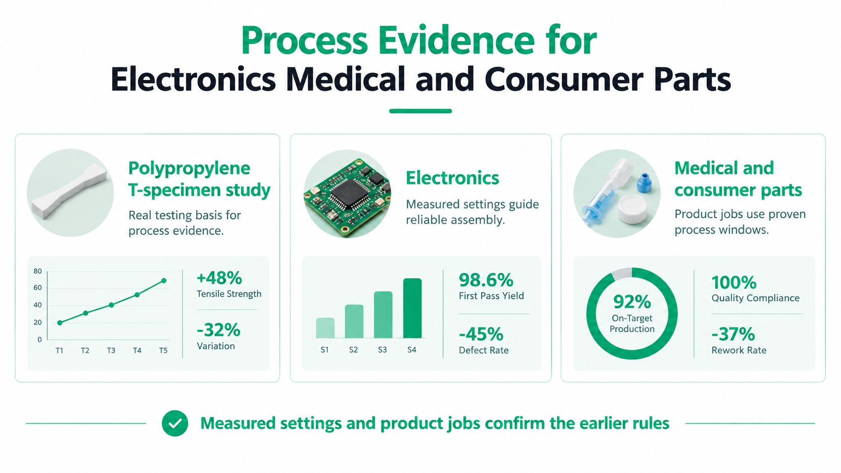
The tested window in that study covered melt temperatures of 190, 210, 230, and 250 °C, cooling water at 40 °C, a 5-second wait before injection, an injection rate of 30 cm³/s, a 50-bar pressure switchover, and a 7-second holding time. That is what a process window looks like when it's written down. Your part needs the same discipline, even if your numbers differ.
Optimization can move geometry as well as bond strength. In PFA injection overmolding of a metal insert, adjusting process factors reduced a shape-dissimilarity value from 0.04674 to 0.02573, a reported 44.95% improvement, in the research summarized with that specimen study. Micro-overmolding work adds a warning that mold temperature, melt temperature, injection speed, and insert alignment significantly affect critical dimensions, with alignment sometimes influencing dimensions more strongly than press settings.
Where those controls show up in real parts
Electronics housings use the soft layer as strain relief or electrical insulation. Insert alignment protects connectors and cable exits, and a small shift can close a clearance the assembly needs. Medical handhelds and seals need an interface that survives cleaning and humidity while the process stays traceable, which is why the requirements in our overview of injection molding for medical devices belong in the review early. Consumer grips are judged on feel, color match, and whether an edge lifts after daily flex, not on a lab-only bond number.
Build your test list from geometry, temperature, and alignment. Define the interface, control insert placement, and keep test evidence for the window you ran.
Pick a Tooling Path and Send the Next Review
Don't buy production tooling to answer a design question. Use rapid aluminum or soft tooling for a design-validation batch when the interface, gate, and failure mode are still moving. Move to a bridge tool for a pilot when the part is stable enough to test assembly and handling. Commit to a production tool only when the bonded zones, separation zones, and shutoffs have stopped changing.
Volume changes what you should watch. On a short run, insert loading and shot delay are easier to observe, and an operator can catch a substrate that arrives cold or contaminated. As volume grows, manual transfers become the variation you can't control, and two-shot rotation earns its cost by repeating the same interface timing without handling between shots.
What to send for review
- Section view: Substrate and overmold called out separately, with wall and flow-length notes.
- Failure mode by zone: Where the bond must be permanent and where separation is intended.
- Restraint features: Hard stops and shutoffs that locate the insert against the flow front.
- Test conditions: What the part must pass after heat, humidity, and chemical contact.
Finishing belongs in that package too. Gate trim, texture, and print are checks that the bond and shutoff survived handling, not independent cosmetic steps. A trimmed gate next to a lifted edge tells you the process window and the shutoff need attention before you approve appearance samples.
We offer low volume moulding, injection moulding prototyping, insert molding, overmolding, two-shot molding, and polycarbonate moulding, with injection molding solutions for low-volume production using rapid tooling and batch manufacturing. Our engineers suggest the optimal resin grade, Shore hardness, and mold strategy to meet functional and cosmetic requirements in the quote, so send the section view and the failure-mode map with your CAD rather than after it. That's the package that lets the first tool match the joint you need.
If you're preparing an overmolded grip, seal, or housing for tooling, send us your section view, material pair, and failure mode by zone and we'll review the mold strategy before you commit to production steel. Visit FIRMFG to start that review and get a quote built around the interface your part has to survive.