Undercuts in Injection Molding: Design Tips & Costs
You've got a clean part on the screen, the quote is live, and then DFM comes back with one ugly note, undercut. That's the moment every experienced manufacturing team recognizes, because the feature itself may be small, but the decision it forces is not. A simple geometry choice can turn into a tooling change, a labor step, or a redesign that saves money before steel is cut.
Table of Contents
- What Undercuts Are and Why They Matter
The real issue is not just geometry
Why DFM teams push back early
Types of Undercuts and Their Release Challenges- Internal, external, and side features
Tooling Mechanisms for Solving Undercuts- Mechanical choices and what they really do
The Economics of Undercut Decisions- Three paths, three different cost curves
DFM Best Practices for Undercut Design- Draft, texture, and parting-line discipline
Real-World Undercut Scenarios and Solutions
Your Undercut Decision Checklist
What Undercuts Are and Why They Matter
A design engineer opens a DFM report and sees the same problem flagged on two bosses, one snap tab, and a side hole that seemed harmless in CAD. The part looks fine on screen, but the mold doesn't care about the sketch. If a feature blocks straight-pull ejection from a simple two-plate mold, it becomes an undercut, and the tool has to change shape around the part instead of releasing it cleanly.
The real issue is not just geometry
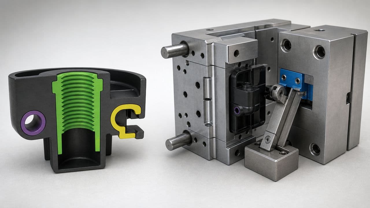
In plain terms, an undercut is any recess, slot, pocket, hook, or protrusion that keeps a part from being withdrawn straight out of a one-piece mold, and engineering references classify these features by geometry, direction, and volume because the same visible shape can behave differently depending on how the mold opens (Undercut definition and classification)). That matters because the fix is not always obvious. A feature that looks like a tiny notch in CAD may be fully locked into mold steel once the parting line is frozen.
Practical rule: if the feature is locked to the tool, draft alone won't save it. The mold architecture has to change.
The cost side is why experienced teams catch these issues early. Industry guidance notes that automated side-actions can add about 15% to 30% to base mold cost, with mid-complexity tooling commonly cited at roughly $3,000 to $6,000, while hand-loaded inserts may keep tooling cost lower but add about $0.50 to $2.00 per part in labor (tooling cost guidance). Those numbers explain why undercuts get flagged in DFM reviews long before tooling release. A small CAD decision can affect capital cost, cycle complexity, maintenance, and piece price all at once.
Why DFM teams push back early
The practical logic is simple. Changing a feature before steel is cut is cheap compared with reworking a mold after trials begin. Once the tool exists, every correction becomes slower, riskier, and more expensive, especially if the undercut has already driven you into slides, inserts, or lifters. That's why good DFM reviews don't treat undercuts as a styling preference, they treat them as a production-economics problem.
A part can still be moldable with an undercut, but the question is whether that undercut is worth the added complexity. On high-volume parts, the answer may be yes. On low-volume work, the wrong answer can lock you into tooling that never earns itself back.
Types of Undercuts and Their Release Challenges

The first thing I tell design teams is to stop thinking about undercuts as one category. An internal thread, a side hole, and an external snap hook may all be called undercuts, but they don't fail for the same reason and they don't deserve the same fix. The mold-opening direction, the location of the feature, and how much material sits around it all decide whether geometry alone can solve the problem.
Internal, external, and side features
Internal undercuts sit inside the part, such as recessed clips or threads. These are usually the most stubborn because the mold can't reach them from the outside without extra motion or a collapsing core. External undercuts appear on the outside of the part, where a parting-line move may sometimes eliminate them completely if the steel split can intersect the feature cleanly.
Side undercuts are the ones that force the tool to move perpendicular to the mold-opening direction. That's where slides and side-actions enter the conversation, because straight pull doesn't release them. Threaded features belong in their own bucket too, since they often need rotation or a collapsible release strategy rather than a simple ejector stroke.
The useful mental model is this. If the parting line can be moved to pass through the feature, the feature may stop being an undercut at all. If not, the mold needs a mechanical answer.
Why the same shape can demand different solutions
Engineering literature classifies undercuts by geometric entities, direction, and volume, and that classification matters because the same physical feature can require different release strategies depending on mold-opening direction (undercut classification)). A small hook on the outside of a housing may be a parting-line problem. The same hook placed inside a cavity becomes a tooling problem. That's why early CAD review matters more than late-stage debate.
The quick test is blunt. Ask whether the feature is geometrically locked to the mold steel. If the answer is yes, draft won't fix it. The tool needs a different architecture, or the part needs a different geometry.
| Undercut Type | Typical Location | Common Release Challenge | Geometry Fix Possible |
|---|---|---|---|
| Internal snap | Inside the part | Hidden from straight pull | Sometimes, rarely |
| External hook | Outside surface | Blocks ejection path | Often, by moving parting line |
| Side hole | Perpendicular wall | Needs cross motion | Sometimes, with redesign |
| Threaded feature | Internal or external | Needs rotational release | Usually not with draft alone |
Tooling Mechanisms for Solving Undercuts
When an undercut survives parting-line review, the moldmaker has to choose a release mechanism that matches the geometry instead of forcing one tool style onto every part. Cost, package space, and maintenance all appear at the same time. A mechanism that looks clean on paper can become expensive quickly if the part leaves no room for travel or if the resin does not tolerate the motion.
Mechanical choices and what they really do
Side-actions and slides move perpendicularly to the mold-opening direction, which is why they are the standard answer for external side features and holes. They need physical room for travel and enough part clearance for the core to move in and out cleanly (side-action guidance). Lifters work at an angle during ejection and suit some internal features and minor recesses, but they still depend on clean geometry and a controlled stroke.
Unscrewing cores fit parts defined by threads that need rotational release. Collapsible cores handle internal release by shrinking away from the part, which helps when a thread or internal detail has to come out without side motion. Hand-loaded inserts are the simplest to understand and often the easiest to justify for short runs, because an operator places the insert before each shot and removes it with the part after cooling.
For snap-fit style features, one source gives a practical release guideline of a 30° to 45° lead angle and enough part flexibility to deform elastically during ejection. That is not a magic number, but it is a useful filter. If the resin will not flex, the feature is more likely to scar, stick, or fail during release.
Practical rule: if the mechanism adds motion, ask what it adds in maintenance, not just what it adds in tooling.
One point often overlooked is that the “right” mechanism can change with production intent. A manual insert can be a smart answer in low-volume work, while the same geometry may justify a slide in production if the labor burden is too high. Teams evaluating those options can also compare them against LC Proto's injection molding services, especially when the part is still changing and the release strategy has not stabilized.
Undercut Tooling Solutions Comparison
| Mechanism Type | Complexity Level | Cost Impact | Best For | Key Constraint |
|---|---|---|---|---|
| Side-action or slide | Medium to high | Raises mold cost | External side features, side holes | Needs perpendicular travel space |
| Lifter | Medium | Adds mechanism complexity | Some internal recesses and clips | Requires angled travel and clearance |
| Collapsible core | High | Specialized tooling investment | Internal threads and recesses | More specialized, tighter design limits |
| Unscrewing core | High | Highest mechanical complexity | Threaded parts needing rotational release | Adds motion and cycle complexity |
| Hand-loaded insert | Low to medium | Lower tool cost, higher labor | Prototypes and low-volume parts | Manual handling and accessibility near parting line |
The Economics of Undercut Decisions
An undercut call is never just a tooling question. It is a cost question about how to ship acceptable parts at the required volume, with the least risk to schedule and scrap. The same feature can be a poor choice in a prototype tool and a sensible investment in a program that will run for a long time.
Three paths, three different cost curves
The first path is redesign. If the feature is not doing real work, removing it usually gives the cleanest mold and the lowest long-term risk. That is often the right answer when the undercut exists because a CAD shape was copied from a physical part without checking whether the function really needs it.
The second path is complex tooling. Side-actions, lifters, slides, and similar mechanisms make sense when the feature is required and the volume can absorb the added tooling burden. The earlier section covered the release mechanics, so the economic question becomes whether the part should stay exactly as drawn or change before steel is cut.
The third path is secondary operations. For prototyping and low-volume production, extra machining, hand work, or assembly steps can cost less than building a complex mold. That is why low-volume injection molding guidance often treats secondary operations as a practical bridge, not a compromise, especially when the design is still changing or the launch quantity is modest. The part gets out the door without committing to expensive tool motion that may never pay back.
Useful filter: if the part is still changing, do not pay for mold intelligence you may redesign out next month.
Picking the cheapest path that still works
The lowest-cost path is often the simplest one. A cleaner geometry with a manual step can beat a more elaborate tool, and an early redesign can beat both if the feature is not tied to function. That is the answer procurement teams need to hear, because a more elegant mold is not always a smarter purchase.
Use the part's life cycle to guide the choice. If the product is a short-run prototype or an early pilot build, flexibility usually matters more than sophistication. If the part is going into steady production and the feature is function-critical, a more complex release mechanism can be justified. If the feature is cosmetic or negotiable, redesign usually wins before anyone quotes steel.
| Decision Path | Best Economic Fit | What Usually Fails |
|---|---|---|
| Redesign away the undercut | Early concept, unstable design, cost-sensitive launch | Function gets over-preserved |
| Build complex tooling | Stable design, recurring high volume, critical feature | Tool cost outruns part value |
| Use secondary operations | Prototype and low-volume work | Labor can become the bottleneck |
DFM Best Practices for Undercut Design
Good undercut design starts with draft, but draft alone doesn't solve every release problem. The difference between a part that runs cleanly and one that scars in ejection often comes down to whether the designer treated the mold as a moving system instead of a static cavity. That's why the best DFM reviews focus on the steel path, not just the plastic shape.
Draft, texture, and parting-line discipline
A widely used guideline says to use 2° draft for exterior walls, 3° for interior walls and undercuts, and add 1° to 2° of draft for every 0.001 inch, or 0.025 mm, of texture depth on molded surfaces (draft-angle guidance). Those numbers show how tightly draft and surface finish are linked in real tooling. A textured face with weak draft is a common reason a part drags during ejection even when the undercut is small.
Moving the parting line is still the cleanest fix for some external undercuts. If the split can intersect the feature without breaking function, the undercut can disappear before the tool ever gets complicated. That's a geometry decision with tooling consequences, and it should happen while the CAD model is still cheap to change.
Flexibility and validation matter more than theory
Stripping undercuts only work when the material can flex enough to survive release. The same guide that discusses lead angles also points to a 30° to 45° lead angle and sufficient flexibility for elastic deformation, which is a reminder that geometry has to match resin behavior, not just screen geometry (lead-angle guidance). Stiff materials, fiber-filled grades, and awkward rib placement can turn a “simple” snap into a repeat scrap generator.
Prototype validation closes the loop. Teams should flex-test representative parts before committing to production tooling, especially for bump-off or stripping features. That isn't overcautious. It's the cheapest way to find out whether the part survives repeated ejection without whitening, cracking, or deformation.
Practical rule: validate with the real resin and a representative tool, not a hand sample that only proves the geometry looks good.
For teams building adjacent parts, LC Proto's plastic part guidance is useful because it keeps the design conversation tied to moldability rather than styling. The right question is never “Can I draw this?” It's “Can the mold release it repeatedly without paying for it twice?”
Real-World Undercut Scenarios and Solutions
A compact electronics enclosure came in with a pair of outside snap hooks. The first instinct was to add side-actions, but the parting line could be moved to catch the hooks cleanly, so the team redesigned the split instead. That eliminated a moving mechanism and kept the tool closer to a simple straight-pull layout.
A threaded medical component went the other way. The thread was function-critical, the design was stable, and the part needed repeatable release over sustained production. An unscrewing core made sense there because draft wasn't the problem, the thread itself was.
A consumer housing with side holes landed in the middle. The holes couldn't be moved into the parting line, and the volume justified more than a manual workaround, so slides were the practical answer. The team accepted the added mold complexity because it was cheaper than building labor into every unit.
A low-volume prototype took the opposite path. The undercut mattered, but the design was still evolving and the production run didn't justify a complex tool, so hand-loaded inserts kept the tooling simpler and the economics saner. That's the kind of case where secondary work is the right bridge, not a compromise.
Your Undercut Decision Checklist

A solid undercut decision starts with four questions. Does the feature need to exist, can the parting line absorb it, will the material flex enough to release it, and does the volume justify a mechanical tool feature or a manual operation? If you can't answer those cleanly, the design isn't ready for steel.
Use this checklist in every DFM review:
- Identify every locked feature: Scan the CAD for anything that blocks straight pull, including hooks, pockets, side holes, recesses, and threads.
- Classify the feature correctly: Internal, external, and side undercuts don't share the same fix.
- Try redesign first: Ask whether the function can survive without the undercut, or with a shifted parting line.
- Match the mechanism to the job: Use slides for side features, lifters for some internal details, and threaded release methods only when the feature requires them.
- Pressure-test the economics: Compare tooling complexity against secondary operations for the expected volume and timeline.
- Validate before hard tooling: Run prototype checks with the material and ejection strategy, especially on flexible or snap-fit parts.
If a feature forces the mold to become more complex, make sure that complexity is buying you something the market will pay for. That's the test. Talk to your toolmaker, challenge every undercut in CAD, and get a build recommendation before the design is frozen.
LC Proto supports teams that need to test undercut-heavy parts before committing to hard tooling, with injection molding, CNC prototyping, and low-to-mid volume production under one roof. If you're weighing redesign, slides, inserts, or a secondary operation for a part with undercuts in injection molding, visit LC Proto and bring the CAD file into the conversation early.