What Is a Deburrer? a Complete Guide for 2026
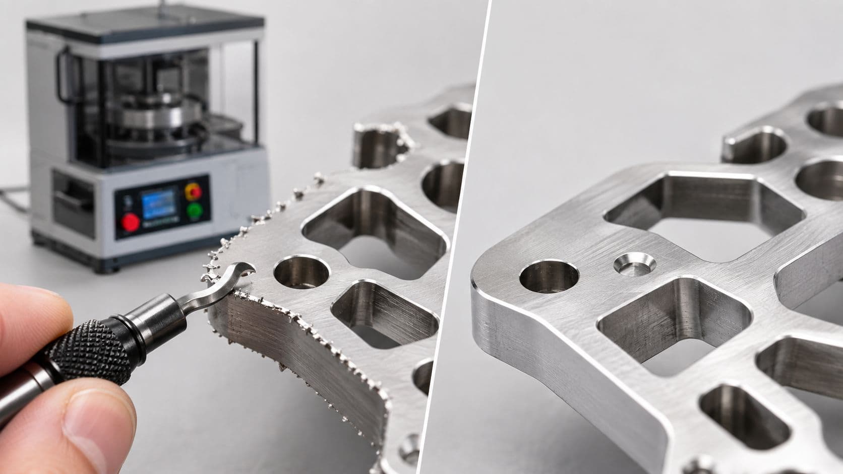
A deburrer is a tool or machine that removes burrs, the small raised edges, fins, or sharp protrusions left on a workpiece after machining, cutting, drilling, or molding. It's a secondary finishing operation that directly affects part safety, fit, and surface quality.
A prototype can look perfect in CAD and still arrive with sharp hole exits, ragged milled edges, or tiny slivers at stamped corners. That's where deburring stops being a cleanup step and becomes part of the manufacturing decision itself.
Table of Contents
Manual and Machine Deburring Methods Compared- Manual vs Machine Deburring Methods
Why Deburring Matters for Part Quality and Inspection- What burrs do to real parts
Choosing the Right Deburring Approach by Material and Volume- Start with the material
When Deburring Is the Wrong Move- Where over-deburring causes real damage
DFM Strategies to Minimize Burrs Before They Form- Design choices that reduce cleanup
Integrating Deburring Into Your Finishing and Quality Workflow- A practical checklist for engineers
Understanding What a Deburrer Actually Does
A fresh CNC-milled aluminum prototype is the kind of part that exposes burrs fast. The holes are clean, the geometry checks out, and then a finger catches on a sharp exit edge that shouldn't be there. That's the point where a deburrer earns its keep.

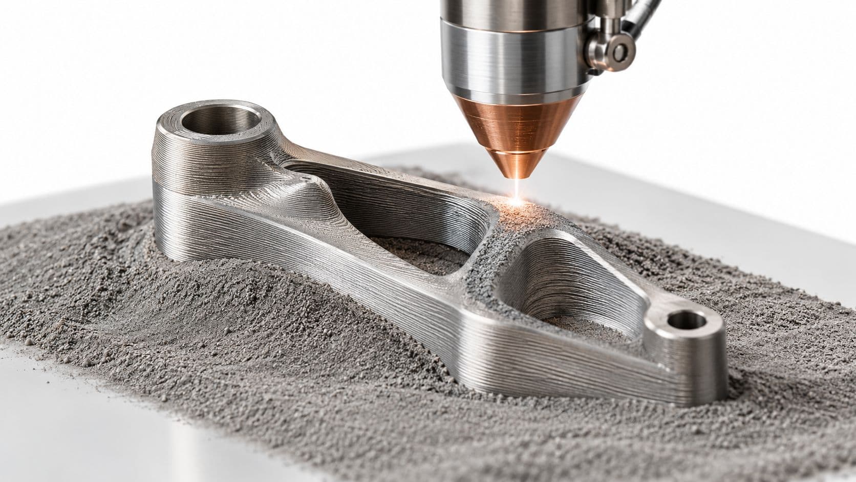
A deburrer is any tool or machine used in the deburring process, which removes burrs from a workpiece after a primary operation like milling, turning, drilling, stamping, grinding, cutting, or molding. Burrs are the small raised edges, fins, or sharp protrusions left behind when material is cut or displaced, and they're a normal byproduct of manufacturing, not a sign that someone necessarily did something wrong. The practical job of the deburrer is to turn a raw edge into a controlled edge.
Why it exists at all
Deburring is a secondary operation, which means it happens after the main machining or forming step. That distinction matters because the burr isn't part of the intended geometry, but it can still affect how the part handles, fits, and finishes. In the shop, the question isn't whether burrs can appear, it's how much edge control the part needs before it moves forward.
The history backs that up. The term “deburring” first appeared in English in 1943, and by the 1950s German engineers were measuring burrs, while manufacturers in the late 1950s to early 1960s were already using plastic media, centrifugal barrels, liquid compounds, and round vibratory machines for burr removal (Burr edge history)). That timeline shows deburring developed alongside precision production, not as an afterthought.
Practical rule: if a feature can't tolerate edge break, or if the edge is part of the function, deburring needs to be treated like a controlled process, not a casual touch-up.
A deburrer can be as simple as a hand file or as formal as a finishing machine. The tool changes, but the purpose doesn't. It removes unwanted edge material while protecting the part's usable shape.
Manual and Machine Deburring Methods Compared
A prototype with one stubborn exit burr is a different job from a production run with hundreds of parts leaving the same edge condition. Manual deburring handles that kind of one-off cleanup well. A technician can use a blade, scraper, stone, or file to target a single burr and leave nearby features alone, which matters on delicate geometry or small parts that do not belong in a machine cycle.
Machine deburring earns its place when repeatability and throughput matter more than hand control. Older rotary tumblers could take days or weeks to finish a burr-removal job, while newer vibrating tumblers could do in one day what rotary systems took weeks to accomplish. That shift changes how a shop plans labor, fixtures, and queue time. Once the part count rises, the question is no longer whether the burr can be removed, it is whether the process removes it consistently enough to keep downstream work moving.
Manual vs Machine Deburring Methods
| Method | Best For | Typical Speed | Limitations |
|---|---|---|---|
| Hand files, blades, scrapers | Prototypes, rework, isolated edges | Slow and operator-dependent | Inconsistent edges if technique varies |
| Vibratory tumbling | Small parts, batch finishing, broad edge softening | Fast for batches | Can affect all exposed edges, not just the one you care about |
| Centrifugal barrel finishing | Larger batch throughput, durable parts | Fast for batches | Not ideal for fragile geometry or features that need protection |
| Brush deburring machines | Sheet metal, edge conditioning, accessible faces | Faster than hand work | Brush contact can be too aggressive for fine features |
| Automated edge-breaking systems | Repeatable production parts | High throughput | Requires fixture planning and process setup |
Material and geometry decide which row of that table makes sense. Thin sheet can tolerate brush contact better than a fragile milled pocket, and a durable cast or machined part can survive batch finishing that would damage a precision edge on a lighter component. Volume matters just as much. A process that is easy to justify on a long run can be wasteful on a prototype, while a hand operation that works on five parts turns into a bottleneck on fifty.
History shows the tooling side has been responding to those trade-offs for a long time. Technical references note that the first commercial deburring tool went to market nearly a century ago, and E-Z Burr has supplied deburring solutions since 1960, including carbide tool expansions in the last 5 years for hard-to-machine materials and higher production volumes (technical source). Shops did not keep manual methods because they were elegant. They kept them because narrow jobs still call for local control, especially when the edge is part of the function and the rest of the part should stay untouched.
A practical selector starts with the edge, not the machine. If the part needs selective cleanup on one location, manual deburring is usually the safer choice. If the goal is consistent edge softening across a batch, machine deburring is usually the better fit. Surface finish targets also matter, and a surface roughness chart helps a team decide whether an edge treatment is likely to leave the part within the required finish range.
Manual work fits the edge that needs judgment. Machines fit the batch that needs repetition.
The best shops use both, but they do not use both for the same reason. Manual deburring handles exceptions, rework, and geometry that does not tolerate broad contact. Machine deburring handles the parts that can justify setup time and need a stable, repeatable edge condition.
Why Deburring Matters for Part Quality and Inspection
Burrs aren't just a cosmetic defect. They interfere with how parts meet, seal, and survive handling, and they can turn an otherwise good part into an assembly problem. A burr on a mating edge can change fit. A burr on a sealing face can compromise performance. A burr on a sharp corner can turn into a safety issue.
The inspection side is just as important. Deburring is tied to edge-break requirements, and one fabrication guideline calls for edges to be broken to a maximum of 0.015 in. when drawings don't specify otherwise (deburring machines reference). That makes deburring measurable, not subjective. If the print is silent, the shop still has to decide what “acceptable” means.

What burrs do to real parts
A burr can interfere with assembly because the part no longer seats the way the model intended. It can also damage downstream finishes, especially where edges take more coating buildup or scratch adjacent surfaces during handling. In regulated or high-reliability work, those are not cosmetic nuisances, they're process failures.
Surface finish specs matter too. Deburring and roughness are related but not identical. If your team is already defining Ra and Rz targets, the edge condition needs to line up with the rest of the finishing plan, which is why surface-roughness references are worth keeping close during design and inspection planning, including this surface roughness chart.
Burr control belongs in the same conversation as inspection, because inspectors don't evaluate a part in pieces. They evaluate the whole surface condition and the way edges behave in use.
Deburring also affects how parts move through the rest of the finishing chain. A sharp edge can trap coating, create inconsistent thickness, or chip during handling. When the edge is managed early, the downstream process gets more predictable.
Choosing the Right Deburring Approach by Material and Volume
A deburrer for a cut copper pipe, a CNC-milled aluminum prototype, and an injection-molded plastic enclosure won't be the same tool, and it shouldn't be. Material behavior, geometry, and quantity shape the process more than the word “deburr” does. That's where generic advice usually falls apart.
Start with the material
Ductile metals like aluminum and copper tend to form burrs that smear or hang on. Harder materials may produce smaller burrs, but they can also leave sharper edges that need more controlled removal. Plastics add another layer of risk because heat, surface tearing, or overcutting can change the part more than the burr itself.
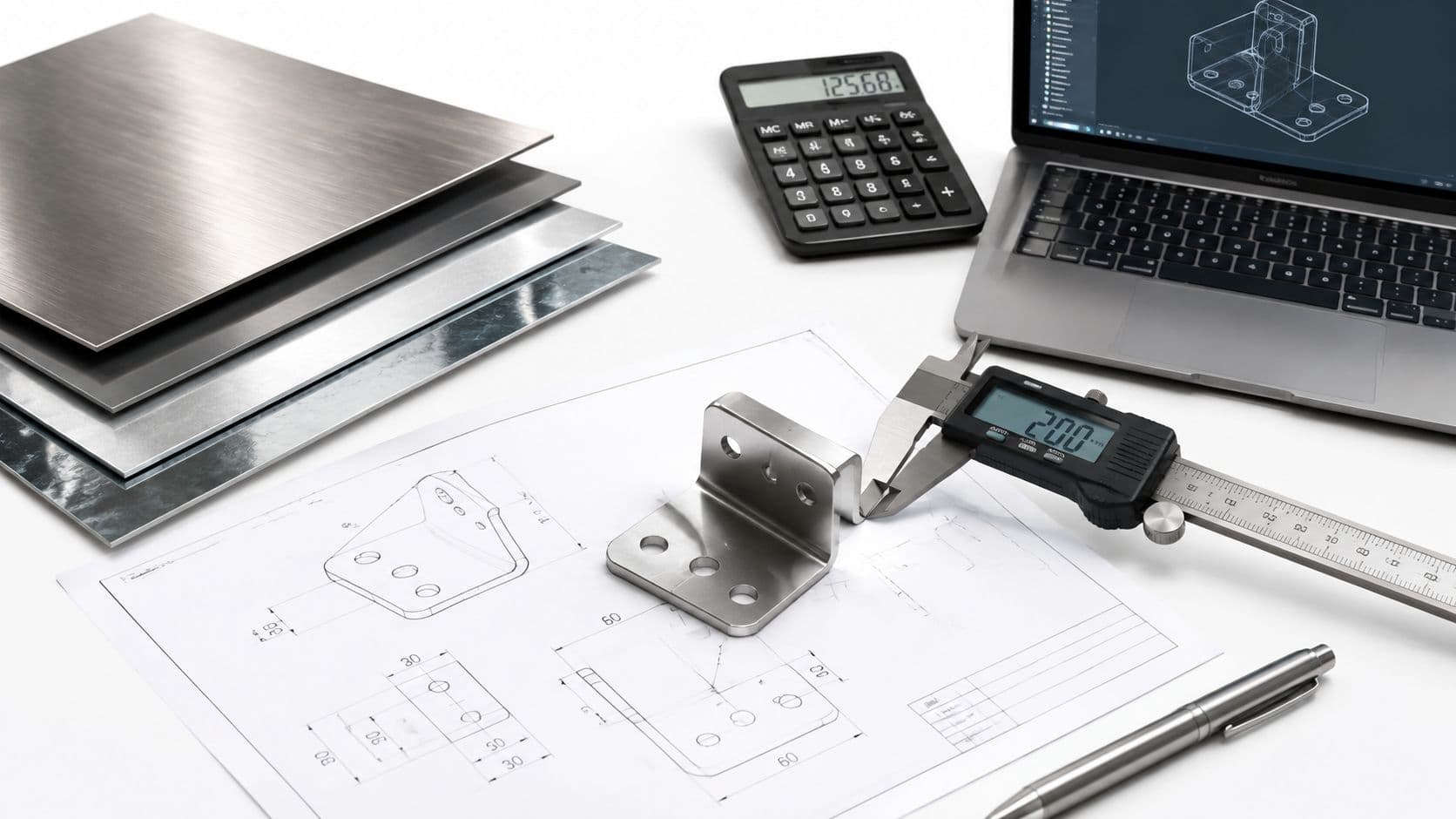
Sheet metal often favors brush-based edge conditioning when the part shape is open and accessible. The technical example in the verified data shows brush-based deburring machines rated at 1.5 kW, 2,840 rpm, and capacities up to 90 × 90 mm cross-section, while high-speed plate deburrers can use 2.6 kW and 6,700 rpm idle speed with bevel geometry up to 15 mm at 30°, 45°, or 60° (machine specifications). Those numbers show how strongly the process is tied to geometry and edge control.
Then match the volume
One-off prototypes usually justify hand deburring because setup overhead would be wasteful. Small batches can go either way, depending on repeatability and part access. Production parts, especially when the quantity starts to justify fixture design, usually need a machine process or a toolpath strategy that bakes edge treatment into the cycle.
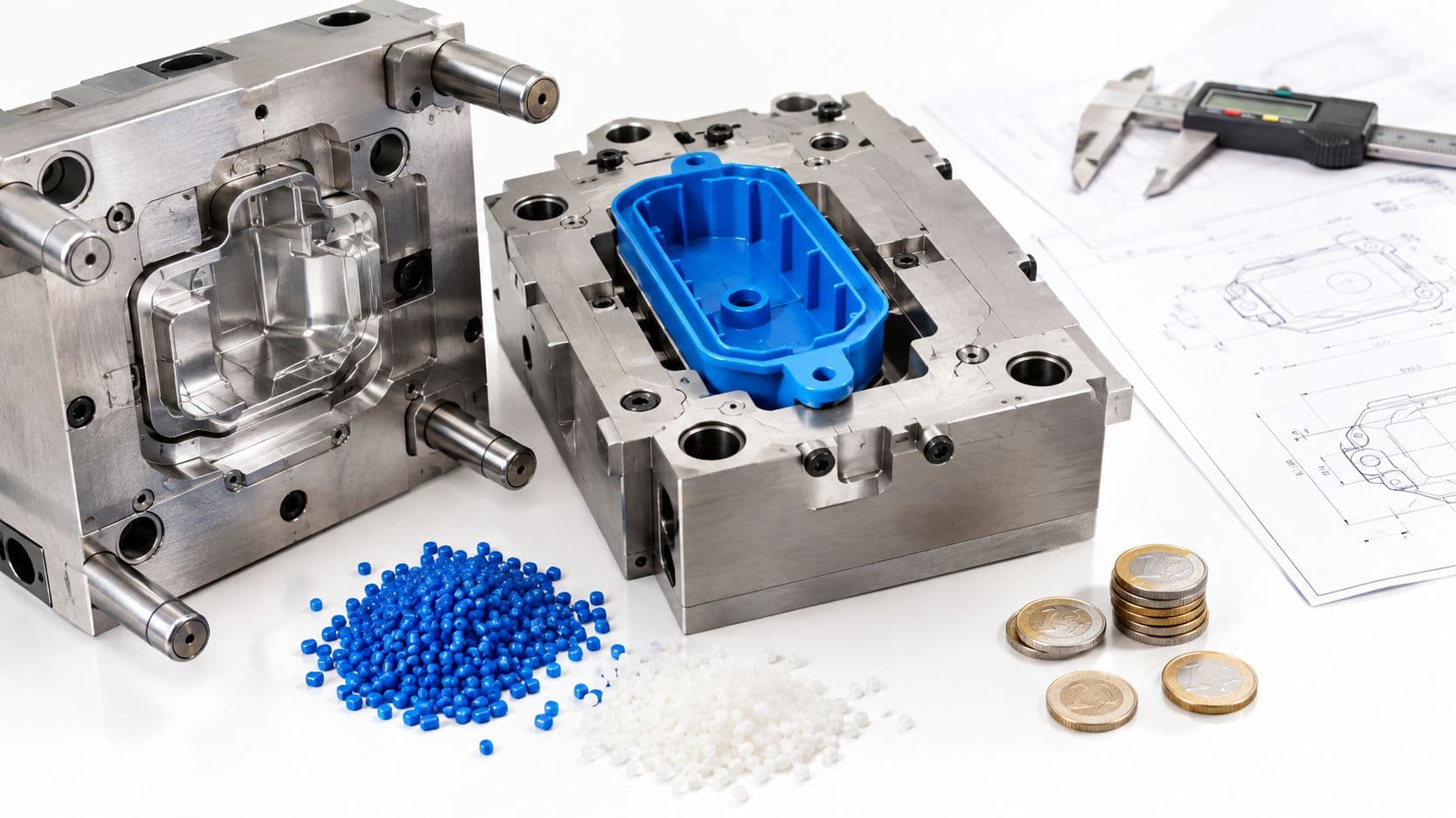
The material route matters too. A broad manufacturing source notes that deburring applies to metals, plastics, rubber, and composites, and can be mechanical, thermal, or chemical depending on the part's needs (deburring methods overview). That matters because the same edge issue on a molded enclosure and a machined bracket may need completely different removal strategies.
A good process choice removes only what the drawing can afford to lose.
For teams comparing options, LC Proto offers CNC machining, sheet metal fabrication, injection molding, vacuum casting, and surface finishing, so the deburring approach can be matched to the part route rather than forced onto every job the same way. The practical benefit is simple, the more closely the edge treatment follows the manufacturing method, the fewer surprises show up at inspection and assembly.
When Deburring Is the Wrong Move
Deburring is not always the right correction. On precision parts, the wrong edge-removal method can damage fit, change tolerance, or alter a surface that was meant to stay sharp. That's why experienced engineers treat deburring as a decision, not an assumption.
Where over-deburring causes real damage
Tight-tolerance bores are the obvious caution. If a burr is pulled too aggressively, the cutter can remove material where the part needs its diameter preserved. Sealing surfaces are another risk, because rounding the edge can change how gaskets, O-rings, or adjacent faces behave in assembly.
There's also the press-fit problem. Some edges need to stay crisp so they engage properly with a mating feature. If a deburrer softens that corner too much, the fit can loosen or the assembly can become inconsistent across parts. That's not cosmetic drift, it's a functional change.
The more complex the geometry, the higher the risk of collateral removal. Thin walls, internal features, and inaccessible pockets don't give much margin for a general-purpose finishing pass. In short-run work, that risk is even harder to hide because there isn't enough volume to absorb rework.
If an edge is part of the design intent, don't let a generic deburring step erase it.
That's why edge-break requirements belong on the drawing when the function depends on them. It's also why the method matters. Manual work can protect a critical feature better than a machine on one part, while a machining-strategy approach can be better than any post-process on another.
The key question is whether the burr should be removed after the fact or prevented by the process route in the first place. On critical features, that's often the better conversation to have with the machinist before the job runs.
DFM Strategies to Minimize Burrs Before They Form
The easiest burr to remove is the one that never forms. That's not theory, it's practical design work. When a part gets burr-prone geometry, the shop has to spend time undoing what the print asked the machine to create.
Design choices that reduce cleanup
Sharp internal corners are a common source of trouble. Where the function allows it, a radius or chamfer gives the cutting tool a cleaner path and leaves less ragged material behind. Hole exits deserve the same attention, because burrs often build at the breakout side when the tool exits the material.
Tool access matters more than many design teams expect. If the cutter can't reach an edge cleanly, the shop may be forced into a secondary deburring pass that adds cost and variability. The better option is to direct burr formation toward accessible areas and to avoid creating a geometry that traps the burr inside a pocket.
Material choice also shapes the burr profile. Ductile materials generally need more cleanup than brittle ones, which may chip instead of forming long, difficult burrs. That doesn't make brittle materials easier overall, it just changes the failure mode.
The most effective DFM conversations happen early, during quoting and review, when the part can still be adjusted without rework. LC Proto's design for manufacturability guidance fits that logic, because burr-prone details are easier to fix in CAD than at the bench.

The cheapest deburring plan is a cleaner part design.
That doesn't mean every burr can be designed away. It means the print should make the unavoidable burrs easy to reach and cheap to remove.
Integrating Deburring Into Your Finishing and Quality Workflow
A good deburring plan sits inside a larger workflow. The usual sequence is primary machining or forming, then deburring, then any additional surface finishing, then final inspection. If one step is sloppy, the next one inherits the problem.
Surface finishing and deburring often overlap, but they're not the same thing. A part can be deburred and still need coating, blasting, polishing, or texture control. LC Proto's surface finishing options fit into that same chain, because the edge condition needs to support the final appearance and function instead of fighting it.
A practical checklist for engineers
- Call out edge conditions on the drawing: If a specific edge must stay sharp, say so. If an edge must be broken, specify it clearly.
- Match the process to the material: Don't use the same removal approach for aluminum, sheet metal, and molded plastics.
- Plan for inspection: Deburred edges need to be checked alongside dimensional features, not after the fact.
- Coordinate with finishing: Anodizing, coating, and plating all react differently to edge condition.
- Choose the right production route: Prototype, small batch, and production parts usually justify different deburring choices.
The best workflow is the one that leaves no ambiguity between machining, finishing, and inspection.
For teams sourcing finished parts, look for a partner that can carry the part from quoting through shipment with process control, dimensional inspection, and documented checkpoints. That's especially important when tolerances, appearance, and assembly all have to land together.
If you're working on a prototype, short run, or production part that needs controlled edge removal, LC Proto can help align CNC machining, sheet metal, molding, and finishing so burr control is handled as part of the process, not a last-minute fix. Visit LC Proto to review your drawings, discuss edge requirements, and choose a manufacturing route that fits your part.