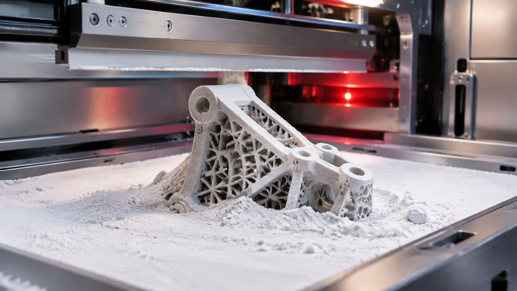
Surface Roughness Chart Guide for Engineers
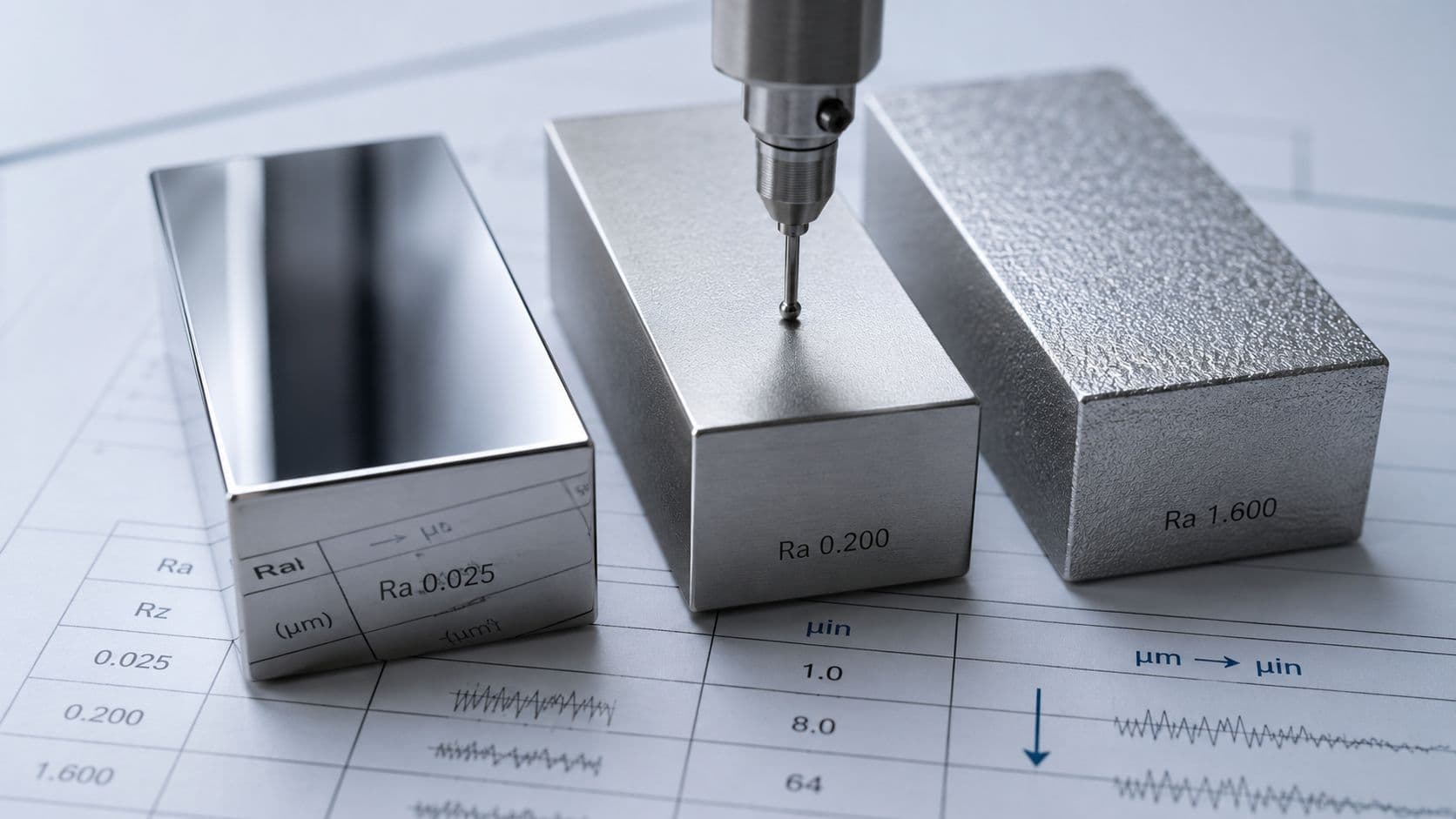
You're staring at a drawing, the tolerance stack looks fine, and then somebody asks the question that always comes too late, “What finish do we want on this face?” If you leave that blank, the shop guesses, the inspector negotiates, and the part often comes back with a surface that's technically machined but functionally wrong. A surface roughness chart closes that gap by turning a visual expectation into a measurable requirement that both design and manufacturing can live with.
The value is not the chart itself, it's the contract behind it. A good callout helps a team standardize language, match the process to the finish, decide how to inspect it, and protect the part's function, whether that function is sealing, sliding, or looking right on the bench. That's why a finish note belongs next to the geometry, not buried as a cosmetic afterthought.

Table of Contents
- Why a Surface Roughness Chart Matters on Every Drawing
- Ra, Rz, and Rt Explained in Plain Language
Ra is the everyday starting point
Rz and Rt catch the outliers
Pick the metric based on function
The Surface Roughness Chart Reference Table- Standard Surface Roughness Reference Table
How to Read a Surface Finish Symbol on a Drawing- Read the symbol from the top down
Achievable Roughness by Manufacturing Process- Compare the process families against the finish
How to Measure and Inspect Surface Roughness- Use the right cutoff and length
When a Lower Ra Number Is Not Actually Better
Specifying Ra and Rz on Drawings for FIRMFG- Write the callout like this
Ra vs Rz vs CLA vs RMS Conversion Reference- Use conversion carefully
Quick Reference Checklist for Surface Roughness Calls
Why a Surface Roughness Chart Matters on Every Drawing
A missing finish note looks harmless until the part reaches the floor. One supplier makes a perfectly reasonable assumption about a cosmetic face, another holds a sealing face to a tighter target than necessary, and a third asks for clarification because the drawing says “smooth” but nothing else. That's how a simple omission turns into rework, delayed release, or a rejected lot.
The historical reason charts matter is standardization. ASME B46.1 defines Ra as the arithmetic average of the absolute profile height deviations from the mean line over a defined evaluation length, and that definition gave the industry a shared language for roughness callouts. In practice, it made Ra 125 µin (3.2 µm) the common “standard as-machined finish,” while 32 µin (0.8 µm) became a much finer benchmark and 15 µin (0.38 µm) the finest finish designation defined in ASME BPE, all of which are easier to use than vague visual descriptions surface roughness average reference.
Practical rule: if the surface affects sealing, sliding, or appearance, it needs a roughness callout, not a guess.
A chart also does four jobs at once. It standardizes language across teams, maps a process to what it can realistically produce, guides inspection, and protects function by tying a number to a use case rather than to appearance alone. The imperial and metric worlds line up more easily than many drawings suggest, because 1 µm is about 40 µin surface roughness average reference.
A good drawing callout is not a finishing footnote. It's a specification boundary, and the shop can only quote against it cleanly when the roughness target is explicit.
Ra, Rz, and Rt Explained in Plain Language
Ra is the everyday starting point
Ra is the arithmetic average roughness. It tells you, on average, how far the profile deviates from the mean line, which is why it shows up so often on general machining drawings and procurement notes ASME B46.1 roughness reference. For many parts, that's enough, especially when the goal is a broad finish band rather than a narrow functional risk.
That said, Ra is an average. A surface can look acceptable on an Ra callout and still hide a burr, scratch, or isolated peak that matters in service.
Rz and Rt catch the outliers
Rz is more sensitive to the deeper valleys and taller peaks in the profile, so it's often the better choice when function depends on outliers, wear, sealing, or contact behavior surface roughness guide. Rt is the maximum peak-to-valley height across the evaluation length, which makes it useful when a single defect can ruin a seal or create a cosmetic reject.
A part that seals against a gasket cares less about average texture than about the worst local defect in the contact band.
A simple way to choose the parameter is to match it to the failure mode. For a sliding fit, Ra is often the first screen, but Rz becomes more informative if galling or wear is the concern. For an O-ring groove or a bearing seat, Rz or Rt can reveal an extreme feature that Ra hides. For a cosmetic face, Ra describes the overall texture, while Rt helps catch a scratch that would jump out after assembly.
Pick the metric based on function
The cleanest drawings name the parameter, the target value, and the measurement conditions. That's the point of the standard language, whether the note follows ASME B46.1 or the ISO measurement approach described in current roughness guides measurement guidance. A single number is rarely the whole story, and the wrong parameter often creates more trouble than the wrong finish.
The Surface Roughness Chart Reference Table
A surface roughness chart becomes useful when it stops being decorative and starts linking a grade to a process and a function. The table below is the practical shorthand most engineers keep open while they're checking a drawing or setting up an RFQ. The grade letters below follow the common N-scale mapping used in machining references, where N6 lines up with 0.8 µm Ra, N7 with 1.6 µm Ra, and N8 with 3.2 µm Ra surface finish chart reference.
Standard Surface Roughness Reference Table
| Grade (N) | Ra (µm) | Ra (µin) | Typical Rz (µm) | Typical Use |
|---|---|---|---|---|
| N5 | 0.4 | 16 | 2.5 to 4 | Fine sealing faces, precision sliding, polished technical surfaces |
| N6 | 0.8 | 32 | 4.5 to 6.5 | Good sealing surfaces, light sliding fits, tighter cosmetic faces |
| N7 | 1.6 | 63 | 8 to 10 | General CNC finish for functional faces, assemblies, and machined housings |
| N8 | 3.2 | 125 | 12 to 20 | Standard as-machined finish, many non-critical machined parts |
| N9 | 6.3 | 250 | 25 to 40 | Rougher machined faces, secondary surfaces, brackets |
| N10 | 12.5 | 500 | 50 to 80 | Rough machining, early-stage stock removal |
| N11 | 25 | 1000 | 100 to 160 | Very rough surfaces, limited direct functional use |
| N12 | 50 | 2000 | 200 to 320 | Extremely rough, typically not a finished functional surface |
The most important unit relationship is still the simplest one. 1 µm is about 40 µin, so a drawing can move between metric and imperial without changing the roughness meaning surface roughness average reference.
For design work, the table is less about memorization and more about intent. N8 is usually fine when the face is not sealing or sliding. N7 starts to matter when the surface interacts with another part. N6 is where many teams begin to care about leakage risk, mating feel, or a cleaner visual finish. The wrong choice usually isn't the one that looks worst on paper, it's the one that doesn't match the function.
How to Read a Surface Finish Symbol on a Drawing

An ISO-style finish symbol is only useful if you can read every field, not just the value. The basic check mark shape tells you the surface is controlled, and the added fields tell you how it's controlled. For drawing work, the common references are ISO 1302 and ASME Y14.36M, and the whole point is to stop the supplier from guessing.
Read the symbol from the top down
Start with the parameter, usually Ra or Rz. Then read the required value, which might be 0.8 µm or 32 µin depending on the drawing system. If the note includes a cutoff length or sampling length, that matters because it changes the measured result. If the drawing specifies a manufacturing method, that's a process constraint, not just a finish target.
The finish symbol is not decoration. It's a compact instruction set for manufacturing and inspection.
A common mistake is writing only a value, such as “0.8,” with no parameter. That forces the supplier to guess whether the number means Ra, Rz, CLA, or something else entirely. The better callout names the parameter, the value, and the measurement standard or conditions, which is exactly what portable drawings need surface roughness guide.
A simple annotated reading order
- Parameter slot. Ra, Rz, or another explicit metric.
- Value slot. The target roughness number.
- Cutoff or sampling length. Include it when the default won't work.
- Method or process note. Add only when the process matters.
- Machining allowance. Use this when the drawing expects stock to be removed later.
Surface finish symbol details are only meaningful when the drawing uses them consistently. If the callout is tied to a sealing face, a bearing seat, or a cosmetic panel, the symbol should make that function obvious to the shop and the inspector.
Achievable Roughness by Manufacturing Process
A finish target only works if the process can hit it. The practical question is not “What does the chart say?” but “Which route gives me that texture without extra rescue work?” In machining references, standard CNC work often lands around Ra 1.6 to 3.2 µm, fine turning can reach 0.4 to 1.6 µm, grinding can reach about 0.4 µm or lower, and polishing or lapping can move down to 0.1 µm and 0.05 µm respectively process capability chart.
Compare the process families against the finish
| Process family | As-built roughness tendency | Better finish with post-processing | What usually drives the result |
|---|---|---|---|
| CNC milling and turning | Tool marks and feed lines, often around the general machined band | Smoother after fine finishing, careful tool selection, or secondary finishing | Tool geometry, feed, chatter, step-over |
| SLA 3D printing | Layer or scan texture is visible, especially on broad faces | Better after sanding, coating, or polishing | Layer resolution, support marks |
| SLS 3D printing | Grainy, matte texture is common | Better after bead blasting or coating | Powder fusion texture, porosity on the skin |
| Injection molding | Can produce clean cosmetic surfaces when the tool finish is right | Improved further with mold polish or texture control | Mold surface, knit lines, gate location |
| Vacuum casting | Often shows the replica character of the master and the mold surface | Improved through finishing of the master and post-finish on parts | Master quality, silicone tool condition |
| Sheet metal fabrication | Bends, shear marks, and brushed texture often define the face | Better after bead blasting, polishing, or surface treatment | Cut edges, forming marks, brush direction |
The rule of thumb is simple. If the drawing asks for a tighter finish, choose the process that naturally gets closest before you add finishing. CNC is a strong choice for functional metal faces. Molding wins when a repeatable cosmetic finish matters. Additive processes are useful for speed and geometry, but they usually need post-processing when the face has to look or seal like a machined part.
How to Measure and Inspect Surface Roughness
A number on a report is only as good as the setup behind it. A contact stylus profilometer is still the workhorse for many shop-floor checks, while optical methods are better when the surface is delicate or the feature is too fine for a stylus to read cleanly. Before anyone signs off the part, the surface should be clean, the instrument calibrated, and the measurement setup matched to the expected finish measurement guide.
Use the right cutoff and length
ISO 4288 guidance commonly links cutoff selection to roughness range, and a 0.8 mm cutoff is a standard workshop default for most machined surfaces in the Ra 0.1 to 2 µm band measurement guide. Longer cutoffs are used as surfaces get rougher. That matters because the filter choice can shift the reported result even when the part itself hasn't changed.
A practical inspection workflow
- Select the instrument. Use a profilometer for validated roughness numbers, or optical measurement when contact would distort the surface.
- Set the parameters. Confirm cutoff, sampling length, and the metric being reported.
- Prepare the surface. Clean oil, chips, and residue before reading.
- Measure in the right direction. The lay matters, so the trace has to cross the texture correctly.
- Record the condition. Calibration state and measurement standard should stay with the report.
For tight-tolerance prototypes and production parts, a documented measurement workflow is the only defensible path. That's where dimensional inspection systems such as CMM and scanning come into play, especially when the roughness claim is tied to a released drawing rather than a shop estimate. CMM inspection services are the right kind of evidence when acceptance can't depend on a handheld comparator.
A comparator is fine for a quick check. A profilometer report is mandatory when the finish is part of the acceptance criteria.
When a Lower Ra Number Is Not Actually Better
The instinct to drive every number down can backfire. A lower Ra can come from a different filter, a different cutoff, or a different sampling length, not from a better surface. That's why two labs can report different answers on the same part if they don't measure with the same setup measurement guidance.
The deeper issue is functional blindness. A surface can look “better” on Ra and still carry one deep scratch, burr, or valley that matters for sealing, wear, or local stress. That's why Rz is often the better screen when a function depends on peaks and valleys rather than on the average profile roughness chart gap analysis.
For a bearing seat, the problem is not just average texture, it's the occasional defect that can interrupt contact. For an O-ring groove, a single local imperfection can create a leak path. For a cosmetic cover, Ra may look great on paper, but Rt is what catches the scratch that a customer sees the moment the part hits the light.
The practical lesson is to stop worshipping the lowest number. Pick the metric that matches the failure mode, then lock down the measurement conditions so the reported value means what the drawing says it means.
Specifying Ra and Rz on Drawings for FIRMFG
A good DFM note is short, explicit, and hard to misread. Put the parameter, the target value, and the measurement standard or conditions on the drawing. Leave out vague phrases like “smooth,” “finish to match,” or “as machined” unless they're backed by a roughness target, because those phrases invite disagreement instead of acceptance.
Write the callout like this
- Functional face, sealing. Name the face, specify Rz or Ra, and include the cutoff or standard if it matters.
- General machined face. Use Ra when the goal is a predictable production finish, not an ultra-tight texture.
- Cosmetic face. Add the finish target only where the customer will see it, not on every edge of the part.
- Inspection note. State the measurement method so the report matches the drawing.
A well-written drawing also avoids over-specifying noncritical faces. If only one land seals, only that land should carry the finish requirement. If a plastic enclosure has a visible outer shell and hidden internal ribs, the callout should target the visible shell and leave the ribs alone unless function demands otherwise.
Stainless steel finish guidance is especially useful when the part mixes appearance and function, because one finish note rarely fits every face on the same part. The same logic applies to metal, molded plastic, and printed prototypes. Finish where the function lives, and don't pay for precision on geometry that doesn't need it.
Ra vs Rz vs CLA vs RMS Conversion Reference
Legacy drawings still show CLA and RMS, while newer ones usually prefer Ra and Rz. The rough conversion references are only starting points, not equivalences. Published references show CLA ≈ Ra × 40 and Rz ≈ Ra × 7.2 to 7.6, depending on the convention used conversion reference.
That means a conversion can help you orient yourself, but it can't always settle acceptance. The same drawing value can mean different things if one lab uses a different filter or cutoff. When the finish is critical to function, remeasure the part in the target parameter instead of converting a legacy number and hoping it lands in the same place.
Use conversion carefully
- Imperial legacy callouts. Translate them for discussion, but confirm them by measurement before final approval.
- Metric production drawings. Prefer direct Ra or Rz specification with clear conditions.
- Critical sealing or wear features. Remeasure in the function-relevant metric.
- Procurement handoff. Treat converted numbers as guidance, not final acceptance language.
If the finish is only for a visual comparison, a conversion may be enough to start a conversation. If the finish affects sealing, wear, or contact, a fresh measurement is the safer path.
Quick Reference Checklist for Surface Roughness Calls
Keep this near the CAD station or inspection bench:
- 0.4 µm Ra, 16 µin. Fine sealing or sliding surfaces.
- 0.8 µm Ra, 32 µin. Tight functional faces and cleaner cosmetic work.
- 1.6 µm Ra, 63 µin. General machined functional surfaces.
- 3.2 µm Ra, 125 µin. Standard as-machined finish for many parts.
- Symbol template. Name the parameter, value, and measurement standard.
- Default cutoff. 0.8 mm is the common workshop default for many machined surfaces in the Ra 0.1 to 2 µm band measurement guidance.
- Verify the method. Comparator for quick screening, profilometer for acceptance.
- Pick the process last. Start from function, then select the manufacturing route that can hit the finish.
What Ra should I call out if I don't know? Start with the function. If the face is general-purpose and not sealing or sliding, 3.2 µm Ra is the usual baseline in machining references surface roughness average reference. If the face seals or slides, tighten the requirement and specify the measurement conditions.
When do I need a profilometer report rather than a comparator? Use a report whenever roughness is part of acceptance, not just a shop check. A comparator is useful for a fast visual screen, but it doesn't replace a measured result.
If you're preparing a drawing set, send the finish-critical faces out with the parameter, value, and measurement conditions already defined, then ask FIRMFG to quote the part against that exact callout at FIRMFG.