3D Printing Metallic Explained from Powder to Part
You're reviewing a bracket that needs to be lighter, stronger, and easier to assemble. The CNC programmer has already warned you that several intersecting setups will make the part expensive. Casting needs tooling, the internal passages are difficult to reach, and the prototype schedule can't absorb another long iteration. A metal 3D-printed version may solve the geometry, but it also introduces supports, residual stress, surface finishing, inspection, and qualification work.
That tension defines 3D printing metallic parts for real production. Metal additive manufacturing is no longer limited to experimental prototypes. One widely cited market report valued the global metal additive manufacturing market at $6.02 billion in 2025, with a projection of $7.02 billion in 2026 and $13.11 billion by 2030, at a projected 16.9% CAGR (The Business Research Company market report). A separate forecast estimates $6.68 billion in 2025 and $23.58 billion by 2035, reinforcing that the sector remains in an expansion phase (market outlook on metal additive manufacturing).
The useful question, however, isn't whether metal AM is growing. It's whether a specific alloy, process, geometry, tolerance requirement, and production volume make sense for your part. This guide follows that decision from powder to finished component, including where CNC machining or casting remains the better route.
Table of Contents
How Metal 3D Printing Actually Works- The melt pool needs balance
Core Metal AM Technologies Compared
Printable Metal Alloys and How to Choose Them- Heat changes the material decision
Design for Additive Manufacturing Rules That Prevent Failure- Start with orientation
- Make overhangs and supports deliberate
- Design for powder and inspection access
- Leave finishing stock
Post Processing Tolerances Surface Finish and Inspection- Specify the finished condition
Cost Lead Time and When to Choose Metal AM Over CNC- Count the hidden work
Introduction to 3D Printing Metallic for Real Parts
A designer may have a manifold with curved cooling passages, a lightweight lattice, or several components that could become one part. Metal additive manufacturing can produce these features by adding material layer by layer instead of cutting material away. The production question is whether the resulting part performs better after printing, finishing, inspection, and qualification.
A cooling manifold shows the trade-off clearly. CNC machining may require several setups, drilled intersections, plugs, and assembly checks. Metal AM can combine those pieces into one body, with channels arranged around the heat path. The printed geometry may reduce joints, but it can require supports, stress relief, internal cleaning, surface finishing, and inspection access.
Tooling presents a similar choice. A mold insert with conformal cooling can place channels closer to the cavity surface than straight drilled passages allow, giving designers more control over heat removal. That benefit matters only if the alloy, channel quality, machining plan, and inspection method support the required tool life and dimensional accuracy.
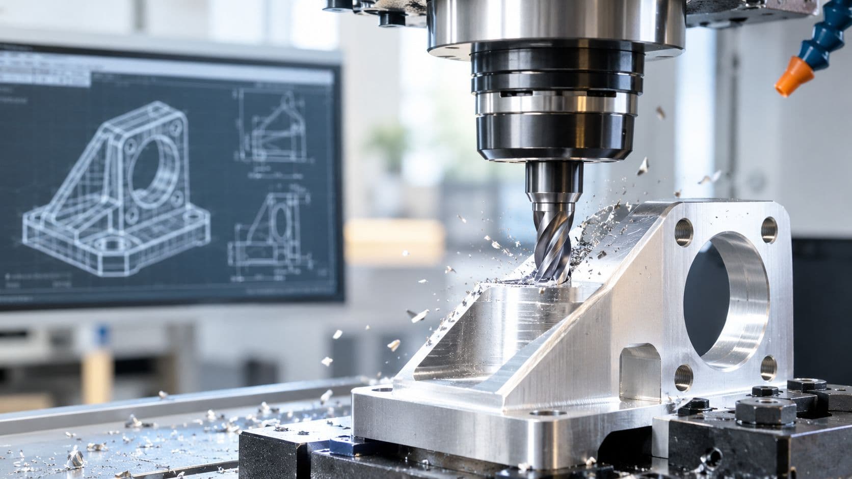
CNC remains a strong choice for prismatic parts, accessible pockets, precise interfaces, and materials that are already easy to machine. Casting can suit stable geometries and production volumes that justify tooling. Metal AM deserves review when geometric complexity, low volume, customization, weight reduction, or part consolidation reduce enough downstream work to offset printing and qualification costs.
A production decision, not a shape contest
Start the design review with the part's job:
- What must the part do? Define strength, fatigue, temperature, corrosion, wear, conductivity, and weight requirements separately.
- Which surfaces must be precise? Reserve machining stock for holes, sealing faces, bearing seats, and mating interfaces.
- What will inspection require? A printable internal passage may be difficult to clean, measure, or certify.
- What happens after printing? Support removal, stress relief, heat treatment, HIP, machining, polishing, and testing change the final cost and schedule.
- Would CNC or casting solve the same problem with less risk? Design freedom has value only when it lowers the total manufacturing burden.
Qualification effort can change the decision more than printer time. An aerospace flight part may need documented powder control, process records, heat treatment, nondestructive inspection, and repeated validation. A general manufacturing bracket may need fewer checks and tolerate a simpler finishing route. The same geometry can therefore make sense in one application and fail the business case in another.
Metal AM is moving from prototypes and tooling toward end-use production across aerospace, automotive, and general manufacturing. The opportunity depends on repeatable processing, documented material behavior, and a finishing plan defined before the first build. Industry coverage of metal AM commercialization points to that wider commercial shift, but market growth alone does not qualify a part. Each design still needs a route matched to its alloy, tolerances, post-processing, inspection, and validation burden.
How Metal 3D Printing Actually Works
A metal printer doesn't create a finished part in one continuous action. It builds many thin cross-sections, each bonded to the layer below. The closest everyday analogy is controlled welding performed on a very small scale. A heat source creates a molten pool, the pool solidifies, and the machine repeats the operation across the next slice of geometry.
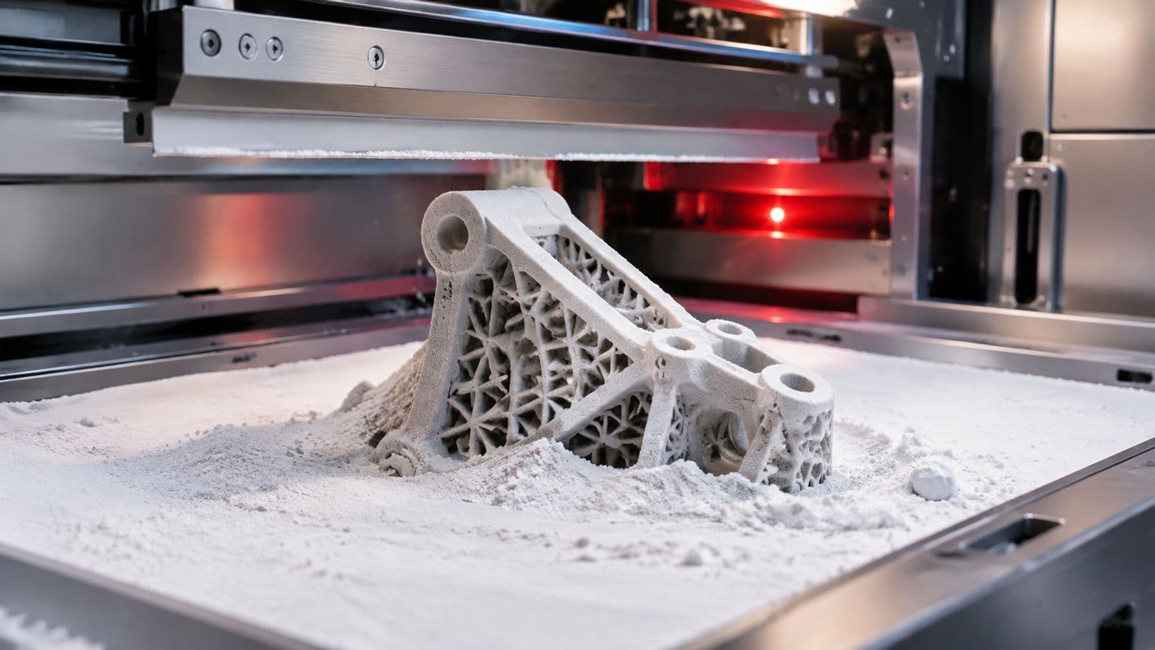
In laser powder bed fusion, a recoater spreads a thin layer of metal powder across a build plate. A laser follows the programmed scan paths and melts selected regions. The build plate then moves by the programmed layer increment, another powder layer is spread, and the cycle continues inside a controlled atmosphere.

The melt pool needs balance
The laser doesn't just need to deliver more energy. It needs to deliver the right energy for the powder, layer, and scan pattern. The main variables are laser power, scan speed, hatch spacing, and layer thickness. Together, they influence volumetric energy input and the behavior of the melt pool.
Too little effective energy can leave unmelted regions between scan tracks. This creates incomplete fusion and internal voids. Too much energy can destabilize the pool, produce keyholing, increase vaporization, and generate porosity. Reviews report that SLM parts typically show about 0% to 3% porosity, while optimized windows can produce relative density above 99.7% (review of LPBF process parameters and density).
Practical rule: Higher laser power isn't automatically better. The process must balance energy, movement, spacing, and layer geometry so the melt pool remains stable.
Different processes change the basic workflow
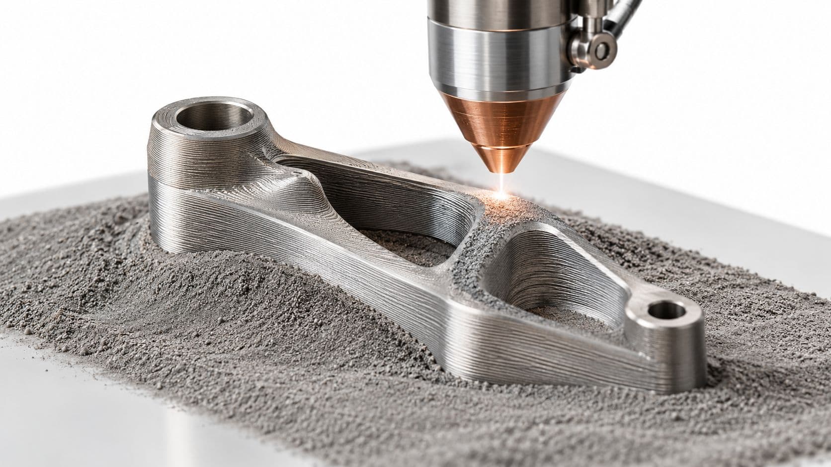
Powder bed fusion places powder across the entire build area and selectively melts or binds it. Directed energy deposition, by contrast, feeds powder or wire into a focused heat source as the deposition head moves. That makes DED useful for adding material to existing components, repairing high-value parts, or producing larger structures, although it generally needs substantial machining afterward.
Binder jetting deposits a liquid binder into a powder bed to create a fragile “green” part. The part is then removed from the loose powder and sintered so the metal particles bond. This separates shaping from melting, but introduces shrinkage control and sintering validation.
The process choice therefore starts with the part's job. Fine, intricate geometry may favor powder bed fusion. Large repair zones may favor DED. Higher-throughput production of suitable geometries may favor binder jetting. Each route changes the alloy options, surface condition, support strategy, dimensional control, and qualification plan.
Core Metal AM Technologies Compared
Engineers often ask which metal printing process is best. There isn't one answer because each technology optimizes a different combination of geometry, material, build scale, productivity, and finishing effort.
Laser powder bed fusion, also called LPBF, selective laser melting, or DMLS in some commercial contexts, is the general-purpose production route for intricate metal components. It creates fine features and complex internal passages, but it normally requires support structures, stress relief, support removal, and machining of critical surfaces.
Electron beam powder bed fusion uses an electron beam in a vacuum. It's particularly relevant to titanium and other high-temperature materials, and its thermal environment can reduce some stress-related challenges. The trade-off is a coarser surface and a process that may be less suitable when very fine details and smooth as-built surfaces dominate the requirement.
DED deposits powder or wire through a nozzle while a heat source melts the incoming material. Powder-fed DED can add material to a substrate, while wire-based systems can be attractive for larger structural builds. DED's strengths are deposition rate, repair access, and material efficiency in selected applications, but its surfaces and tolerances usually demand machining.
Binder jetting forms a part without melting the powder during the shaping stage. It can reduce support dependence and suit suitable batch production, but sintering creates dimensional change that the design and process must accommodate.
| Technology | How It Builds | Strengths | Limitations | Best For |
|---|---|---|---|---|
| LPBF, SLM, DMLS | Selectively melts powder with a laser | Fine detail, complex channels, broad industrial use | Supports, residual stress, rough as-built surfaces | Brackets, manifolds, tooling inserts, consolidated aerospace parts |
| EBM | Melts powder with an electron beam in vacuum | Useful for titanium and high-temperature alloys, warm build environment | Coarser surfaces, larger feature character, specialized equipment | Titanium structures, high-temperature materials, selected energy applications |
| DED | Melts powder or wire as it is deposited | Repairs, large structures, material addition, efficient buildup | Lower as-built resolution, significant machining | Repair, cladding, large near-net-shape components |
| Binder jetting | Binds powder, then sinters the shaped part | Reduced support needs, batch-oriented workflow | Shrinkage control, sintering development, powder handling | Suitable stainless parts and production geometries |
| Polymer SLS reference | Fuses polymer powder rather than metal | Useful for nonmetal prototypes and functional plastic parts | Not a metallic process | Plastic enclosures, fit checks, and early design validation |
For a broader contrast between additive and subtractive workflows, the SLS 3D printing overview helps place powder-based manufacturing in context. The selection decision should still come back to the part: alloy, envelope, tolerance, surface requirement, repair access, quantity, and qualification cost.
Recent industry commentary describes LPBF as the dominant production workhorse, DED as increasingly relevant to repair and large-scale applications, and EBM as strengthening in titanium, copper, high-temperature alloys, and energy-related materials (2026 industrial metal AM outlook). Those are not competing claims about one universal winner. They describe a division of labor.
Printable Metal Alloys and How to Choose Them
Alloy selection should begin with the part's dominant failure mode. A lightweight aerospace bracket has a different material problem from a hot gas component, a corrosion-resistant fluid fitting, or a wear-resistant medical component.
Stainless steels such as 316L and 17-4PH are common starting points. 316L offers corrosion resistance and ductility, while 17-4PH can be strengthened through precipitation hardening. They suit general engineering, fluid handling, tooling aids, and components that need a practical balance of printability and performance.
AlSi10Mg is a widely used aluminum option for laser powder bed fusion. Its low density and useful thermal behavior suit housings, lightweight brackets, and heat-management components. The design still needs careful attention to process parameters because porosity, surface condition, and heat treatment affect the final result.
Ti6Al4V is selected when strength-to-weight ratio, corrosion resistance, or biocompatibility matters. It's common in aerospace and medical applications, but residual stress and fatigue requirements make stress relief, orientation, finishing, and inspection especially important.

Heat changes the material decision
Nickel superalloys such as Inconel 625 and 718 serve high-temperature environments where ordinary aluminum or stainless steel would lose capability. They're relevant to turbine, combustion, chemical, and marine components, but they can require demanding scan strategies and heat treatment.
Cobalt-chrome suits wear-resistant and medical applications. Copper and CuCrZr are chosen for thermal or electrical conductivity, although copper can be more difficult to process because it reflects near-infrared laser energy and conducts heat away from the melt pool.
A useful selection sequence is:
- Rank the key property. Is it temperature, fatigue, weight, corrosion, wear, conductivity, or biocompatibility?
- Check process compatibility. Not every CNC-friendly alloy has an equally mature AM process window.
- Define the post-processing route. Stress relief, aging, HIP, machining, and polishing can change both properties and cost.
- Confirm inspection needs. A critical titanium part may need a more rigorous validation plan than a non-load-bearing stainless fixture.
- Use the least specialized alloy that meets the requirement. If 316L solves the job, choosing a difficult nickel alloy adds avoidable process burden.
The correct question isn't “Which metal is strongest?” It's “Which alloy delivers the required behavior after printing and finishing, through a process the supplier can control and document?”
Design for Additive Manufacturing Rules That Prevent Failure
A CAD model can be geometrically valid and still be a poor metal AM design. The printer follows the toolpath, not the engineer's intention. If a wall overheats, a cavity traps powder, or a support damages a sealing face, the machine won't reinterpret the design.
Start with orientation
Build orientation controls support contact, thermal history, surface condition, and the direction of repeated layers. A bracket placed flat may reduce build height but create broad downward-facing surfaces that need heavy support. Rotating it can reduce support contact and place critical holes in a more favorable direction, even if the build becomes taller.
That rotation also changes anisotropy and distortion risk. For a load-bearing part, orient the primary load path with the qualification data and finishing plan in mind. Don't choose orientation only by minimizing build time.
Make overhangs and supports deliberate
Unsupported downward-facing surfaces can sag or develop poor surface quality. Self-supporting slopes are generally easier to build than shallow overhangs, but the acceptable angle depends on the machine, alloy, layer settings, feature size, and thermal conditions.
Place supports where a technician can remove them without damaging a functional surface. Avoid burying support intersections inside inaccessible channels. If a support must touch a sealing face, bearing seat, or precision hole, add machining stock and ensure the feature can reach a cutter or finishing tool.
Design for powder and inspection access
A closed cavity may look elegant in CAD and become a powder-removal problem in production. Provide drainage paths where the process requires them, and ask how the supplier will verify the internal volume. CT inspection can reveal hidden conditions, but it adds cost and interpretation work. A channel that can't be cleaned, measured, or pressure-tested may not be production-ready.
Lattices and topology optimization can reduce mass and improve stiffness-to-weight performance, but they also complicate cleaning, finishing, and inspection. Use them where they serve a clear structural or thermal purpose, not solely because the process makes them possible.
Leave finishing stock
As-built surfaces rarely match machined surfaces. Add stock to interfaces that require tight size or smooth contact, then confirm that the selected machine and tool can reach those areas after heat treatment. The best AM designs separate surfaces that need precision from surfaces that can remain in the as-built state.

A printable shape is only the beginning. A manufacturable shape has a support plan, a powder-removal plan, a machining plan, and an inspection plan.
Post Processing Tolerances Surface Finish and Inspection
The printer stopping doesn't mean the part is ready. The build plate may still carry residual stress, supports may remain attached, and critical faces may need machining. For load-bearing parts, finishing is part of the engineering design, not a cosmetic afterthought.
A typical sequence can include:
- Stress relief: Reduces internal stresses before the part is removed from the plate or supports are cut away.
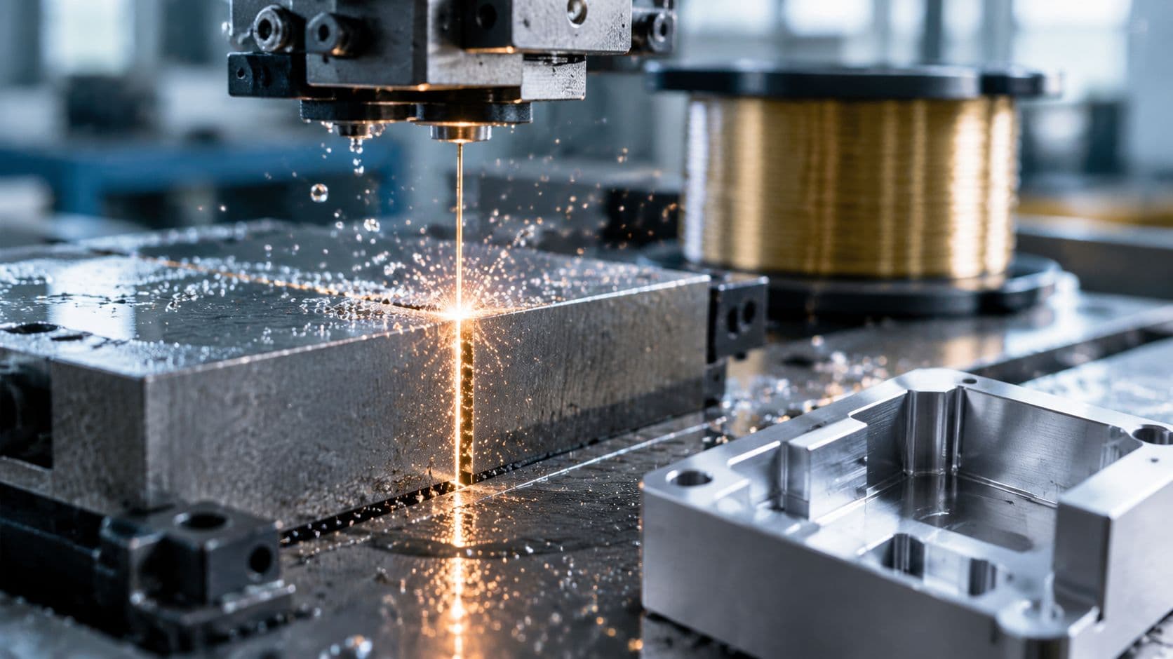
- Support removal: Uses cutting, grinding, wire EDM, or other methods selected around the geometry.
- Heat treatment: Adjusts strength, hardness, ductility, or microstructure for the selected alloy.
- HIP: Applies heat and pressure to address internal porosity in applications where fatigue and integrity demand it.
- CNC machining: Brings holes, datums, mating surfaces, and sealing interfaces to their specified dimensions.
- Polishing or blasting: Changes the surface condition where friction, cleaning, flow, or appearance requires it.
Surface condition has an outsized effect on fatigue. In a large review of Ti6Al4V fatigue behavior, rough as-built surfaces were identified as the most severe factor, reducing fatigue strength by up to 75% because asperities act as stress concentrators and crack-initiation sites (Ti6Al4V fatigue and post-processing review). The same review found that machining, polishing, and HIP can raise fatigue performance to levels comparable with conventionally manufactured material, with machining plus HIP particularly effective for electron-beam-printed parts.
Specify the finished condition
A drawing should distinguish between as-built and finished surfaces. Mark the faces that need machining, identify datums, define hole requirements, and state whether internal channels need pressure testing, visual access, or CT inspection. A single blanket surface requirement can make the part unnecessarily expensive because technicians may finish areas that have no functional role.
Inspection methods should match the risk:
| Requirement | Useful control | Why it matters |
|---|---|---|
| External dimensions | CMM, height gauge, micrometer, calipers | Confirms datums, fits, and envelope |
| Surface condition | Roughness measurement, visual inspection | Controls sealing, friction, cleaning, or appearance |
| Internal geometry | CT scanning, borescope, pressure test | Checks channels, trapped powder, and hidden defects |
| Surface-breaking flaws | Dye penetrant inspection | Finds defects that reach the surface |
| Material behavior | Tensile, hardness, fatigue, or other testing | Supports qualification and process validation |
| Internal density | CT or validated process controls | Evaluates porosity and consolidation |
For dimensional verification, CMM inspection services can be part of a broader route that connects the drawing, datums, and final report. The important point is to decide inspection before production, because a feature that cannot be accessed or measured may require a redesign.

Cost Lead Time and When to Choose Metal AM Over CNC
Metal AM is usually strongest when the part's value comes from geometry or customization rather than raw material removal. A consolidated assembly may eliminate fasteners and alignment work. A low-volume replacement may avoid dedicated tooling. A conformal channel may deliver a function that drilling can't create.
CNC is often the better choice when the part has accessible features, tight tolerances across many surfaces, predictable material behavior, and enough volume to justify efficient setups. Casting becomes attractive when the shape is stable and tooling cost can be spread across production. The comparison should include more than the machine cycle.
Count the hidden work
A realistic quote includes:
- Build preparation: Orientation, supports, nesting, and parameter selection.
- Material handling: Powder qualification, storage, recovery, and traceability.
- Post-processing: Stress relief, support removal, HIP, heat treatment, machining, and finishing.
- Inspection: Dimensional reports, internal inspection, material tests, and documentation.
- Qualification: Process consistency, repeat builds, acceptance criteria, and certification pathways.
Recent neutral coverage identifies qualification, process consistency, and certification as major industrial bottlenecks, rather than printing alone. It also notes that scaling remains constrained by technical and economic factors (review of industrial metal AM barriers.)
A practical workflow is to screen the design for AM opportunities, compare it against CNC and casting, select the alloy and process, design for support and finishing, then produce a pilot part with a defined inspection plan. If the part passes functional testing, repeatability and documentation become the focus. If the validation burden outweighs the geometric benefit, move the design back to CNC, casting, or a hybrid route.
FIRMFG offers DMLS and SLM metal printing alongside CNC machining, sheet metal, molding, casting, and finishing, with material options including titanium, aluminum, stainless steel, cobalt-chrome, and Inconel. Its stated quality systems include ISO 9001 and ISO 13485, and its manufacturing operation combines more than 300 machines with DFM support for prototyping and low-volume production. For a direct process comparison, the CNC versus 3D printing guide provides a useful starting point.
Share your CAD file, target alloy, critical tolerances, service conditions, and expected quantity with FIRMFG for a manufacturability review that compares metal AM with CNC, casting, and finishing requirements. The team can help define orientation, supports, post-processing, inspection, and a practical path from prototype to qualified low-volume production.