SLS 3D Printing: Process, Materials, and Real Costs
A hardware team has a nylon bracket that must survive drop testing, repeated snap-fit cycling, and real handling, but injection-molding tooling would lock up capital and delay the program. A cosmetic SLA model may look excellent, yet fail under impact. An FDM prototype may be available quickly, yet its layer direction can become the failure point.
That's where SLS 3D printing earns serious consideration. It produces functional polymer parts by fusing powder without dedicated support structures, which opens internal channels, undercuts, lattices, and nested assemblies that are awkward or impossible with other processes. The harder questions come after printability: how much powder control does the workflow require, how long will the build cool, and what will depowdering and finishing add to the quote?
Table of Contents
How the SLS Process Builds Parts Layer by Layer- The build sequence
SLS Materials, Tolerances, and Surface Finish- Choosing the powder
Design for SLS Rules That Save Time and Money- Start with walls and transitions
How SLS Compares to SLA, FDM, CNC, and Injection Molding- Ask the question behind the process choice
Real Costs, Lead Times, and Post-Processing Work- The hidden work in the quote
When SLS Is the Right Choice for Your Project- Strong signals for SLS
Working with a Manufacturing Partner on SLS Production- Give the supplier decisions, not just files
Why Engineers Are Choosing SLS for Functional Prototypes
A product team rarely needs a prototype that merely resembles the final part. It needs a bracket that carries load, a housing that survives assembly, or a snap-fit that can be cycled without crumbling. SLS fits that requirement because the laser fuses polymer powder throughout each layer, producing nylon parts with useful strength and ductility rather than prioritizing appearance alone.
SLS emerged from work at the University of Texas at Austin in the 1980s, where Carl Deckard and Joe Beaman developed and patented the process. The first machine, nicknamed Betsy, was completed in 1987, followed by Bambi in 1989, which introduced chamber preheating and a roller system that improved print quality and supported more complex shapes. DTM designed the first commercial SinterStation 2000 in 1992, and it was marketed in 1993, moving the process from laboratory invention toward industrial production. The University of Texas history of selective laser sintering documents that progression.
The design problem SLS solves
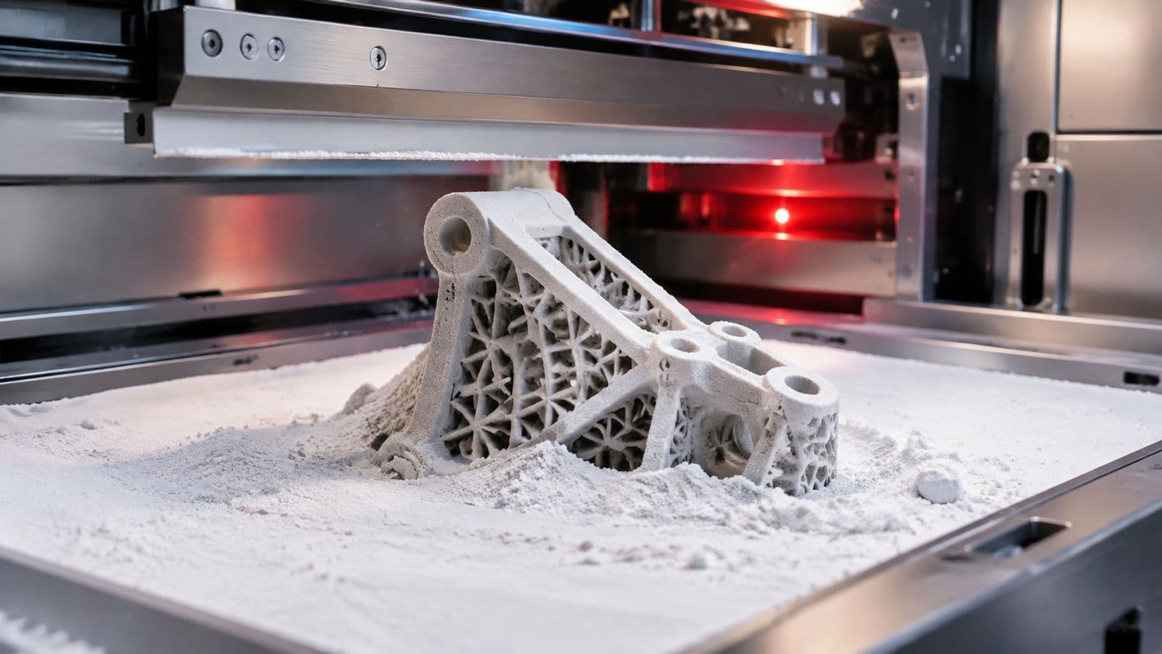
The practical advantage is freedom from sacrificial support scaffolding. Loose powder surrounds the part during the build, so engineers can create snap-fits, internal cavities, lattice structures, and complex ducts without designing removable supports into every overhang.
That makes SLS a useful middle ground:
- Against SLA, it generally favors impact resistance and functional nylon behavior, while SLA remains stronger for fine detail and cosmetic surfaces.
- Against FDM, it avoids the same dependence on visible filament paths and layer orientation, although FDM can still be sensible for quick, inexpensive concept checks.
- Against CNC machining, it handles enclosed geometry and intricate forms without requiring cutting-tool access from multiple directions.
- Against injection molding, it avoids tooling, making it practical while designs are still changing or volumes remain limited.
Buyer decision: Choose SLS when the part must behave like a functional polymer component, but the design or quantity doesn't yet justify tooling.
SLS has also become a substantial manufacturing market rather than a niche prototyping curiosity. One market estimate places the selective laser sintering market at $4.81 billion in 2025 and $5.73 billion in 2026, with a projection of $13.48 billion by 2031 at an 18.69% CAGR. A separate forecast estimates growth from $3.46 billion in 2025 to $9.08 billion by 2030, at a 21.3% CAGR. These estimates are summarized in the industry history and market document for SLS, and they point to a process increasingly used for production, not only prototypes.
How the SLS Process Builds Parts Layer by Layer
A product team can load several functional parts into one SLS build, then discover that the laser run is only part of the schedule. Powder preparation, controlled cooling, extraction, and cleaning all affect when usable parts reach assembly.
The build sequence
- The operator prepares the powder. Qualified polymer powder is loaded, its blend is verified, and storage and handling conditions are checked. The machine then establishes stable thermal conditions before exposure begins.
- A recoater spreads a layer. A blade or roller moves across the platform and deposits a uniform powder sheet. Layer thickness varies by machine and material, but each layer is thin relative to the finished geometry.
- The laser scans the slice. A high-power laser fuses only the powder assigned to that cross-section of the 3D model. Powder outside the scan remains loose and supports the surrounding geometry during the build.
- The platform lowers. After one slice is complete, the build platform drops by one layer thickness. The recoater covers the previous layer with fresh powder.
- The cycle repeats. Each scan bonds to the layer beneath it. Hundreds or thousands of layers can form the final part, depending on its height and the selected process settings.
- The powder cake cools. The chamber remains closed after laser exposure ends. Depending on build height and workflow, the powder cake may require 8 to 24 hours to cool before extraction, reducing the risk of warpage and crystallization defects. This cooldown is part of the production schedule, not idle time a buyer can assume away. The SLS production cost guide explains the process and cost factors that influence the schedule.

The surrounding powder supports overhangs and enclosed features throughout the build. Operators therefore avoid designing removable supports for every overhang, and parts can include nested components, internal channels, undercuts, and lattice fills with less support preparation.
That advantage shifts labor into powder handling and finishing. After cooling, operators excavate parts from the powder cake, brush or blast away loose material, recover usable powder, and inspect the surfaces. Powder storage, sieving, refresh ratios, and contamination control influence repeatability, so buyers should ask how a supplier governs powder between builds.
Buyer decision: Select SLS when support-free geometry matters, but include cooldown, powder recovery, cleaning, and inspection in the delivery plan. SLS reduces support work, it does not remove process work.
SLS Materials, Tolerances, and Surface Finish
Material selection determines whether an SLS part behaves like a rigid bracket, a ductile clip, a flexible seal, or a reinforced structural component. Commercial workflows commonly center on PA12, PA11, TPU, and filled nylon composites, but the values in a supplier datasheet should always take priority over generic material labels.
PA12 is the usual starting point for balanced stiffness, strength, chemical resistance, and dimensional behavior. PA11 is more ductile and is often a better candidate for snap-fits or parts exposed to impact. TPU serves flexible applications, while glass- or carbon-filled powders increase stiffness or strength at the cost of a less uniform response and more demanding finishing.
A peer-reviewed study of SLS PA11 reported 0.8% total porosity, an elastic modulus of 925 ± 52 MPa, and ultimate tensile strength of 45 ± 3 MPa. Those results, published in this PA11 SLS material study, show that SLS can produce near-dense functional nylon, while also confirming that process control matters.
Choosing the powder
| Material | Tensile Strength | Elongation at Break | Surface Finish as Printed | Best-Fit Applications |
|---|---|---|---|---|
| PA12 | Supplier-specific | Moderate ductility | Fine, grainy nylon texture | Brackets, housings, fixtures, general functional parts |
| PA11 | 45 ± 3 MPa in the cited study | Supplier-specific | Grainy, typically more ductile in use | Snap-fits, impact-prone housings, flexible functional prototypes |
| TPU | Supplier-specific | High flexibility | Textured and rubber-like | Seals, gaskets, grips, flexible covers |
| Glass- or carbon-filled nylon | Supplier-specific | Usually reduced versus unfilled nylon | Rougher, filled texture | Stiff brackets, lightweight structural parts, reinforced components |
The PA11 figures in the table come from the cited peer-reviewed study. For other materials, request the exact powder supplier's tensile and elongation data rather than treating a family name as a guaranteed specification. The nylon SLS material overview is a useful starting point for comparing available nylon options.
Tolerance and finish are separate decisions
SLS surfaces are typically grainy and lightly blasted in appearance. That texture hides the stair-stepping seen in some other additive processes, but it isn't equivalent to a polished injection-molded surface. Bead blasting, dyeing, vapor smoothing, coating, or machining can improve the result, but each option adds handling and inspection work.
Dimensional accuracy also depends on geometry, orientation, powder condition, and thermal behavior. Don't place a critical bearing seat, sealing face, or alignment datum on an as-printed surface without discussing inspection and possible secondary machining with the supplier.
Practical rule: If the part lives inside a housing, as-printed SLS may be entirely adequate. If a customer sees it, touches it, or evaluates it beside an injection-molded part, include finishing in the original design and quote.
Design for SLS Rules That Save Time and Money
SLS design freedom doesn't eliminate design-for-manufacturing discipline. It changes where that discipline belongs. Instead of designing support removal and mold release, the engineer focuses on thermal uniformity, powder evacuation, wall strength, and post-processing durability.
Start with walls and transitions
For PA12-style nylon parts, a wall around 0.8 to 1.0 mm can suit many nonstructural features, while load-bearing walls and bosses should generally be more substantial. These values are design guidance, not certification limits. A supplier should review thin sections that will be flexed, clamped, or handled aggressively during depowdering.
Uniform thickness matters because thick and thin regions cool differently. Large solid masses can retain heat longer than thin walls, increasing the risk of distortion or local stress. Use gradual transitions, generous internal radii, and hollowing or lattice structures where a solid block adds weight without improving the load path.
Build around powder removal
The surrounding powder supports the part, but it must eventually leave the part. Any enclosed cavity, internal channel, or hollow volume needs a deliberate powder escape strategy. Add accessible escape openings and place them where they won't compromise function or appearance. A sealed chamber that traps powder may be printable in theory but unusable after extraction.
Living hinges and snap-fits can work well in ductile nylon when the flex zone is designed intentionally. A thin hinge region around 0.4 to 0.6 mm may be appropriate for some concepts, but repeated cycling requires validation because hinge life depends on geometry, orientation, material condition, and stress concentration.

Use complexity where it pays
Lattices can reduce mass and powder consumption in thick sections, but they also create cleaning challenges. If an operator can't reach the interior, the geometry may retain loose powder and increase inspection time. Include access paths in the CAD model and confirm the supplier's depowdering method before committing to a dense internal structure.
Draft angles aren't required for SLS in the way they are for injection molding. They become relevant when the part will later interface with tooling or when a secondary molding operation requires release. A file that already prints cleanly in FDM will usually be accepted by SLS, but that doesn't mean it's optimized. Remove unnecessary supports, even out wall thickness, and check every cavity for powder escape before uploading.
How SLS Compares to SLA, FDM, CNC, and Injection Molding
The right process depends on what the part must prove. A cosmetic model, a load-bearing prototype, a machined datum, and a bridge-production component should not receive the same manufacturing recommendation.
| Process | Typical Tolerance | Surface Finish | Cost at 1 to 100 Units | Best Fit |
|---|---|---|---|---|
| SLS | Good for functional polymer geometry, supplier-specific | Grainy, bead-blasted, or finished | Moderate, with no tooling | Tough nylon prototypes, complex low-volume parts |
| SLA | Fine detail, supplier-specific | Smoothest among common polymer prints | Moderate | Cosmetic models, fine features, visual validation |
| FDM | Functional but strongly process- and orientation-dependent | Visible layer texture | Low to moderate | Fast concept checks, large simple parts |
| CNC | Tightest of these options when properly specified | Machined, with finishing options | Higher at low volume | Metal parts, precision datums, tight-tolerance components |
| Injection molding | Tool-controlled, supplier-specific | Mold-dependent | Tooling-heavy initially, economical at sustained volume | Repeated production with a stable design |
Ask the question behind the process choice
Choose SLA when surface detail, lettering, or visual presentation dominates and the part won't experience demanding impact. Choose CNC when a metal component needs tight dimensional control, reliable datums, or a machined surface. Choose FDM when speed and low cost matter more than finish and load direction.
SLS is strongest when the team needs functional nylon parts with complex geometry and a short path from design change to physical test. It avoids tooling while supporting forms that CNC may struggle to access. It also offers a more production-relevant material family than many appearance-focused prototype workflows.
Injection molding changes the economics once the design is stable and the volume is high enough to absorb tooling. The exact crossover depends on tool complexity, resin, part geometry, and order pattern, so don't use a universal unit threshold. For a broader process comparison, review this SLA versus SLS guide.
Decision shortcut: Cosmetic priority points toward SLA. Precision metalwork points toward CNC. Stable, repeated volume points toward molding. Functional nylon geometry under changing design conditions points toward SLS.
Real Costs, Lead Times, and Post-Processing Work
An SLS quote can look attractive until the team separates laser time from the work around it. Powder preparation, thermal control, extraction, cleaning, finishing, inspection, and process management all affect the delivered cost. Ask for that breakdown before comparing SLS with another process.
The hidden work in the quote
A completed build may require 8 to 24 hours of cooling before operators can extract parts safely. Build height and process conditions affect the duration. The machine has stopped lasing, but the job still occupies equipment and staff, and the parts are not ready for inspection. Opening the chamber too early can raise the risk of warpage and crystallization defects. A short laser cycle therefore does not guarantee a short shipment schedule.
After cooling, operators remove loose powder and recover usable material. The parts may then undergo bead blasting, dyeing, vapor smoothing, coating, or localized machining. Current estimates place post-processing at $5 to $15 per part, while one-off SLS parts can cost around $20 to $80, depending on the system and workflow. Use these figures as budgeting inputs, not as a substitute for a supplier quote. This rapid prototyping cost guide provides a broader framework for comparing prototype cost assumptions.
Build packing is another major cost lever. Because loose powder supports the geometry, a supplier can nest multiple components in one build. That may improve batch economics, but it does not eliminate powder refresh, operator time, inspection, or the need for consistent finishing across the lot.
Powder governance is a production cost
Powder handling should have its own line in a procurement review. Storage, sieving, refresh ratios, and contamination control influence repeatability and material cost. If a supplier cannot explain how powder lots and reuse are controlled, the quoted unit price may not describe a stable production process. See this SLS powder handling overview for the operating factors that affect reuse and handling.
Before approving a quote, ask what it includes:
- Cooling: Confirm that the lead time covers the full chamber cooldown.
- Depowdering: Check whether loose powder removal, brushing, and blasting are included.
- Finish: Specify as-sintered, dyed, vapor-smoothed, coated, or machined surfaces.
- Inspection: Identify measured dimensions and the report supplied with the parts.
- Material control: Ask how powder lots, refresh ratios, and reuse are tracked.
The practical schedule depends on packing, cooling, cleaning, finishing, and quality assurance, not only on laser exposure. Treat SLS as a complete production workflow.

When SLS Is the Right Choice for Your Project
SLS makes the most sense when three conditions meet: the part needs functional polymer performance, the geometry benefits from support-free fabrication, and the volume is too uncertain or too small to justify conventional tooling.
An annual requirement under 5,000 units can be a useful trigger to evaluate SLS, but it isn't an automatic recommendation. The correct decision depends on part size, packing efficiency, finish, inspection burden, and whether the design will remain stable. A small, simple part may still be cheaper with molding or machining, while a complex duct or custom enclosure may favor SLS even at a modest quantity.
Strong signals for SLS
- Mechanical testing is the priority. Nylon parts can support drop tests, assembly trials, and functional loading more credibly than many brittle appearance resins.
- The assembly needs snap-fits or flex zones. Ductile powder choices can reduce the need for screws and secondary hardware, provided the hinge or latch is validated.
- The geometry contains undercuts or internal features. The powder bed supports these areas without sacrificial scaffolding.
- The team needs parts in days rather than waiting for tooling. SLS supports design iteration while the mold strategy is still changing.
- The build contains multiple related components. Nesting can make a family of parts more practical than machining each component separately.
The failure modes are just as important. Very thin cosmetic walls can suffer from handling and finishing damage. Fine threads may need cleanup or machining. Optical clarity points away from nylon powder. High-volume production with a stable design may favor injection molding once tooling cost is spread across enough parts.
Use a simple decision rule
Ask whether the part must be tough, complex, and available before the design is stable. If the answer is yes, request an SLS quote. If the part must be glossy and presentation-ready, evaluate SLA or a finished molded process. If the part needs tight metal tolerances, start with CNC. If the quantity is high and repeatable, compare the fully loaded SLS cost with tooling and molded unit cost.

Working with a Manufacturing Partner on SLS Production
A successful SLS handoff starts before the quote. Send the native STEP file when possible, plus a watertight STL for printing, a drawing for critical dimensions, the required material, finish, quantity, and intended use. The supplier should check whether the mesh is manifold, whether wall thickness is suitable, and whether enclosed regions include escape paths for loose powder.
Give the supplier decisions, not just files
A useful request identifies the features that matter:
- Critical dimensions: Mark bearing seats, interfaces, sealing surfaces, mounting holes, and alignment datums.
- Functional loads: Explain whether the part sees impact, repeated flexing, compression, heat, chemicals, or assembly force.
- Finish requirements: State whether an as-sintered texture is acceptable or whether the part needs blasting, dyeing, vapor smoothing, coating, or machining.
- Quantity and timing: Provide the immediate batch size and expected repeat orders so the supplier can consider build packing.
- Powder requirements: Ask how the provider controls powder lots, refresh ratios, sieving, storage, and contamination.
A strong quote should identify more than material and unit price. Ask how the supplier plans orientation, how many parts fit in the build, what cooldown is included, and which post-processing steps are assumed. A low price that excludes depowdering or inspection isn't comparable with an all-in production quote.
Define quality evidence before the first build
For a production-intent part, request a dimensional report against the drawing. Critical features may require CMM or scan verification, while first articles can include tensile coupons or other process-validation samples. Powder-lot traceability matters when the same component must perform consistently across repeated builds or distributed production sites.
The schedule should include the actual workflow, not only print time. A realistic handoff may involve an overnight build, 8 to 24 hours of cooldown, depowdering, inspection, optional finishing, and shipment after the supplier releases the parts. Confirm the promised date in writing and ask which events would move it.
Before uploading, attach a concise file package:
- Watertight STL and native CAD.
- Dimensioned drawing with tolerances.
- Material and color specification.
- Finish callouts and masking requirements.
- Quantity, delivery date, and intended test conditions.
- Powder escape-hole notes for enclosed geometry.
- Inspection requirements for critical features.
FIRMFG provides SLS printing for functional prototypes and low-volume parts, with nylon options including PA12, PA12-GF, PA11, and TPU. The team also supports CNC machining, molding, casting, finishing, and inspection, which can help when the SLS design needs a machined datum or a later transition to another process.
FIRMFG can review your CAD, recommend an SLS material and finish, and quote functional nylon prototypes or low-volume production parts with the relevant inspection requirements. Visit FIRMFG with your STL, drawing, quantity, and target delivery date to start a practical process comparison.