Sheet Metal Gauge Chart: Thickness by Material

The usual advice is to find the gauge number and read across to the thickness. That skips the most important input: the material. A sheet metal gauge chart is useful only when you know which metal and gauge convention the supplier means.
For engineering work, gauge is a shorthand, not a complete thickness specification. Start with the material column, then turn the lookup result into an explicit thickness, tolerance, and purchasing requirement before releasing the part.
Table of Contents
Find the Gauge for a Measured Thickness- Work from the measurement to the row
How Material Choice Changes the Same Gauge- Treat substitution as a design change
How to Read a Gauge Callout Correctly- Turn the shorthand into an orderable requirement
Tolerances That Decide Whether Thickness Fits- Separate purchasing limits from functional limits
Galvanized and Coated Sheet Needs a Separate Callout- Define the base sheet and coating separately
Ductwork and Enclosure Charts Use Different Values- Duct compliance and enclosure stiffness are different decisions
Why Gauge Numbers Mean Different Thicknesses- Read the system behind the label
Gauge Thickness Chart for Steel, Stainless and Aluminum
Nominal gauge thickness by material
| Gauge | Carbon steel (in / mm) | 304 stainless (in / mm) | Aluminum (in / mm) |
|---|---|---|---|
| 14 | 0.0747 / 1.90 | 0.0781 / 1.98 | 0.0641 / 1.63 |
| 16 | 0.0598 / 1.52 | 0.0625 / 1.59 | 0.0508 / 1.29 |
| 18 | 0.0478 / 1.21 | 0.0500 / 1.27 | 0.0403 / 1.02 |
| 20 | 0.0359 / 0.91 | 0.0375 / 0.95 | 0.0320 / 0.81 |
| 22 | 0.0299 / 0.76 | 0.0312 / 0.79 | 0.0253 / 0.64 |
| 24 | 0.0239 / 0.61 | Confirm in the applicable material reference | Confirm in the applicable material reference |
The same gauge number is a different thickness in each metal, so always read the column for your material.
These are nominal thicknesses, not measurements of the sheet you'll receive. Carbon steel uses Manufacturers' Standard Gauge in this table. The stainless column is a thickness reference for stainless sheet, not a substitute for specifying the grade, finish, and applicable material requirements.
The unlisted cells deliberately require confirmation rather than an estimated value. Don't fill them by continuing a numerical pattern: gauge intervals aren't uniform, and interpolation can produce a thickness that isn't part of the intended series.
Use the chart for selection, not acceptance
Gauge numbers rise as sheet gets thinner. That makes the chart convenient for comparing nearby stock options, but the numerical difference between gauge labels doesn't describe a fixed thickness change.
For an early enclosure layout, use the chart to establish a candidate wall thickness and assess available space around bends, fasteners, and mating components. For a purchasing estimate, identify the material and nominal thickness before asking for pricing. A gauge number alone leaves the estimator to choose a convention you may not intend.
A production drawing needs more than a chart lookup:
- Material identity: Name the grade or alloy, not just steel or aluminum.
- Thickness requirement: State the nominal dimension and identify which unit system controls.
- Acceptance limits: Specify the permitted thickness range using the applicable material specification.
- Surface condition: Identify finishes or coatings that affect the finished interface.
Practical rule: A chart selects a candidate thickness. A drawing and purchase specification define an acceptable sheet.
Find the material column first, choose the nearest suitable stock option, and record the thickness in both units if the supply chain needs them. Make one unit system controlling and the other reference-only, so rounded conversions don't become competing acceptance limits.
Find the Gauge for a Measured Thickness
Reverse lookup starts with a measurement and a known material, not with a guess about the gauge. Use a micrometer on a clean, flat area away from burrs, cut edges, and local deformation. If the sheet is coated, establish whether you're measuring the base metal or the finished stack.
Work from the measurement to the row
- Normalize the units. Convert the measured thickness into the unit used by the chart. Preserve the original measurement rather than replacing it with a rounded gauge equivalent.
- Select only the column for the identified material. A nearby value in another column isn't a valid match.
- Compare the adjacent nominal thicknesses. Record the nearest listed row and the difference between that nominal value and your measurement.
- Check whether the measured value falls within the permitted range for the claimed material and thickness. Proximity alone doesn't establish compliance.
For a hypothetical sheet measured at 1.5 mm, the steel column points toward its listed 16-gauge option. In the aluminum column, the listed 14-gauge option is nearer than the listed 16-gauge option. That aluminum result means nearest among the displayed rows, not necessarily nearest among every gauge in a complete aluminum series.
Reverse lookup identifies a likely stock designation. It doesn't prove the material specification or authorize a substitution.
If you're selecting new stock between displayed rows, use weight and stiffness requirements to guide the decision, then validate the choice. If you're identifying received stock, don't choose whichever row makes the part acceptable. Keep the measured thickness on the inspection record and confirm the designation against the purchase order.
How Material Choice Changes the Same Gauge
Equal gauge numbers don't produce equivalent parts. The first visible failure may be an enclosure that won't close because someone converted the gauge using the wrong material column.
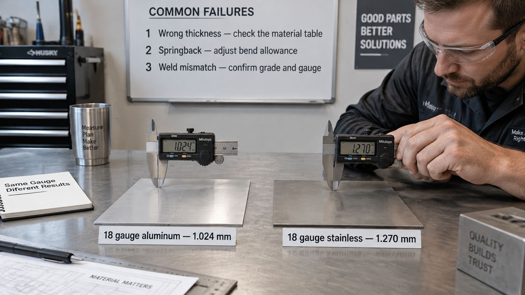
The PEKO Precision sheet-metal thickness reference lists 18-gauge aluminum at about 1.024 mm, compared with 1.270 mm for stainless steel, and 14-gauge aluminum at about 1.628 mm, compared with 1.984 mm for stainless steel. Those are changes to the physical section, not just alternative names for the same sheet.
Treat substitution as a design change
Stiffness comes first. Aluminum generally needs a different thickness or formed geometry to achieve comparable rigidity. Repeat the stiffness check using the replacement material and actual section, including flanges and unsupported spans.
Bending requires a fresh setup. The original bend deduction may no longer produce the intended flange length, and springback behavior changes with material and condition. Recalculate the flat pattern for the actual alloy and thickness, then verify a trial bend rather than transferring the previous setup unchanged. Material condition and finish also matter in stainless steel fabrication.
Thread engagement deserves a separate check. A hole may remain correctly positioned while the thinner sheet provides insufficient engagement for the fastening method. Measure the sheet before tapping, and consider an insert, captive fastener, or revised section when direct threading isn't suitable.
Gauge symptoms, causes and fixes
| Symptom | Likely cause | Fix |
|---|---|---|
| Part does not fit the enclosure | Gauge converted using the wrong material column | Re-specify in mm with grade and standard, then check fit |
| Bends come out short or tight | Bend allowance taken from another metal | Recalculate bend deduction for the actual alloy and thickness |
| Holes or threads will not engage | Sheet thinner than the engagement assumed | Measure the sheet with a micrometer; add engagement or use thicker sheet |
| Weld gaps at fit-up | Tolerance on heavier sheet ignored | Add the tolerance to the drawing and verify the received sheet |
| Low stiffness after substitution | Aluminum swapped for steel by gauge number | Repeat the stiffness check using the new material |
| Mass estimate is off | Coating or plating allowance ignored | Include the coating allowance in the mass calculation |
Finally, rebuild the mass and cost estimate from the replacement material, actual thickness, and finish. Don't assume a lighter base metal makes the finished design cheaper if it requires additional forming, hardware, or reinforcement.
Choose the alloy first, then the thickness, and use gauge only as a label. That sequence keeps material substitution from changing the geometry.
How to Read a Gauge Callout Correctly
A usable callout must tell purchasing what to order and inspection what to accept. The National Bureau of Standards circular on standard gauges documents gauge systems as defined references, rather than a universal material-independent thickness scale.
Use the following release procedure when a customer drawing, legacy print, or supplier quotation gives only a gauge.
Turn the shorthand into an orderable requirement
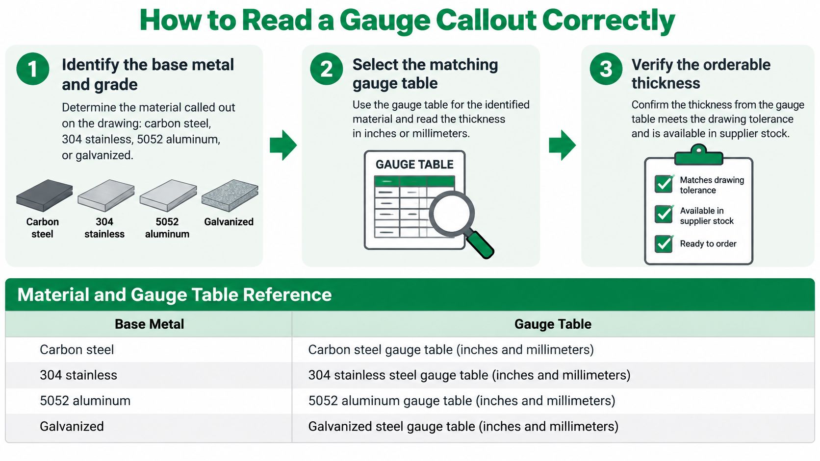
- Identify the base metal and grade. Establish whether the requirement is carbon steel, stainless, aluminum, or coated steel. Skipping this decision creates ambiguity before anyone reaches the thickness column. For aluminum, include temper; for stainless, identify the required grade and finish.
- Read the matching material-specific gauge table. Record which convention you used so a second person can reproduce the lookup. The common slip is treating a familiar shop chart as applicable to every sheet product.
- Confirm the governing specification and edition. Check that it applies to the product form, material condition, and order. A general requirements specification may need an accompanying grade or product specification; naming a standard doesn't automatically complete the material description.
- Write the nominal thickness explicitly in millimeters and inches where both are useful. Designate the controlling units and retain gauge only as a reference. This prevents purchasing and fabrication staff from independently translating the same label into different dimensions.
- Add the permitted minimum and maximum thickness. Obtain the correct limits from the applicable specification or an agreed purchase requirement. Don't copy a tolerance from another alloy, width, or rolling condition because its nominal thickness looks similar.
- For formed parts, define the inside bend radius, flange geometry, and relevant coating or plating allowance. A correct sheet thickness doesn't guarantee a correct formed envelope if the flat pattern or surface stack is wrong.
- Require verification before release. Compare received material with the purchase specification and supporting mill certificate or inspection record. A supplier's gauge description isn't a substitute for the required material identity and dimensional acceptance.
Make inspection requirements executable
Tell the inspector which dimensions control assembly and where thickness must be checked. Keep raw-sheet acceptance separate from finished-part inspection, especially when forming or finishing changes the accessible measurement surfaces.
At FIRMFG, we perform dimensional inspection using CMM and calibrated digital calipers, with results documented against CAD nominal values and specified tolerances. We also provide free DFM feedback for CNC machining; that review doesn't replace the material and thickness requirements needed for a sheet-metal order.
Governing specifications by material
| Material | Governing specification | What to call out on the drawing |
|---|---|---|
| Carbon steel sheet | ASTM A568/A568M, with the applicable product specification | Grade, nominal thickness in mm and in, tolerance |
| Stainless steel sheet | ASTM A480/A480M, with the applicable product specification | Grade such as 304 or 316, nominal thickness, finish, tolerance |
| Aluminum sheet | ASTM B209/B209M | Alloy and temper, nominal thickness, tolerance |
| Galvanized steel sheet | Applicable coated-sheet specification identified on the purchase order and mill certificate | Coating designation with base thickness and tolerance |
Send the drawing with the selected material reference, controlling thickness, and permitted thickness range. That gives the supplier a defined requirement rather than a conversion exercise.
Tolerances That Decide Whether Thickness Fits
A published sheet-metal gauge and tolerance summary reports ASTM A568 variation from roughly ±0.002 in for thin cold-rolled gauges to ±0.008 in or more for heavier hot-rolled material. It also gives representative examples of ±0.005 in for 16-gauge cold-rolled steel, ±0.004 in for 18-gauge steel, and corresponding 5052 aluminum examples of ±0.004 and ±0.003 in.
Those are reference examples, not universal purchasing limits. The applicable tolerance depends on the product specification, thickness, width, and material condition. A nominal 1.5 mm sheet therefore isn't necessarily a measured 1.500 mm sheet.
Separate purchasing limits from functional limits
A sheet can comply with its material specification and still fail an assembly requirement. That happens when the designer allocates all available clearance to nominal geometry and leaves no room for permitted thickness variation.
Distinguish the following requirements:
- Nominal designation: The intended stock thickness and supplementary gauge label.
- Material acceptance range: The minimum and maximum thickness permitted by the order.
- Functional restriction: A tighter requirement where a particular interface cannot accommodate the normal stock range.
Don't tighten the entire sheet specification because a local feature is sensitive. First check whether a revised fastener, relieved interface, or different formed geometry can accommodate standard stock.
Check the features that amplify variation
Bend deduction and press-brake setup respond to actual thickness, so validate the flat pattern and tooling assumptions before committing to a batch. For sheet metal bending, distinguish a material-thickness problem from a tooling or bend-sequence problem before adjusting the program.
Mating clearances and thread engagement need a worst-case check rather than a nominal-only check. Weld fit-up requires the same discipline: compliant parts at opposite ends of their permitted ranges may create a joint condition that the fixture doesn't accommodate.
Inspection priority: Verify the thickness that controls the fit, not merely the gauge written on the packing label.
For prototypes, an available stock substitution can support early shape validation, but it shouldn't silently become the production baseline. Measure incoming sheet with a micrometer and compare the results with the mill certificate and purchase limits before final assembly, particularly for calibrated mechanisms.
Galvanized and Coated Sheet Needs a Separate Callout
Galvanized sheet is deliberately absent from the opening conversion table. Don't estimate its orderable thickness from the uncoated carbon-steel column. Use the applicable coated-sheet specification identified on the purchase order and mill certificate.
A supplier's quoted thickness may describe the base steel or the coated product. Those aren't interchangeable descriptions when the assembly depends on the finished surface. Resolve that distinction before approving the quotation.
Define the base sheet and coating separately
Write the callout in a sequence that purchasing can follow:
- Base metal and grade. Establish the structural material before describing the surface treatment.
- Base thickness. State the controlling thickness and reference conversion, clearly identifying it as base-metal thickness.
- Coating designation. Name the required coating rather than relying on a generic description such as coated steel.
- Base-sheet tolerance. Identify the accepted range and separately define any finished-envelope restriction.
The distinction matters at bends and contact surfaces. Don't use an overall coated measurement as proof of base-metal compliance unless the governing acceptance method explicitly allows it.
Check joints and weight independently
At welded joints, coating is part of the joint-preparation decision, not an extra dimension to ignore. Confirm the intended fit-up condition, coating treatment, and welding procedure together. A nominal gap taken from an uncoated design may not describe the surfaces the welder receives.
For mass estimates, calculate the base sheet and coating contributions separately. Keep any subsequent plating, paint, or powder coating in the finished-part estimate rather than treating the base-metal calculation as the completed assembly weight.
The immediate check is simple: ask the material supplier whether the quoted thickness is base or coated, then record the answer in the purchase requirement and drawing notes. That written distinction is more useful than adding another gauge label.
Ductwork and Enclosure Charts Use Different Values
Ductwork references must be selected for the application, not copied from a general steel table. The Engineering ToolBox SMACNA ductwork reference lists the following nominal thicknesses for its ductwork gauge table.
SMACNA ductwork gauge values
| Gauge | Thickness (in) | Thickness (mm) |
|---|---|---|
| 16 | 0.0625 | 1.588 |
| 18 | 0.0500 | 1.270 |
| 20 | 0.0375 | 0.953 |
| 22 | 0.0312 | 0.793 |
| 23 | 0.0280 | 0.711 |
These values aren't interchangeable with carbon-steel Manufacturers' Standard Gauge values. Beyond that, duct construction isn't specified by thickness alone: material type, reinforcement, seam design, panel size, and pressure class all affect the construction requirement.
Duct compliance and enclosure stiffness are different decisions
For ductwork, establish the applicable construction requirements before selecting the sheet. A general-purpose gauge conversion doesn't establish that a panel and seam arrangement are appropriate for the service.
For an enclosure or bracket, assess the geometry and loading directly. Unsupported span, inside bend radius, flange width, fastening method, vibration, and handling loads determine whether the candidate thickness makes sense. A material that cuts economically may still need a more effective section to control deflection.
Useful reinforcement choices include:
- Hemmed edges: Stiffen exposed edges while changing their finished geometry.
- Return flanges: Add section depth around broad panels.
- Ribs and formed beads: Control local panel movement and oil-canning.
- Spot-welded features: Join reinforcing elements where the design and material permit.
Treat each feature as a geometry change that also needs clearance and manufacturing checks. The practical question isn't whether thinner sheet is strong enough, but whether the complete formed design meets its stiffness and assembly requirements.
Release the complete construction definition
Before production, document nominal thickness, material condition, coating or plating allowance, inside bend radius, and tolerance basis. Use sheet metal enclosure design considerations to check interfaces and panel geometry alongside the thickness decision.
The chart supports initial selection; final acceptance follows the applicable material and fabrication requirements. Complete the material callout using the governing-specification table, then add the application-specific construction details.
Why Gauge Numbers Mean Different Thicknesses
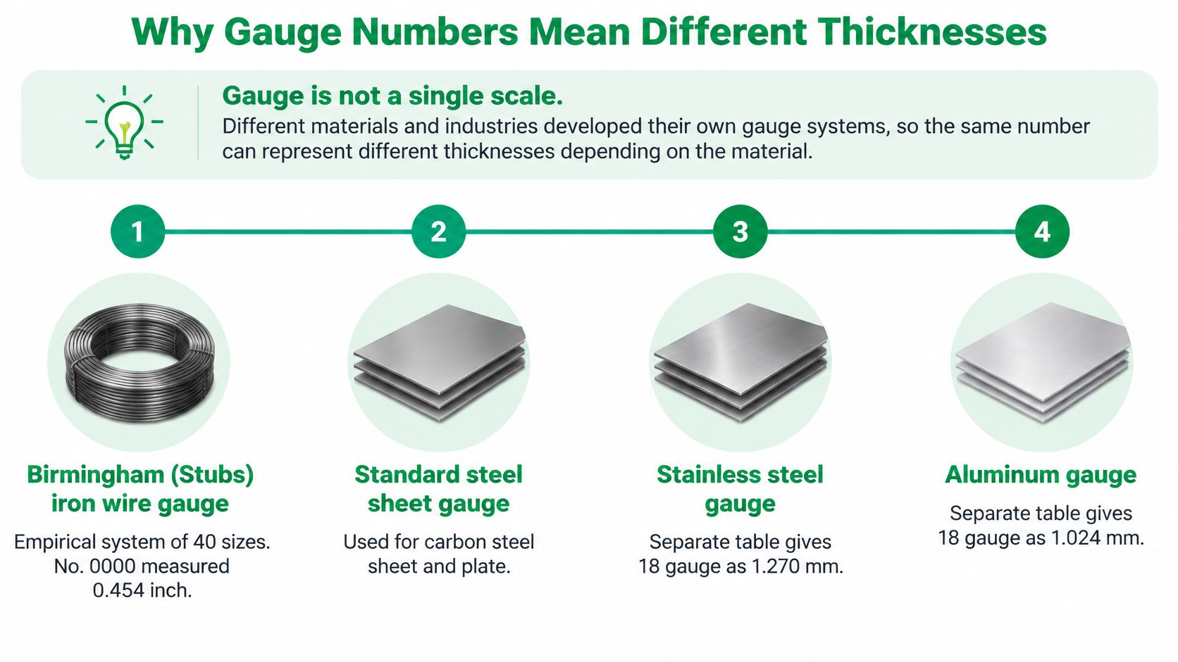
A legacy drawing can say steel gauge without identifying which historical system its author intended. That ambiguity exists because gauge developed through competing conventions, not a single mathematical scale.
The U.S. Bureau of Standards publication on gauges describes Birmingham, also called Stubs' iron wire gauge, as an empirical system with 40 sizes, from No. 0000 at 0.454 in to No. 36 at 0.004 in. It also records the decimal-gauge recommendation in 1877, congressional establishment of the mass-based U.S. Standard Gauge in 1893, and renewed advocacy for decimal gauge in 1895.
Read the system behind the label
The historical attempts at standardization didn't make every existing gauge designation interchangeable. Some references described empirical wire sizes; others expressed decimal thickness or used mass as the basis for sheet measurement.
Gauge systems and where they still apply
| System | Basis | Where it still appears | Example value |
|---|---|---|---|
| Birmingham (Stubs) iron wire gauge | Empirical wire sizes | Wire and tubing references | No. 36 = 0.004 in |
| Standard Decimal Gauge | Thickness in thousandths of an inch | Decimal thickness references | Read directly in thousandths |
| U.S. Standard Gauge | Mass per area, established for taxes and duties | Historical references | 16 = 1/16 in (0.0625 in) |
| Manufacturers' Standard Gauge | Thickness for uncoated carbon-steel sheet | Carbon-steel sheet in U.S. practice | 16 = 0.0598 in |
| Brown & Sharpe / AWG | Gauge convention used for aluminum and nonferrous sheet | Aluminum-sheet references | 16 = 0.0508 in |
The Steel Market Update history of Manufacturers' Gauge illustrates the consequence: historical U.S. Standard Gauge 16 was 0.0625 in, while Manufacturers' Standard Gauge 16 is approximately 0.0598 in, a difference of 0.0027 in, or about 4.3% relative to the historical value.
A replacement part can therefore follow the original gauge label and still differ from the intended section. When translating an older drawing, establish the material, named gauge system, and functional dimensions before selecting current stock. A modern chart is a conversion reference, not a ruler.
We offer sheet metal fabrication in aluminum, brass, and stainless steel with no minimums, including cutting, bending, and surface treatment. Visit FIRMFG with your drawing, material grade, nominal thickness, and permitted tolerance to discuss a prototype or short-run build without leaving the gauge conversion open to interpretation.