Sheet Metal Enclosure Design: A Step-by-Step Guide
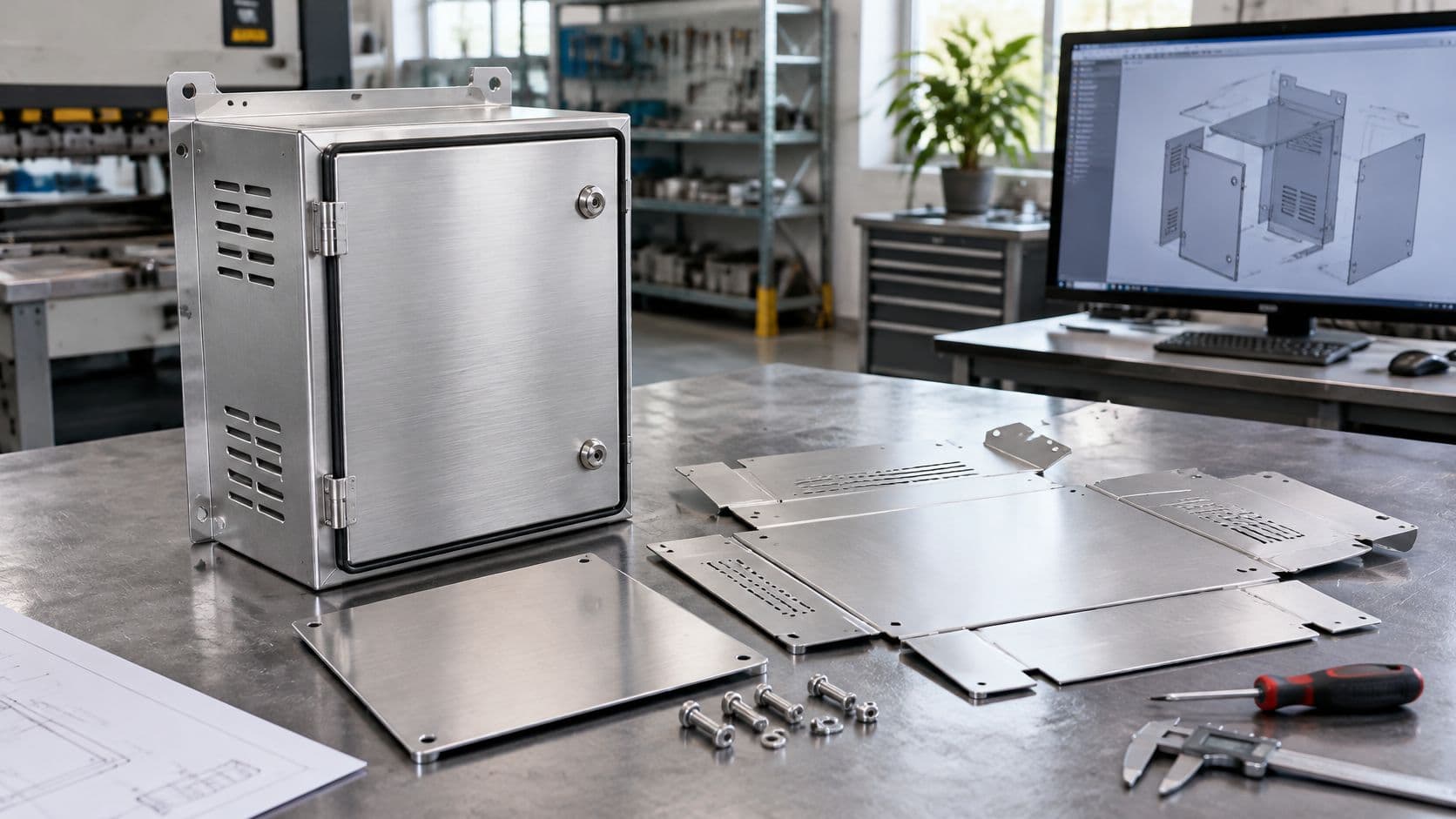
The first enclosure quote comes back with three redlines and a note you didn't plan for. The 6061-T6 flange will crack at the outside radius, the gasket you drew needs a deeper groove, and the vent slots sit close enough to a bend that they'll pull oval once the press brake touches them. None of it is a design error in isolation. It's an ordering problem.
IP rating, heat load, grounding and physical security get treated as four separate sign-offs. They're one decision, and it has to be made before anyone draws a bend radius or places a hole. A flange sized for 20 to 30 percent gasket compression is a different flange from the one sized for a butt seam. A vent sized for airflow is a different vent from the one sized to stop a probe. Settle the coupled decision first and the layout follows. Skip it and every revision is a negotiation with physics.
Table of Contents
- Material, Thickness and Bend Values to Design With
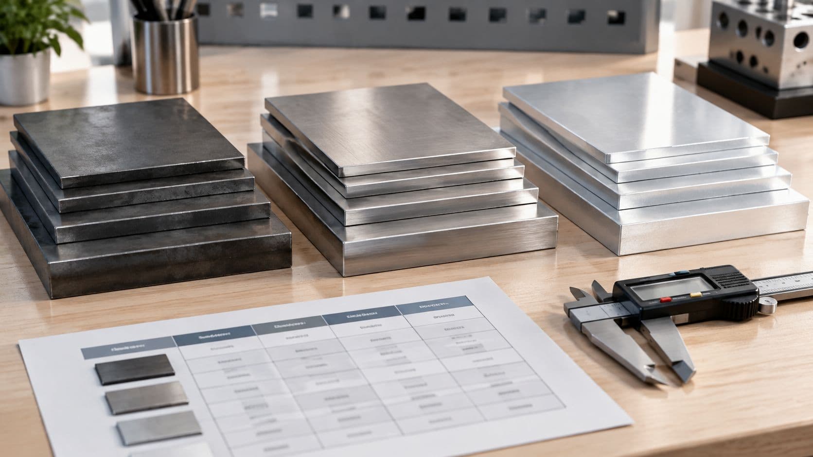
Bend radius and K-factor reference by material
What each material costs you in the press brake
Matching IP Rating, Gaskets and Cooling
When Tamper Resistance Is Worth the Cost
How to Lay Out Flanges, Seams and Corners
Hole, Vent and Fastener Placement Rules- Fasteners for thin panels
DFM Limits for Laser, Bending and Stamping- What each limit does to your drawing
Confirm the Design and Order a First Prototype
Material, Thickness and Bend Values to Design With
The cracked flange is the most common first-prototype failure in enclosure work. A designer draws a clean 90-degree bend in 6061-T6, the shop forms it, and the outside of the radius splits open. T6 temper has most of its ductility heat-treated away, so a tight bend has nowhere to go. Shop skill doesn't rescue that. The alloy and temper have to be picked against the bend needed, before the flat pattern exists.
Ingress protection governs most of these choices. The IEC 60529 IP classification covers electrical equipment up to 72.5 kV and splits protection into a solid numeral from 0 to 6 and a liquid numeral from 0 to 9, and the same guide notes that metal enclosures typically use sheet between 0.75 mm and 2 mm thick, folded and welded for rigidity.
The rating is achieved by the assembly, not by the shell. Door and lid geometry, gasket compression, fastener spacing, hinge behaviour, seams, ventilation features and cable entry all move the number. That's why the IP target belongs in the concept review, not in the inspection report at the end.
Thickness is the other value to fix first, because it sets the minimum inside bend radius, the flange length, the bend allowance and every hole clearance. Change it later and all of those change with it.
Bend radius and K-factor reference by material
| Material | Typical thickness | Min inside bend radius | Design note |
|---|---|---|---|
| 6061-T6 aluminum | 1-3 mm | 3-4T | Cracks on tight bends, use a larger radius |
| Cold-rolled steel (CRS) | 0.75-2 mm | 1T | Cost-effective for painted enclosures |
| 304 stainless steel | 0.75-2 mm | 1.5-2T | Higher springback, allow extra overbend |
| Galvanized steel (G90) | 0.75-2 mm | 1.5T | Zinc coating flakes on tight bends |
K-factor locates the neutral axis inside the bend as a fraction of thickness. Air bending runs roughly 0.33 to 0.45 depending on material and the radius-to-thickness ratio, so a radius near one thickness in 5052 sits close to 0.35 while a wide radius in soft steel pushes toward 0.45. Get it wrong and the blank comes out short or long by a millimetre or two per bend, which is enough to close up a door gap.
What each material costs you in the press brake
5052-H32 aluminum is the friendliest of the group. It takes a 1T inside radius without complaint, welds cleanly and holds a gasket groove. If your enclosure is aluminum and nothing forces you to 6061, start here.
6061-T6 buys you stiffness and machinability and charges you 3T to 4T in bend radius. Use it when the part is a machined block with a flange on the side, not when the part is a box.
304 stainless springs back hard. You'll overbend two to three degrees to land a 90, and the material work-hardens as it forms, so a second hit on the same corner behaves differently from the first. It's the right call for washdown and chemical exposure, and the wrong call for a cheap indoor cover. G90 galvanized wins on cost for outdoor painted boxes, but the zinc coating crazes on tight bends and flakes at a sharp radius, so keep 1.5T minimum and plan a zinc-rich touch-up on cut edges and bend lines.
Lock material and thickness in the drawing title block before a single flange dimension is drafted. Every other number in this article derives from those two.
Matching IP Rating, Gaskets and Cooling
A sealed enclosure can meet its IP target and still overheat. Decide the required ingress protection, cooling method, EMC path and level of access resistance together, before locating seams, vents or fasteners. Each opening or joint affects more than one requirement.
Read the two-digit IP target in physical terms before drawing the enclosure. IP54 means dust-protected and splash-resistant. IP65 means dust-tight and protected against water jets. IP67 means dust-tight and protected against temporary immersion. The target affects gasket compression, seam design and cooling options, so choose it for the installed environment rather than copying a competitor's specification.
| IP target | Protection meaning | Gasket and seam | Cooling and vent trade-off |
|---|---|---|---|
| IP54 | Dust-protected and splash-resistant | Closed-cell EPDM or silicone, compressed about 20–30 percent | Filtered vent or fan; dust can enter through the airflow path |
| IP65 | Dust-tight, protected against water jets | Compressed gasket; continuous welded or bonded seams | Filtered fan or heat exchanger; vents need baffling or filtration |
| IP67 | Dust-tight, protected against temporary immersion | Compressed gasket and sealed cable glands; no unfiltered openings | Heat exchanger or external fins; no open vent |
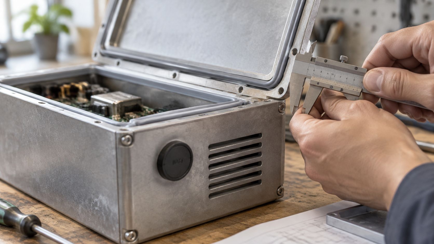
Gasket fit depends on compression and how evenly the door applies it. Seat closed-cell EPDM or silicone sponge in a groove so the door compresses the gasket 20 to 30 percent of its free height. Check compression around the full perimeter. A side-hinged door with latches opposite can squeeze the gasket hard near the latches and leave it loose near the hinge. Add latches or stiffen the door to even out compression; a thicker gasket does not fix uneven loading.
Cooling determines where openings can go. Add the heat loads from power supplies, drives and radios, then assess whether the enclosure's surface area can dissipate that heat. A filtered fan moves substantial heat at low cost, but admits dust and needs filter maintenance. A heat exchanger costs more and keeps the enclosure closed. A larger, unvented box may avoid both compromises.
The trade-off: every vent creates potential paths for dust, water and probing. Baffles and filters can limit exposure, but they also restrict airflow, so account for that when selecting the cooling method.
EMC design belongs in the same decision. Bonded seams, conductive gaskets and a grounding braid across a hinged door provide paths for electrical bonding. Keep grounding contact areas bare, because powder coat insulates the joint. Grounding and shielding choices should suit the equipment and installation; do not treat them as a substitute for controlling openings or sealing the enclosure.
Validate the three requirements separately: test ingress protection against the target, measure temperature rise at worst-case load in the intended ambient, then run a pre-compliance EMC scan. Passing one test does not establish that the enclosure will pass the others.
When Tamper Resistance Is Worth the Cost
Picture a controller in an unmanned roadside cabinet. The reset button sits on the outside face because service techs asked for it. The cable gland enters through the door because that was the easy route. Anyone with a screwdriver has line-of-sight to the board, ten minutes alone, and a button that reloads firmware.
Thicker sheet metal is a weak answer to that. Attackers don't cut through a 2 mm panel. They remove covers, loosen glands, unscrew hinges and press exposed buttons.
The NIST requirements for cryptographic modules are a useful ladder because they separate basic physical protection from levels that demand tamper-evident mechanisms, tamper detection and resistance to probing through ventilation openings. Those physical security requirements also note that ventilation openings or slits may need a bend or obstruction inside to prevent undetected access. That's the design-level version of the question you're asking.
Low risk, indoor, supervised. Replace exposed screws with captive fasteners so covers can't be left loose, and fit a door-open switch wired to the event log. Cheap, and it catches the honest mistake as well as the dishonest one.
Medium risk, unattended, serviceable. Add serialised tamper seals on covers, security screws on the door and protected cable routing so a gland can't be backed out and re-entered unnoticed. Seals cost pennies and give you a timestamp.
High risk, public location, valuable assets. Add intrusion detection, labyrinth or baffled vents that kill line-of-sight probing, and locks rated to the same level as the door skin. A high-security lock in a 1 mm door is decoration.
Three questions settle it before you add any hardware. What does the box protect (credentials, firmware, safety settings, measurements)? Who can physically reach it, and for how long? How often will a technician legitimately open it?
Every feature you add is a part, a bend or a process step. Price it at the design stage, while the flat pattern is still soft, not after the first prototype comes back.
How to Lay Out Flanges, Seams and Corners
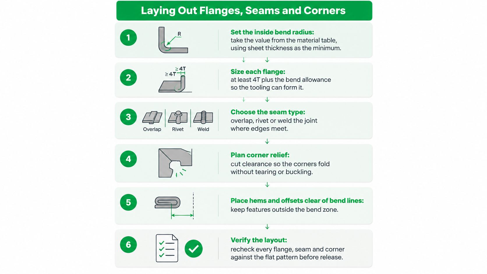
The flat pattern is where the coupled decisions become geometry. Work through it in this order and the blank will form without a second revision.
- Set the inside bend radius from the material table. Use sheet thickness as the floor for soft tempers and go to 3T or 4T for 6061-T6. Choosing the radius after the flange height is backwards, because the radius constrains the flange.
- Make every flange at least 4T plus the bend radius. Below that, the press brake punch has nothing to grip and the flange rolls or slips. This single rule kills more layouts than any other, because a 1.5 mm panel needs roughly 7 mm of flange before the bend even starts.
- Cut bend relief at every corner where two flanges meet. Size it about 1.5T wide and deeper than the bend radius plus T. Without relief, the material has to stretch at the intersection and it either tears or bulges, and both show up after paint.
- Choose the seam by how the part gets joined. Tab-and-slot for welded joints, overlapping flanges for rivets or fasteners, and hems for stiff exposed edges that must not cut a hand. Pick the seam before the corner detail, since the seam sets how much material the corner needs.
- Calculate the flat length with bend allowance, using BA = angle × π/180 × (R + K × T). A 90-degree bend in 1.5 mm 5052 at R 1.5 mm and K 0.35 gives 1.5708 × (1.5 + 0.525), which is 3.18 mm per bend. Five bends and the blank is 16 mm shorter than the folded part's outside dimensions, which is exactly the error that makes a door not fit its frame.
- Bend one scrap panel and measure it before releasing the drawing. Check flange angles, overall dimensions and hole positions against the model.
Bend sequence matters as much as bend geometry. Check that the punch and die can reach every flange in the order the shop will form them, and that no earlier bend blocks access to a later one. That's the constraint that usually forces a design change, and it's the one precision bending shops flag in review rather than on the floor.
A good first article looks like this: flange angles within about 1 degree of nominal, no cracks or orange-peel on the outside radius, corners that close without a visible gap, and a door that swings without needing force to latch.
Hole, Vent and Fastener Placement Rules
Holes move when the metal flows. A round hole placed 1 mm from a bend line becomes an oval after forming, and a slot that crossed a bend line becomes a tear. That's why every feature gets measured from the bend line, not from the flange edge, and why the flat pattern needs its clearances checked before cutting.
| Feature | Minimum rule | Why it matters |
|---|---|---|
| Hole to bend line | At least 3T plus the bend radius | Holes distort or oval when the metal flows in the bend |
| Round hole diameter | At least 1T | Smaller punches and drills break or wander |
| Slot width | At least 1.5T | Narrow slots tear or deform during forming |
| Hole to panel edge | At least 2T | Keeps the edge from tearing under fastener load |
| Hole to hole spacing | At least 2T | Prevents the web between holes from collapsing |
| Self-clinching fastener to edge | At least 2T, set by the stud datasheet | The supporting web needs enough material to hold the stud |
Fasteners for thin panels
A thread-forming screw needs a pilot hole sized to the screw's minor diameter, and it needs sheet thick enough to engage three full turns. On a 1 mm panel that's rarely possible, so a self-clinching stud or nut goes in instead, pressed before finishing. For a service door that opens weekly, use a captive fastener, since loose hardware inside an enclosure is a short-circuit waiting to happen.
Vent louvers and slot arrays belong on flat, unformed areas of a panel, kept clear of bend lines and away from the gasket land. A louver cut into a bend relief area destroys both functions. Mounting holes should come straight from the PCB or rail drawing rather than being re-derived, because a 0.2 mm misplacement becomes a slotted hole and an argument at assembly.
Check this in CAD, not on the floor: measure every hole, slot and stud to its nearest bend line and its nearest edge. Any violation gets fixed in the model the same day. A punch program is cheap to change before cutting and expensive after.
The tooling matters too. Sheet metal punching and laser cutting each impose their own minimum feature size, so confirm which process your part will run on before you specify a 0.8 mm hole.
DFM Limits for Laser, Bending and Stamping
Each process that touches your enclosure imposes a limit you can't argue with. Design inside them and quotes come back clean. Design across them and you get a redline you'll pay for twice.
| Process or finish | Limit to design around | Typical value | Design check |
|---|---|---|---|
| Laser cutting | Feature size and kerf | Kerf about 0.1-0.3 mm, minimum hole near 1T | Confirm kerf compensation with the shop |
| Bending | Angle tolerance per bend | ±1 degree | Confirm the bend sequence and tool access |
| Stamping | Tooling cost against volume | Soft tooling pays off in the hundreds, hard tooling in the thousands | Compare soft and hard tooling break-even |
| Welding | Distortion after welding | 0.5-1 mm on 1-2 mm panels | Add fixtures and a weld sequence |
| Powder coating | Coating build per side | 60-100 microns | Add to mating-fit clearances |
| Anodizing (Type II) | Coating build | 5-25 microns | Mask threads and grounding faces |
What each limit does to your drawing
Laser cutting decides your small features. Tight internal corners and tiny holes have to clear the cutter's minimum feature size, and kerf compensation has to be agreed with the shop rather than assumed, because a compensated and an uncompensated file produce parts 0.2 mm apart.
Bending gives you about ±1 degree per bend, and errors accumulate across a chain of bends. That tolerance also depends on tool access, so a flange the punch can't reach is a flange that gets formed badly or not at all.
Stamping only makes sense at volume. Below the break-even quantity you're paying for tooling you'll never amortise, and soft tooling gets you through prototype and pilot quantities without the hard tool spend.
Welding pulls a 1 mm to 2 mm panel out of flat by roughly 0.5 mm to 1 mm. Add fixtures and specify a weld sequence that alternates sides so the heat balances. Powder coating builds roughly 60 to 100 microns per side, and Type II anodizing 5 to 25 microns. That's enough to jam a close-fit door or lift a grounding face off its contact, so mask threads, grounding points and gasket seats, and add the build to every mating clearance in the drawing.
Know which single limit drives cost in your design. If it's the bend count, consolidate flanges. If it's the tolerance stack, move the tight fit to a machined insert.
Confirm the Design and Order a First Prototype
Run the checklist before the file leaves your desk.
- IP and sealing: target confirmed, gasket material chosen, groove depth set for 20 to 30 percent compression, seam method matches the target.
- Bends: every bend uses the material's minimum radius and a stated K-factor, and the flat pattern matches the 3D model.
- Holes and relief: every hole and slot clears its bend line and edge by the table values, and every corner has relief.
- Grounding: a defined path across each door, with masked bare-metal contact points.
- Finish: coating build added to mating fits, threads and grounding faces masked.
- Security: the feature level matches the threat, and the hardware for it is on the drawing, not in someone's head.
The release package is the CAD file with the flat pattern, a drawing that states material, thickness, finish, IP target and quantity, and the tolerance callouts that affect fit. Cosmetic tolerances belong on a separate note, because they add inspection time and nobody measures them.
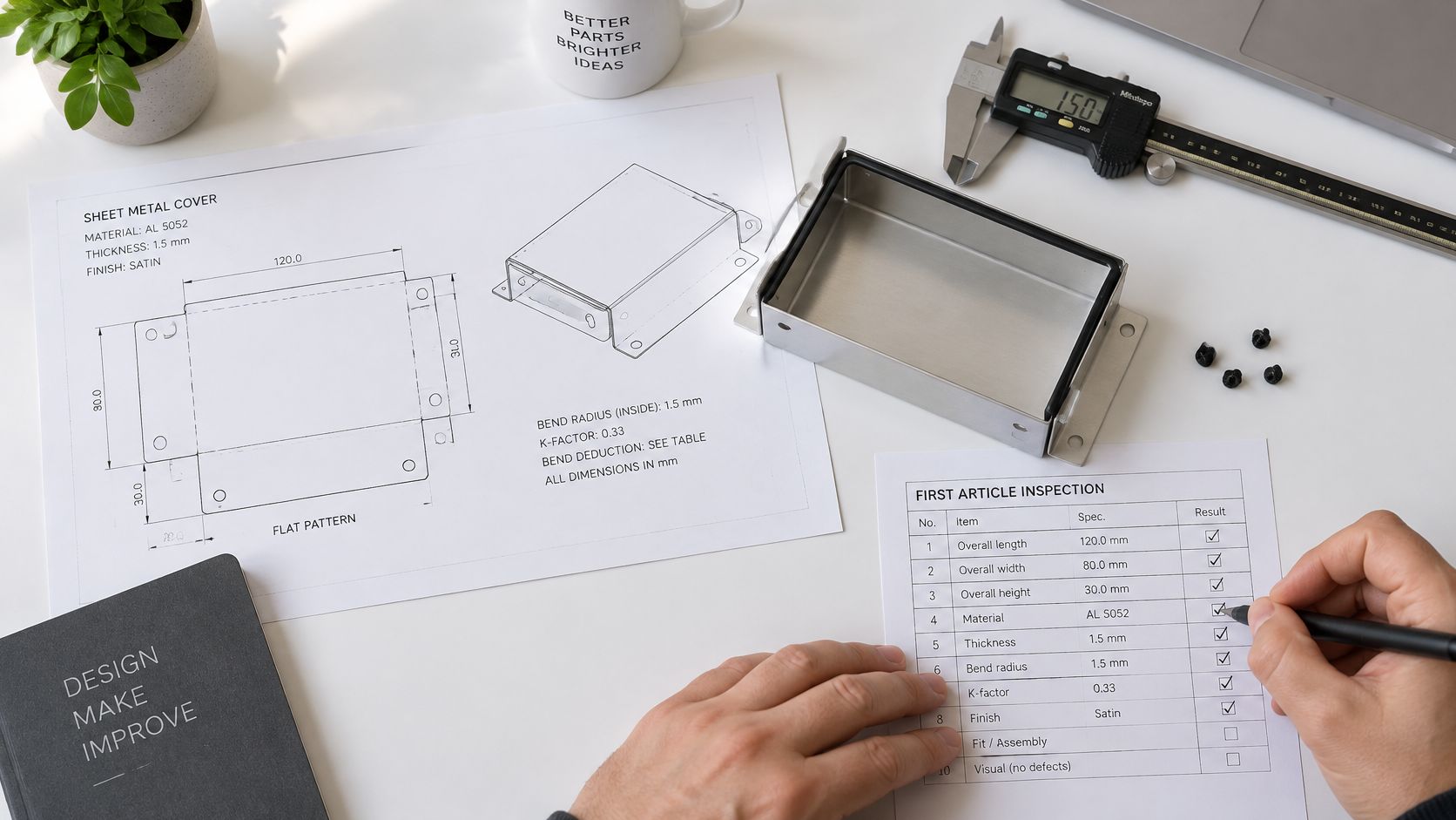
A DFM review earns its keep here. At FIRMFG we run sheet metal fabrication in aluminum, brass and stainless steel with no minimums, and the process runs from design review through prototyping, optimization and production, so bends, holes and tolerances get examined against real tooling before anything is cut.
Order one first article with the actual fasteners, gasket and finish, then assemble it and measure fit. A bare-metal sample tells you nothing about whether the door still closes after powder coat, which is the failure mode that shows up after you've committed to fifty units.
Send the CAD and drawing for prototype sheet metal fabrication review this week, while the geometry is still soft. A DFM pass costs you a day now and saves a revision cycle later.
The coupled decisions in this article are the ones FIRMFG's engineers review most often: IP target against gasket groove, heat load against vent area, grounding path against finish masking. FIRMFG offers free DFM feedback on your CAD files, with engineers reviewing bends, holes and tolerances and returning suggestions before the first cut, plus sheet metal fabrication in aluminum, brass and stainless steel with no minimums. Send your enclosure model and drawing to FIRMFG and get a manufacturability review back before you commit to a run.