Sheet Metal Punching Guide for Burrs and DFM
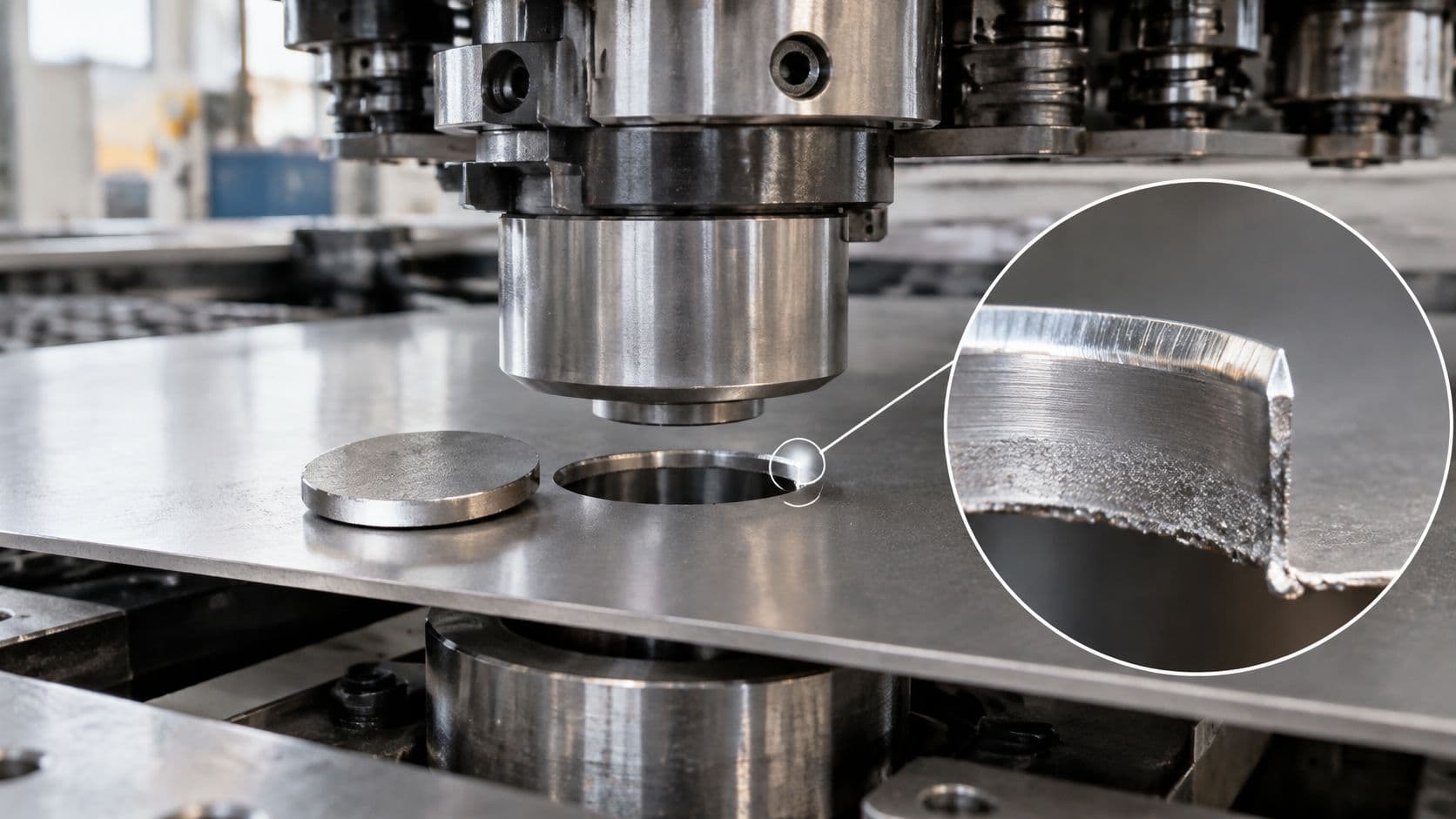
A connector flange can pass a dimensional check and still leak at assembly. The hole centers are right, the flange sits flat, and the gasket fails because the punched edge isn't a clean cylinder. For a hardware designer, that's the difference between drawing a hole and specifying a reliable edge.
Table of Contents
Turret Tools Versus a Dedicated Die
Burrs Distortion and What to Call Out
Secondary Steps on Real Punched Parts
Qualify the Part Before You Release It
What the Punch Leaves on the Edge
Sheet metal punching drives a punch through sheet into a matching die. The punch separates a slug, leaving a hole, slot, louver, nibble contour, or shallow formed feature. But the cut edge isn't one uniform surface. Follow it from the punch face toward the die side and you'll find four zones: rollover, where the sheet yields as the punch enters; a burnished or sheared band, where the punch cuts the material; a fractured zone, where cracks from the punch and die meet; and a burr at the die-side exit.
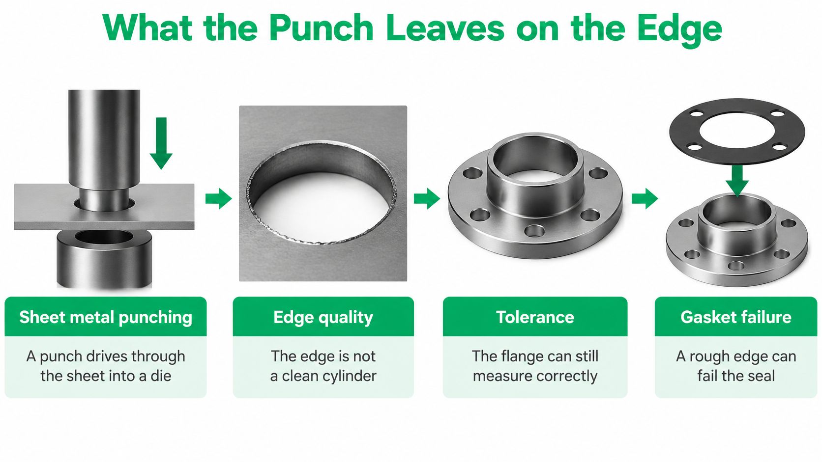
That edge profile can matter more than the measured hole diameter. A burr facing a gasket can scratch or interrupt the sealing contact. On a sliding fit, it can catch during assembly. On an enclosure seam, it can prevent two surfaces from seating cleanly. A sharp fractured edge may also be visible beneath powder coat or anodizing, or cause coating damage where the finish must wrap around a cutout.
A single punch that cuts the full perimeter generally leaves a continuous wall. Nibbling takes a different approach: overlapping hits build a larger opening or contour, leaving small scallops along the edge. That can be perfectly acceptable for a hidden clearance opening, but a visible or sealing edge may need another process to smooth it.
Clearance helps determine how the edge forms. If cracks from the punch and die meet cleanly, the fractured zone is more controlled. If they don't, the edge can show a broader fracture, more rollover, or greater variation. The useful question isn't just whether the feature can be punched. It's which combination of material, clearance, burr direction, and finishing will make the edge work in the assembly.
Punching Limits and Material Overrides
Start with the row that matches the actual alloy and sheet thickness, not a default rule on a shop drawing. These values are design starting points, not universal acceptance limits. Alloy, temper, tool condition, lubrication, clearance, and the functional edge requirement all affect the result.
| Material | Min hole diameter | Ligament and nearby features | Total clearance | Practical note |
|---|---|---|---|---|
| Mild steel | About 1.2 × thickness | About 1.5–2 × thickness | 2–5% for small rollover; 20–25% for a smaller burr | Reference alloy for the force estimate |
| Stainless steel | About 1.5–2 × thickness | About 2 × thickness | Start tighter than the large-rollover band, then validate | Work hardens and raises tonnage |
| High-strength steel | About 1.5–2 × thickness | About 2 × thickness | Validate; don't copy mild-steel dies | Shear strength can exceed turret capacity |
| Aluminum | Use a representative first-piece trial | About 1.5 × thickness | Often a larger percentage because the sheet is soft | Galling and smear if the punch is dry or dull |
| Brass and copper | About 1 × thickness | About 1.5 × thickness | Moderate; confirm burr direction | Soft alloys can leave tall die-side burrs |
The clearances in the steel row illustrate why a single “best” setting doesn't exist. A technical bulletin on punching and piercing steel sheet and strip reports that total clearance of approximately 2–5% of sheet thickness produces minimal rollover but a relatively large burr. At 20–25%, the cut depth decreases and the burr gets smaller, but rollover increases. Tight clearance can raise compressive load, promote secondary shearing, and accelerate tool wear. Excessive clearance can widen the fracture angle and increase dimensional variation.
A published punching process guide likewise describes minimum-hole guidance near 1.2 times thickness for some materials, while stainless and high-strength materials may call for about 1.5–2 times thickness. Treat those ratios as a first screen. Classify the feature as cosmetic, structural, or assembly-critical, define the acceptable burr direction, and qualify a first piece made from the production alloy. A nominal hole tolerance of approximately ±0.1 mm for small holes or spacing tolerance of approximately ±0.2 mm may be achievable under a qualified process, but don't assume the drawing tolerance controls edge quality.
Estimate the press load
Use the same example feature you checked in the table to assess whether the press can cut it. The first-order estimate is F = L × t × τ, where L is the perimeter being sheared at once, t is sheet thickness, and τ is the material's shear strength. With millimetres and N/mm², the result is newtons; divide by 1,000 to get kilonewtons. A sheet-metal punching force guide describes this estimate and recommends allowing for stripping and friction, then applying a safety margin.
For a round hole, use its circumference for L. For a cluster of features hit together, use the total perimeter engaged simultaneously. That distinction matters: a legal hole diameter doesn't guarantee that a cluster of holes fits the machine's tonnage. If the peak load is too high, stagger punch heights or sequence the hits to reduce simultaneous engagement without changing the finished geometry.
Stainless and high-strength grades can work-harden, so don't transfer a mild-steel die choice without a trial. Aluminum needs attention to punch condition and lubrication because galling and smeared material can spoil the edge. Very thin sheet can distort between closely spaced features; thick sheet can exceed press capacity. Inspect a sectioned first piece from the actual material before approving the full nest.
Turret Tools Versus a Dedicated Die
For a flat prototype or an NPI part with varied holes and slots, a turret punch can accommodate layout changes without building a new die for every feature. A rotary magazine holds multiple punches above matching dies. Numerical control positions the sheet and selects tools within one setup, so revisions may require a program change or tool selection rather than dedicated tooling. That flexibility comes with a trade-off: each feature still depends on the selected tool and its clearance.
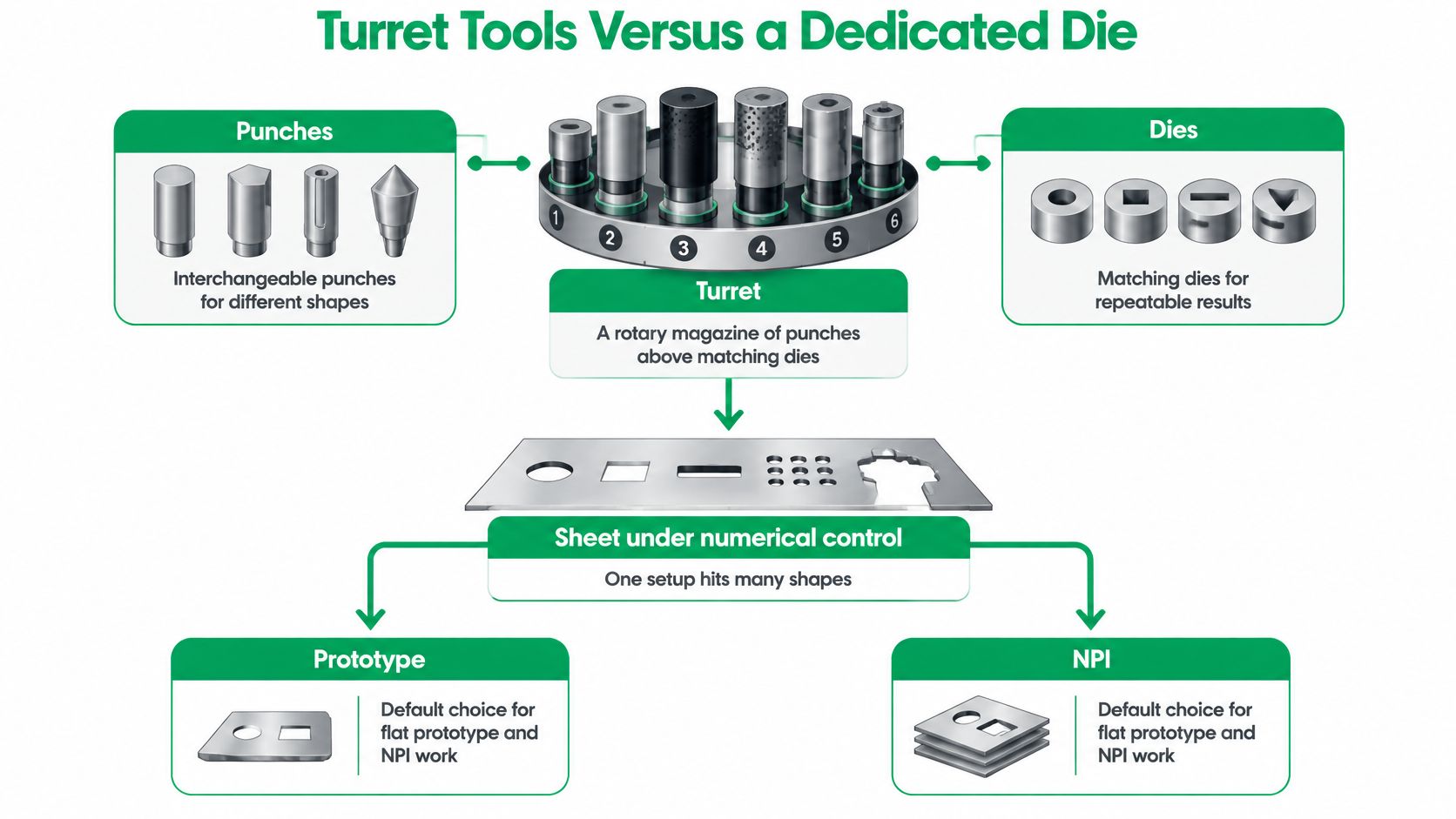
Turret punching developed alongside the shift from manually operated presses to numerically controlled systems. By the 1970s, turret punches could selectively engage different tools, as described in the patent record for a turret-punch system. Later developments addressed automatic loading and tool exchange. The result is a process suited to repeated features and changing layouts, while a dedicated punch-and-die set can make more sense when the design and production requirements are stable.
| Option | Changeover | Edge quality and trade-off |
|---|---|---|
| Turret punch | Suits mixed features and design revisions | Edges depend on the selected tool's clearance |
| Nibbling | Builds contours from repeated hits | Leaves scallops; smooth the edge if appearance or sealing matters |
| In-turret forming tool | Adds features without a separate forming setup | Can form louvers, embosses, countersinks, or shallow extrusions; forming height and nearby distortion constrain placement |
| Dedicated punch-and-die set | Requires dedicated tooling but suits a stable design | Can suit repeated parts when cycle time justifies the tooling |
Cluster punches cut a pattern in one stroke, reducing individual hit count while increasing the load applied at once. Check the press capacity against the simultaneous cutting perimeter before committing to the layout.
Choose a turret when feature variety and revision speed matter more than dedicated tooling. Choose a dedicated die when the blank is stable, production repeats, and cycle time justifies the setup. For parts that combine punching with a broader stamping process, FIRMFG offers sheet metal stamping.
Burrs Distortion and What to Call Out
A drawing note that says “deburr all edges” can add unnecessary labor, round functional corners, or shift dimensions. Specify edge treatment by function: an internal edge that does not contact an operator, seal, sliding surface, or coating may need no finishing, while a gasket lip or exposed flange may need a controlled edge condition.
Call out maximum burr height, permitted direction, which edges are affected, and whether acceptance is visual or tactile. State how the feature will be inspected. A gasket interface may need the burr directed away from the seal; an operator-contact edge should feel smooth. A hidden internal opening may need no secondary finishing.
| Symptom | Usual cause | Fix |
|---|---|---|
| Tall die-side burr | Dull punch, or clearance at the tight end of the range | Resharpen the punch; open clearance toward 20–25% where extra rollover is acceptable, or cap burr height on critical edges |
| Large rollover, short burnish | Clearance near 20–25% of thickness | Tighten clearance if a longer burnished wall is required |
| Secondary shear and fast wear | Clearance too tight | Open clearance and check lubrication |
| Oil-can or oval holes | Ligament under about 1.5–2 × thickness, or too much perimeter at once | Widen spacing and stagger punch heights |
| Size drifts through the run | Worn punch or die, not the drawing tolerance | Qualify a first piece and set a tool-life check |
| Scalloped opening | Nibbled contour | Leave it if hidden; machine or laser the edge if it seals or shows |
Use the table to narrow the cause, then check the actual part. A tall burr may call for punch sharpening, a clearance adjustment, or a specified finishing operation. Choose the least costly correction that protects the feature's function. The clearance trade-off matters: moving toward 20–25% can reduce burr size but increases rollover, while tighter clearance can lengthen the burnished wall and raise burr risk. A universal hole or edge rule fails when material and coating change; define acceptance for the actual part.
Rams, pinch points, stored energy, sharp sheet edges, and ejected slugs are shop-floor hazards. Guarding, interlocks, lockout, training, and inspection belong to machine safety controls and local rules, not to a drawing note.
Procurement check: Confirm whether the quote includes the specified edge condition or only the primary punching operation.
Secondary Steps on Real Punched Parts
A process stack should describe what happens to the flat blank, which edges get attention, and what follows punching. Consider three common parts.
An electronics enclosure starts as a flat blank. Punch the connector pattern and ventilation openings before bending, keep the burr inside where practical, and limit burr height at the gasket lip. Then bend and assemble the enclosure. A tall burr won't disappear under powder coat, and a sharp fractured edge can compromise the finish at a critical interface.
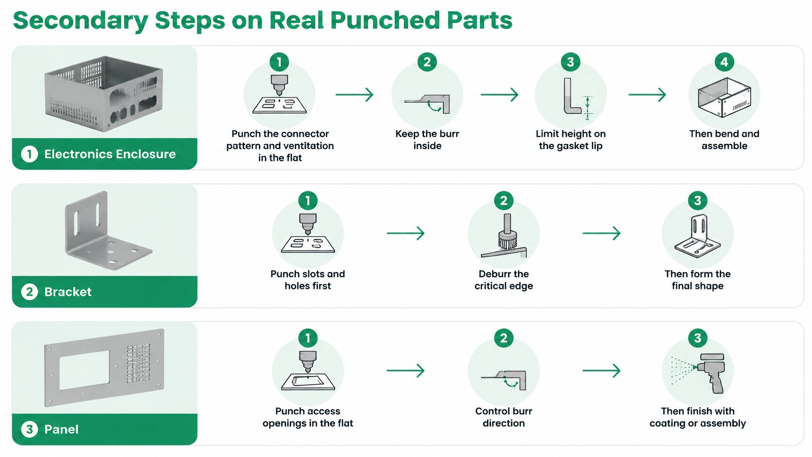
A mounting bracket also benefits from flat-blank processing: punch slots and clearance holes, deburr only the edges that need it, then form the bracket and install hardware or weld it. Keep features away from bend lines where the geometry allows, and check whether nearby holes will distort during forming. If a design needs an extruded hole to engage a fastener, a plain punched hole won't provide the same feature.
For a louvered panel, form the louver in the turret, then deburr the operator-facing perimeter. The hidden edges can remain untouched if they're safe and don't interfere with assembly or finishing. If you need help choosing a tool for a targeted edge-finishing step, see this guide to what a deburrer does.
A practical order is punch and form while flat, selectively deburr, bend, add welds or hardware, then finish. Keep features that strain press capacity, require tighter position control than the qualified process can hold, expose a cosmetic fractured edge, or form a seal face out of the punch process. Laser cutting or machining can handle those critical features while punching produces the repeated pattern economically.
Write that sequence on the drawing or process specification. “Punched part” alone doesn't say whether it includes edge finishing, forming, hardware, welding, or coating.
Qualify the Part Before You Release It
Before you request a quote, make the drawing and process expectations agree. A short release check prevents a nominally correct hole pattern from arriving with the wrong material, edge orientation, or finishing scope.
- Match material and thickness: Identify the alloy and measured sheet thickness, then use the corresponding row in the limits table as a starting point.
- Set clearance intent: Say whether the priority is small rollover or a smaller burr, and require qualification on the actual material.
- Define each critical edge: Specify burr height, permitted direction, affected edges, and visual or tactile acceptance.
- Check feature spacing: Review minimum holes, ligaments, nearby features, and bend proximity; flag any design override and its reason.
- Check peak load: Calculate the simultaneous perimeter and estimate force, then note whether the hit sequence or staggered punch heights need to change.
- Name every downstream operation: State which features are punched, selectively deburred, bent, welded, assembled, or finished. Ask the quote to identify which steps are included.
If the part needs forming after punching, include the intended sequence and bend requirements in the released package. FIRMFG offers sheet metal bending, stamping, welding, enclosures, and prototyping, and provides fabrication in aluminum, brass, and stainless steel with no minimums. For a short run, send the flat pattern and edge callouts for DFM feedback on clearance, tonnage, and which edges need finishing. The sheet metal bending service is one part of that process stack.
FIRMFG offers sheet metal fabrication including laser cutting, bending, surface treatment, stamping, welding, and prototyping, with aluminum, brass, and stainless steel options and no minimums. Send your flat pattern with material, clearance intent, and functional burr callouts, then visit FIRMFG to discuss a manufacturable process stack for your punched part.