CNC Lathe Machining: Speeds, Feeds and Tolerances
You've got a shaft drawing ready to quote, but the prices come back far apart. One shop proposes straightforward turning; another adds live tooling, extra inspection and a finishing operation. The difference may not be the hourly rate. It may be how each shop interprets your material, mating diameters and setup requirements.
CNC lathe machining is economical when the drawing, cutting conditions and inspection plan work together. A diameter that's easy to make on a prototype can become a scrap risk during production. Before comparing quotes, work out which features need precision, how the machine will reach them and what evidence will show that the batch meets the drawing.
Table of Contents
- How a CNC Lathe Turns Stock into a Part
Follow the cut from the face to the cutoff
Establish control before releasing the batch
Starting Speeds and Feeds for Common Materials- Starting approach by material for carbide turning
Which Lathe or Other Process Fits the Part- Lathe types and the features each one handles
Tolerances and Surface Finish You Can Hold- Typical turned tolerances and surface finish
Design Rules That Keep Turned Parts Affordable- Make the geometry compatible with standard tools
What to Send for a Turning Quote- Make the design review actionable
How a CNC Lathe Turns Stock into a Part
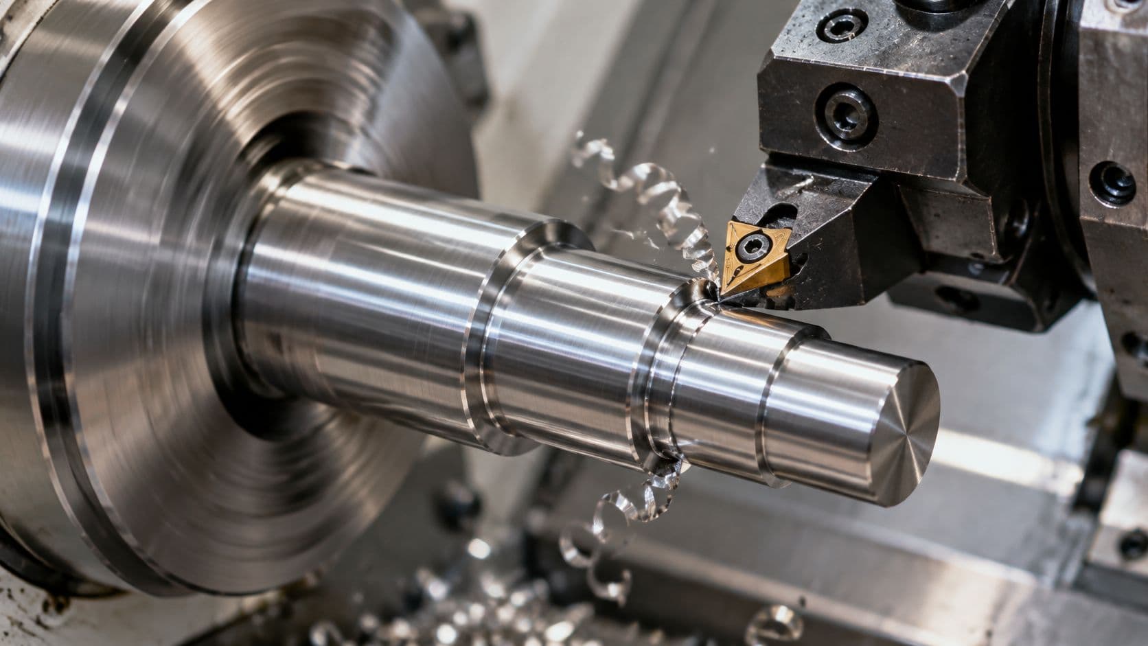
A round bar sits in the chuck. By the time the cycle finishes, a stepped shaft with a groove and threaded end is ready to separate from the stock. The machine gets there by spinning the workpiece while a single-point cutting tool travels along it.
The tool moves on X to control diameter and Z to control length. It's similar to a potter's wheel, except programmed coordinates replace the hands and a sharp tool removes metal. The tool peels material away around the circumference, producing chips rather than necessarily forming complete rings.
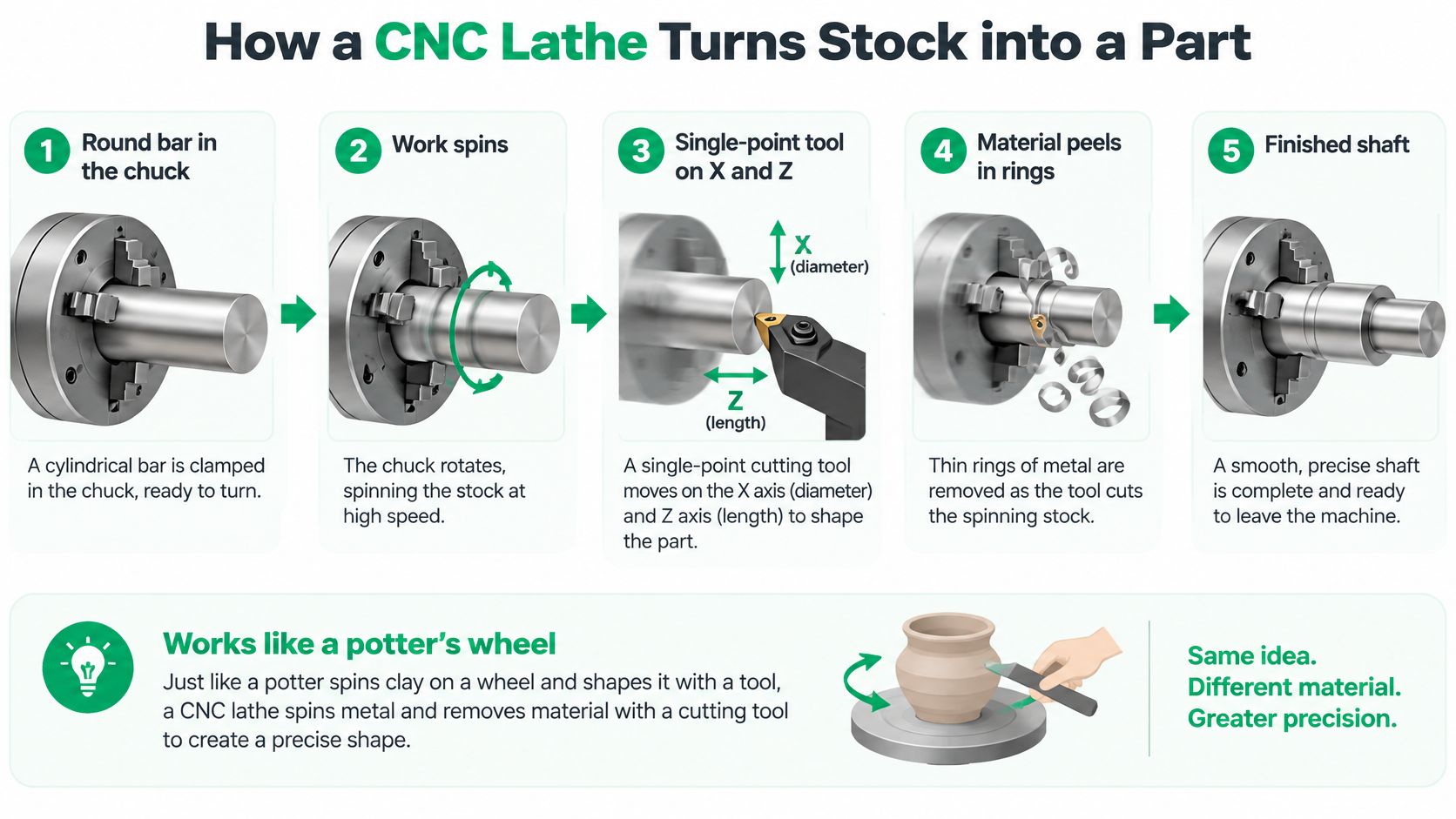
Follow the cut from the face to the cutoff
For a typical shaft, the program directs the following operations:
- Face the end to establish a clean reference surface.
- Rough turn the stock, leaving material for final sizing.
- Finish turn the functional diameters and shoulders.
- Groove where a seal, retaining ring or relief requires it.
- Thread the specified end or section.
- Part off the completed component from the remaining bar.
G-code supplies the coordinates, feed commands and operating instructions. In milling, the cutter rotates and the machine positions the workpiece relative to it. For a part whose main features are symmetrical about an axis, turning is usually the first process to evaluate.
Establish control before releasing the batch
The shop first locks down the material, datums and mating diameters. Next, the machinist selects a chuck, collet or guide-bushing arrangement, limits unsupported stock and loads the tools and offsets.
The programmer proves the path in single block, checks clearances and confirms that roughing leaves suitable finishing stock. Final sizing follows machine stabilization, and the critical diameters get checked before production continues.
The scale of the equipment market reflects how established this process is: Business Market Insights valued the global CNC lathes market at USD 9.10 billion in 2024. For an individual buyer, though, the useful question is simpler: can the chosen setup reach every important feature without losing its reference?
Starting Speeds and Feeds for Common Materials
Calculate spindle speed from cutting speed and the diameter being cut:
Spindle speed in rpm = cutting speed in m/min × 1000 ÷ (π × diameter in mm).
As a hypothetical calculation, selecting a cutting speed of 400 m/min for a 50 mm diameter gives approximately 2,550 rpm. That demonstrates the conversion, not a recommended setting for an unidentified material or insert.
Start with the cutting-tool supplier's range for the exact alloy, hardness, insert grade and operation. A generic material name isn't enough: a soft, free-cutting condition and a hardened condition shouldn't share a starting program.
Starting approach by material for carbide turning
| Material | What changes the start | First adjustment |
|---|---|---|
| Aluminum | Often permits fast cutting; built-up edge can spoil the finish | Reduce feed per revolution if Ra fails, after checking the edge |
| Free-machining brass | Chips generally break readily with low cutting force | Keep a positive cut so the tool doesn't rub |
| Mild steel such as S45C | Feed strongly influences roughness; speed also changes temperature | Reduce feed first, then refine depth of cut |
| Alloy steel | Hardness, insert grade and setup rigidity govern the start | Begin at the low end of the supplier's applicable range |
| Stainless steel | Heat and work hardening make an unstable cut costly | Lower speed when necessary and maintain a cutting feed |
| Titanium Ti-6Al-4V | Heat concentrates near the cutting edge | Lower speed and inspect discolored chips alongside tool wear |
| Engineering plastic, including POM or acetal | Sharpness and chip clearance help prevent smearing | Use a controlled finishing depth and avoid dwelling |
These are starting approaches, not universal cutting values. For aluminum-specific decisions about alloy, geometry and chip control, use the CNC aluminum machining guide alongside the insert manufacturer's recommendations.
Separate stock removal from surface generation
Roughing prioritizes material removal with a feed and depth the machine, insert and workholding can sustain. Finishing prioritizes the required size and texture. Slowing every movement wastes time without necessarily improving either.
In experimental turning of S45C steel with coated carbide, feed was the most significant roughness factor, while higher cutting speed increased temperature but improved roughness within the tested range. A smaller cutting depth also improved finish.
When Ra fails, reduce feed per revolution first, provided the edge is cutting. Then refine speed and finishing depth. An excessively shallow pass can rub against the surface, especially with a worn edge or unsuitable edge preparation.
Practical rule: Don't use a lighter cut to compensate for a blunt insert or an unstable setup.
For an unfamiliar material, begin conservatively within the supplier's range. With stainless steel and titanium, resist increasing speed to recover cycle time before checking heat and edge condition. Keep enough feed to shear material rather than repeatedly burnishing it.
During the first cut, watch for chatter, built-up edge, unexpected chip discoloration and poor chip evacuation. Chip color alone isn't a pass-or-fail test; interpret it with tool wear, coolant delivery and dimensional results. Record the actual cycle time too, because a technically acceptable cut can still miss the quote's economics.
Which Lathe or Other Process Fits the Part
Start with a shaft that has turned bearing seats, a cross-hole and opposing flats. Its cylindrical surfaces suit a lathe, but the hole and flats determine whether basic turning is enough. Choose the machine around the complete feature set, not just the outside shape.
A basic lathe can produce the rotational features, followed by a separate milling setup for the hole and flats. A live-tool lathe may complete those features while retaining the same grip. That difference affects fixtures, handling and the relationship between the hole and the turned axis.
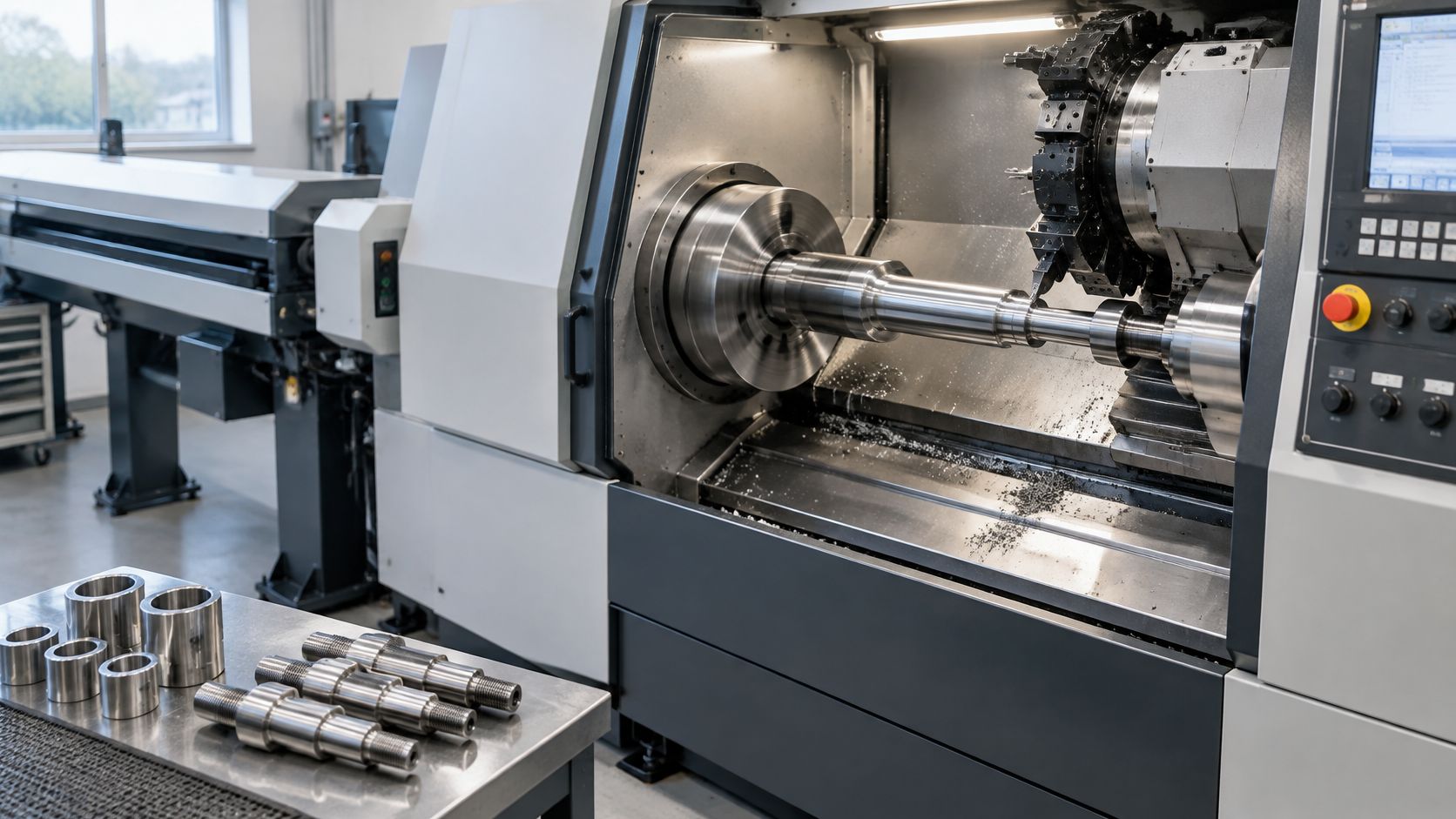
Lathe types and the features each one handles
| Machine type | Added capability | Typical features | Best for |
|---|---|---|---|
| Two-axis CNC lathe | X and Z motion for conventional turning and axial operations | Turret, with optional bar feeder | Shafts, bushings and threads |
| Lathe with live tooling | Driven tools machine holes and flats | Driven tool holders and C-axis positioning | Cross-holes and flats on round parts |
| Multi-axis mill-turn center | Y-axis milling and, when equipped, sub-spindle transfer | Off-center machining and back-side access | Complex parts completed without a manual transfer |
| Swiss-type lathe | Guide bushing supports suitable bar stock near the cut | Sliding headstock | Small, long, slender precision parts |
A conventional turret lathe also drills and bores along the spindle axis. It doesn't need live tooling for every hole. The distinction is whether the feature requires a rotating driven tool or positioning beyond conventional turning motion.
For the example shaft, live tooling is attractive when the cross-hole must stay accurately located relative to the bearing seats. The C-axis positions or controls the workpiece's rotation while a driven drill or end mill cuts the non-rotational feature. Tool access still matters, so a live-tool machine isn't an automatic promise of complete machining.
Pay for useful capability, not unused axes
Consider a hydraulic piston with a cross port. If the port is accessible in the turning grip, live tooling can avoid a separate fixture. If the back face also needs machining, sub-spindle transfer may let the machine complete it without an operator flipping the part.
A mill-turn center becomes more useful as features spread across faces or require off-center access. Its hourly rate may be higher, but the buyer should compare total setup, machining, handling and inspection cost. The turn-mill machining guide explains how that combined workflow differs from separate turning and milling.
Swiss-type machining solves a different problem. Its guide bushing supports compatible stock close to the cut, helping control deflection on slender components. Bar quality, bushing clearance and the planned cutting sequence become important, so Swiss machining isn't a more accurate substitute for every chucking job.
A gearbox housing, by contrast, is generally a milling job. Large cavities, mounting faces and distributed holes don't become economical turning features just because the part contains a bore.
Count tools and transfers before comparing rates
A practical turning tool list may include CNMG or DNMG inserts, a finishing tool, a boring bar, a grooving insert and a threading tool. Live-tool work adds driven drills, taps or end mills. Each turret index and approach move consumes time, so unnecessary tool changes deserve attention.
A stronger insert shape can support roughing, while a more accessible shape helps reach shoulders and profiles. A larger nose radius may strengthen the edge, but it also changes cutting forces and can aggravate chatter on a flexible part. Select the nose geometry with the workpiece stiffness, not in isolation.
A cheaper machine hour isn't a cheaper part if the job needs another fixture, another transfer and another inspection.
Turning followed by cylindrical grinding is justified when hardness, geometry or finish requirements exceed the proposed turning process. It adds another operation and datum-transfer risk, so don't specify it by habit. For short runs, eliminating a dedicated fixture can outweigh a higher machine rate; for repeat production, a dedicated cell may justify the development effort.
Tolerances and Surface Finish You Can Hold
Prototype capability isn't process capability. A shop that makes one correct sample has shown it can reach a dimension. It hasn't shown the process will stay centered across a run.
The CNC turning guide from ISO CNC places conventional turning around IT7–IT9, with typical diameter tolerances of approximately ±0.01–0.05 mm. Use that band as a planning reference for diameter features, then qualify anything tighter against the actual setup, material and inspection method.
Typical turned tolerances and surface finish
| Feature | Realistic band | What usually breaks it |
|---|---|---|
| Outside diameter | ±0.01–0.05 mm in conventional turning | Thermal drift, insert wear and clamping distortion |
| Bore diameter | ±0.01–0.05 mm as a starting point; tighter needs a proven boring setup | Bar deflection, chip packing and heat |
| Overall length | Generally looser than the diameter bands; define the face datum that controls it | Datum transfer and turret growth |
| External thread | Set by the thread standard and fit class stated on the drawing | Insert wear, spring and incomplete thread form |
| Surface finish | A measurable Ra value specified on the functional surface | Feed per revolution, vibration and edge condition |
A surface can look smooth and still fail its dimensional requirement. A diameter can also measure correctly while its texture damages a seal or prevents the intended bearing contact. Ra describes surface texture, not dimensional accuracy, and it doesn't replace requirements for roundness, runout or waviness.
Use the surface roughness chart to interpret finish terminology, then specify the actual functional surface and measurement requirement. Don't add grinding or polishing just because the drawing asks for a smooth appearance. First confirm whether the turning process can hold the required texture without changing the geometry.
Control the run, not just the first inspection
A cold check can pass while later parts drift as the spindle, bearings, turret and surrounding structure heat up. In a validated CNC-lathe compensation example published in The International Journal of Advanced Manufacturing Technology, batch machining error fell from 18.3 μm to 4.5 μm.
The practical controls are straightforward:
- Warm up consistently: run a repeatable routine before final sizing.
- Monitor influential temperatures: track the assemblies that move the tool-to-workpiece relationship.
- Measure during sustained cutting: check critical dimensions after the machine reaches working temperature.
- Track wear separately: a deteriorating edge shouldn't hide behind repeated offset changes.
- Define acceptance: state the gauge, the measurement condition and the response to an out-of-band result.
Thermal compensation helps most when it distinguishes spindle and turret movement rather than treating every displacement as the same error. It still doesn't remove the need for a stable setup and meaningful inspection.
For a hypothetical fit calculation, give a shaft and its mating bore a tolerance of ±0.02 mm each. Their combined clearance variation can reach ±0.04 mm around nominal when the errors oppose each other. The fit must be evaluated as an assembly, not as isolated acceptable dimensions.
Tighten the dimensions that control mating or function. For the rest, choose an applicable general tolerance standard and confirm it covers the drawing's features.
Design Rules That Keep Turned Parts Affordable
An affordable turned part gives the tool a clear path, supports the work during cutting and avoids features that require special tooling without a functional benefit. Start with geometry rather than asking the shop to solve every difficulty through slower machining.
Make the geometry compatible with standard tools
- Match internal corners to an available tool nose. A perfectly sharp internal corner is incompatible with a radiused turning edge. Allow a practical radius or provide relief where the mating component needs clearance.
- Plan deep bores around boring-bar stiffness. Keep the tool as short and well supported as the geometry allows. If a deep bore is essential, allow room for an appropriate bar and chip evacuation rather than treating depth as free.
- Choose grooves around standard inserts. An unusually narrow or awkwardly placed groove may require a special tool and restricted cutting conditions. Confirm that the groove width and corner form are functional before freezing them.
- Give threading tools an exit. Relief undercuts and entry chamfers help the tool form the required thread cleanly. Define usable thread length so the machinist doesn't have to guess whether runout is acceptable.
- Support thin walls through the cutting sequence. Leave stock where it provides stiffness, and consider how the chuck will distort the final wall. A dimension measured under clamping pressure may change after release.
- Reserve close tolerances for functional features. Use a suitable general standard elsewhere and identify exclusions clearly. General tolerances shouldn't conflict with explicit geometric or fit requirements.
- Choose a machinable grade when service conditions allow it. Compare suitable aluminum, free-machining brass or free-machining steel options against strength, corrosion and regulatory requirements. A material substitution is only useful if the finished part still does its job.
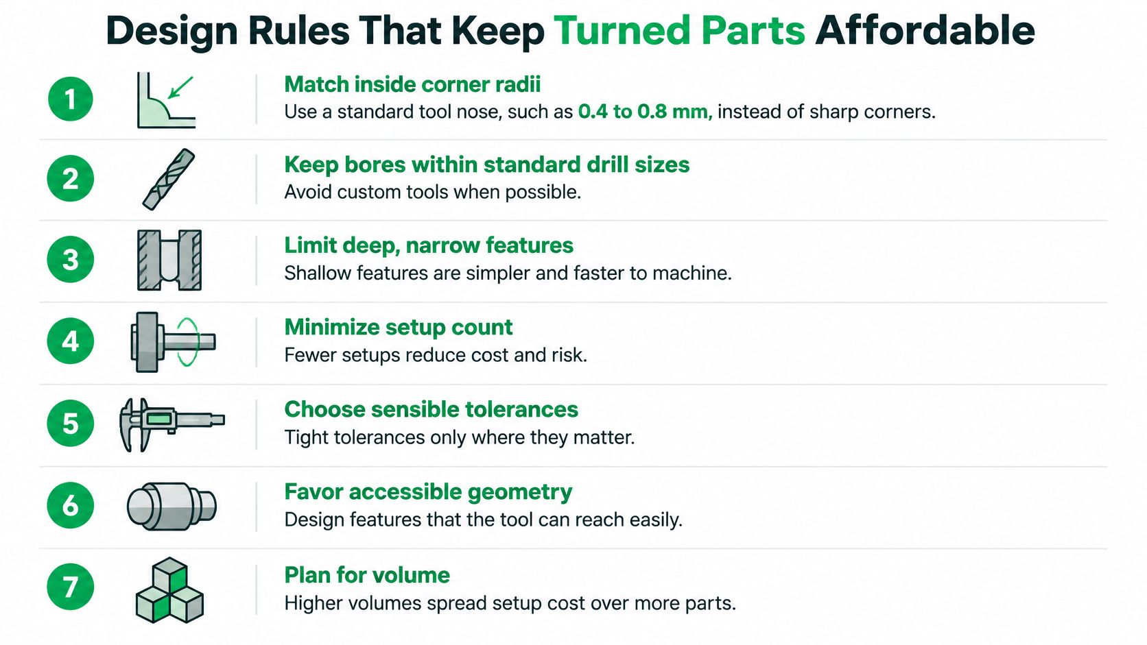
Review the drawing as a manufacturing instruction
Before release, check tool access, gripping surfaces and which features must remain related in the same setup. A groove hidden behind a shoulder or a bore with no chip escape can cost more than its size suggests.
Drawing review: If removing a requirement wouldn't change fit, life, safety or assembly, question whether it belongs on the drawing.
Unnecessary precision can require slower cycles, additional finishing, tighter temperature control and more rejected parts. The right design isn't the loosest possible drawing. It's the drawing that assigns manufacturing effort to features that improve product performance.
What to Send for a Turning Quote
Send a package that lets the shop price the actual job rather than choose assumptions on your behalf. A CAD model defines shape, but it rarely communicates every acceptance requirement.
- Material and grade: Include the required condition, heat treatment and any substitution restrictions.
- Quantity and release pattern: Distinguish the immediate prototype order from expected repeat batches.
- Critical diameters: Identify mating surfaces and their functional tolerances.
- Surface texture: Put Ra requirements on the surfaces where texture affects performance.
- Thread callouts: Include the standard, size, pitch, fit class and usable engagement.
- Datums: Show how the part is located in its assembly and how related features should be inspected.
- Inspection level: State whether you need a dimensional report, material documentation or specific functional gauging.
- Processing restrictions: Identify coatings, coolant limitations, cleanliness requirements and prohibited materials.
Make the design review actionable
A useful design-for-manufacture reply names the feature, explains the constraint and offers a choice. It might identify a corner that needs a different radius, a deep bore requiring special tooling or a tolerance that adds inspection without improving the fit.
Keep the model and drawing synchronized. If they disagree, identify which document governs before quoting, and make sure finish allowances or post-treatment dimensions are clear. Otherwise, competing shops may price different interpretations of the same part.
For unattended production, ask how the proposed process handles chips, worn tools and inspection stops. A fast nominal cycle isn't a reliable cost basis if an abnormal cut can continue producing scrap. The quote should reflect saleable parts and necessary controls, not spindle time alone.
Release the package with functional requirements marked
Before uploading, mark the dimensions that control assembly and explain any requirement that isn't obvious from the geometry. Include the mating condition where it helps, particularly for sealing surfaces, bearing seats and threaded connections.
We provide a free CNC machining quote within 24 hours after CAD files are uploaded. A complete drawing package lets us evaluate the manufacturing route with fewer assumptions and make the trade-offs visible before you commit.
FIRMFG offers CNC turning, CNC milling and 5-axis CNC machining for metal and plastic components. Visit FIRMFG to upload your CAD model and drawing with functional diameters, material grade and inspection requirements marked, so the quote addresses the part you need.