Turn Mill Machining Explained for Engineers
A rotational component arrives at inspection with a familiar problem. The turned diameter is correct, but the off-axis holes are slightly out of position because the part moved from a lathe to a mill, was reclamped, and picked up another layer of fixture and alignment error. The machining quote looked reasonable until the team added handling, inspection, programming, and the delay caused by moving work between machines.
That is where turn mill machining earns serious consideration. A mill-turn center combines turning and milling in one CNC-controlled workflow, but its value isn't automatic. The right question is not whether the machine can perform more operations. It's whether the part has enough geometric complexity, setup risk, or inspection sensitivity to justify the added programming and process-control burden.
Table of Contents
- The Single-Setup Advantage for Complex Parts
Why fewer handoffs matter
Where the advantage is strongest
How Hybrid Turn-Mill Centers Operate- The main spindle establishes the primary reference
Technical Capabilities and Precision Limits- Process geometry controls the finish
Turn-Mill vs Separate Lathe and Mill Workflows- The break-even question
Hidden Costs and Programming Risks- Postprocessors are part of the process
DFM Guidelines for Multitasking Machining- Place features where the machine can reach them
Sourcing Prototypes and Low-Volume Production- Match the workflow to the part family
The Single-Setup Advantage for Complex Parts
Consider a precision shaft with turned journals, a milled flat, cross-drilled holes, a threaded end, and a compound contour near the shoulder. A conventional route might turn the main diameters first, transfer the part to a mill for the flat and holes, then return it to another fixture for backworking. Every transfer creates another opportunity to lose the relationship between the original spindle axis and the secondary features.
A turn-mill center changes the sequence. The machine can turn the cylindrical surfaces, index the spindle, use live tooling for milling and drilling, and complete additional features while the part remains referenced in the same machine environment. That single clamping doesn't eliminate every source of error, but it removes a major class of errors caused by repositioning the workpiece.
For engineers who need a concise foundation, this overview of CNC turning and its role in rotational machining is useful. Turning remains the efficient choice for circularly symmetric geometry. The hybrid approach becomes more compelling when that geometry carries features that a lathe alone can't reach.
Why fewer handoffs matter
The practical gain is not only fewer machines on the routing sheet. It includes fewer setup instructions, fewer opportunities to select the wrong work offset, less handling damage, and a shorter chain of dimensional relationships for the quality team to verify.
A part with a critical hole pattern referenced to a turned diameter illustrates the point. In separate setups, the machinist must establish the hole location from a fixture or probing routine that relates back to the turned axis. In a mill-turn process, the same spindle reference can govern both operations, provided the machine kinematics, workholding, and program are validated correctly.
Practical rule: A single setup is valuable only when the retained reference is more reliable than the secondary fixture would be.
Turn-milling emerged as CNC control made it practical for one machine to coordinate turning and milling rather than relying on separate manual operations. Industry coverage places major adoption in the 1980s and 1990s, when CNC technology enabled practical control of simultaneous multi-operation machining, according to this history and technical guide to turn-milling. That development shifted many complex parts toward multitasking centers, particularly in high-precision sectors such as aerospace and defense.
Where the advantage is strongest
The strongest candidates usually share several characteristics:
- Rotational primary form: The part starts as a shaft, sleeve, hub, flange, or other turned component.
- Off-axis features: Holes, slots, flats, or pockets must be machined at a controlled angular or radial relationship.
- Backworking requirements: The second end needs drilling, threading, facing, or contouring after the main turning operations.
- Compound geometry: Multiple transitions or contours make repeated fixturing less attractive.
- High error cost: A positional mistake can force rework, scrap, or a lengthy investigation.
A simple turned spacer with one face and one diameter probably doesn't need a hybrid center. A rotational housing with intersecting features often does.
How Hybrid Turn-Mill Centers Operate
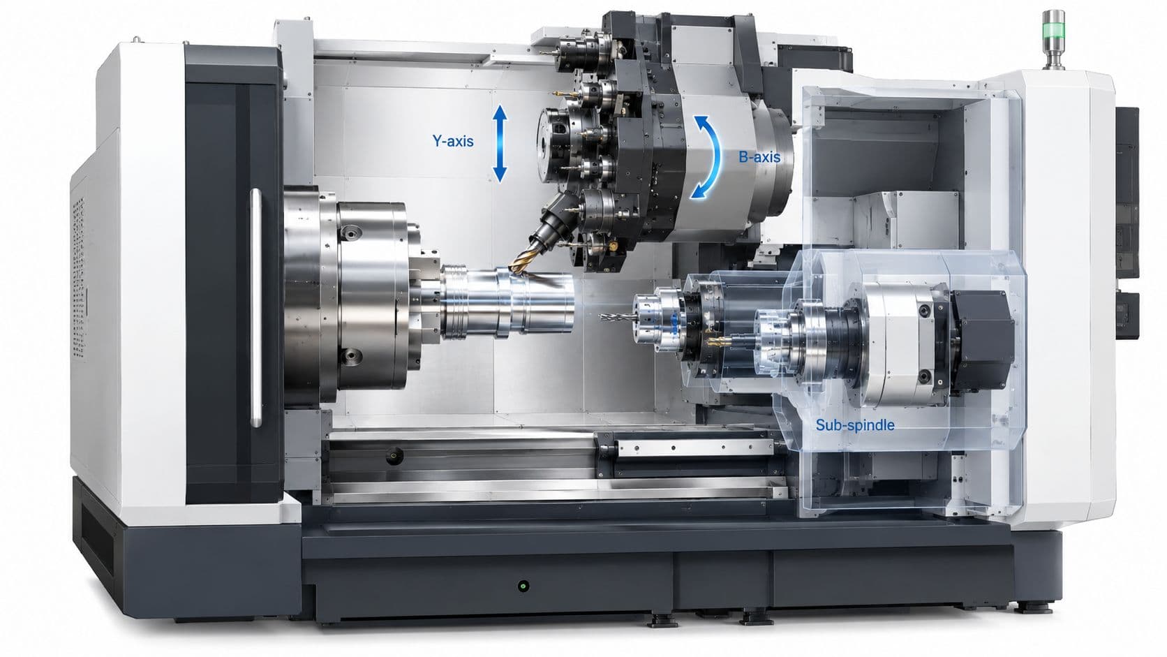
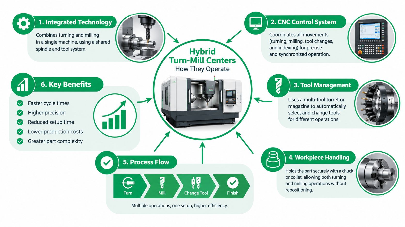
A modern turn-mill center coordinates several systems that would traditionally be distributed across a lathe and a milling machine. The main spindle holds and rotates the workpiece for turning. Live tooling rotates cutting tools mounted in a turret or tool station, allowing the machine to mill, drill, tap, and interpolate features while the workpiece is indexed or held stationary.
The exact layout varies by machine builder, but the operating logic is consistent. The control must synchronize spindle position, tool rotation, linear axes, rotary axes, and sometimes a second spindle. Engineers should understand that capability on the machine specification sheet doesn't automatically mean every feature is practical. Reach, clearance, workholding, tool length, and chip evacuation still determine what the process can do reliably.
The main spindle establishes the primary reference
The first operation normally uses the main spindle to rotate the raw stock. Turning tools remove material from the outside diameter, face the end, cut grooves, or produce threads. The machine's chuck, collet, or bar-feeding arrangement determines how much of the part can be supported and how much deflection the process may introduce.
Once the turning work is complete, the spindle can orient the part to a known angular position. Live tooling then approaches the workpiece for cross-holes, flats, keyways, and other features that don't require continuous workpiece rotation.
A Y-axis adds radial movement relative to the spindle centerline. That matters when a tool must move above or below the centerline to mill a wider feature, locate an off-center hole, or generate a contour without relying only on spindle interpolation. Without adequate Y-axis travel, a design may technically fit the machine but require awkward toolpaths or a secondary operation.
The sub-spindle supports transfer and backworking
A sub-spindle can grip the part after the main spindle completes its operations. The machine then transfers the workpiece under CNC control, allowing the original holding area to be machined. This is useful for parts that need a finished second face, rear bore, end thread, or other backworking feature.
The transfer is still a process step that needs verification. Jaw pressure, pickup position, part stick-out, and the cleanliness of the gripping surface affect repeatability. A sub-spindle doesn't remove the need for sound workholding design. It makes the transfer controlled and integrated rather than dependent on a separate fixture and manual relocation.
The B-axis changes tool approach
The B-axis tilts the milling spindle or tool carrier, depending on the machine architecture. It can orient the cutter toward angled faces and compound surfaces, which expands access beyond the fixed radial and axial directions of basic live tooling.
That flexibility creates new constraints. A tilted tool may collide with the chuck, sub-spindle, turret, tailstock, or a nearby feature before the cutter reaches the intended surface. Engineers should provide the supplier with the complete assembly context when necessary, not only the nominal part model.
For broader background on machine operations and CNC process planning, see this guide to the CNC machining process. The key design question remains simple: can the required tool approach be achieved with a rigid tool, sufficient clearance, and a manageable chip path?
Technical Capabilities and Precision Limits
Turn-mill machining can produce accurate complex parts, but it doesn't create a universal tolerance shortcut. The achievable result depends on machine condition, workholding stiffness, tool overhang, material behavior, thermal control, probing, tool wear, and the way the program distributes cutting forces.
The process also has a distinctive motion problem. In turn-milling, the cutting action is intermittent because the rotating tool engages a rotating workpiece in a changing relationship. A peer-reviewed study reports that circularity error cannot be eliminated entirely under these conditions, but increasing the tool-to-workpiece spindle-speed ratio can reduce it. The same study notes that a low workpiece rotational speed reduces centrifugal force, which can improve accuracy on large parts, as described in this peer-reviewed turn-milling study.
Process geometry controls the finish
Surface finish is not a fixed property of the machine. Tool engagement, cutter orientation, insert geometry, radial depth, feed, spindle-speed relationship, and the stiffness of the part all influence the result. A strategy that works for a short, rigid hub may produce unacceptable marks on a long, thin shaft.
Recent comparative work reports that orthogonal turn-milling is suitable for high-precision machining at relatively high material-removal rates when the required surface roughness is below Ra 0.21 μm, provided the process window is selected correctly. That result doesn't mean every turn-mill center will deliver that finish on every material. It shows that process geometry directly affects the trade-off between surface quality and material-removal rate, as discussed in this comparative analysis of turn-milling strategies.
Specify the process, not just the result: A surface-finish callout without material, tool access, geometry, and inspection context leaves the supplier solving an undefined problem.
Axes expand access, not rigidity
The combination of X, Z, live-tool rotation, Y, and sometimes B-axis movement allows a single machine to reach features that would otherwise require a mill. That flexibility is valuable for off-axis holes, angled slots, compound contours, and multi-face features. It also increases the number of ways the tool can approach the workpiece, which increases programming and collision-verification demands.
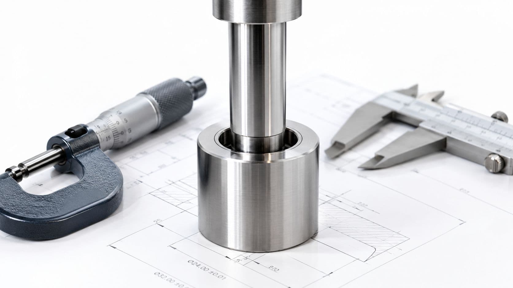
For design release, distinguish between a tolerance that controls function and a tolerance that merely reflects a preferred machining convention. Apply tight positional and form requirements to the features that establish fit, sealing, rotation, or assembly alignment. Give the manufacturer enough datum information to understand how those requirements relate to the turned axis. Guidance on tight-tolerance machining for engineered components can help teams frame those requirements before requesting a quote.
Large and slender parts need a different strategy
A low workpiece speed can help reduce centrifugal effects on large-scale parts, but the supplier still has to manage deflection and vibration. Long unsupported sections, deep bores, interrupted cuts, and thin walls can all make the nominal machine capability irrelevant.
Ask for a process review when the design includes:
- Thin walls: These can deform under chuck pressure or cutting load.
- Long stick-out: The tool and workpiece may deflect even when the programmed path is correct.
- Deep internal features: Tool access and chip evacuation can become the limiting factors.
- Interrupted turning and milling: Changing engagement can destabilize the cut.
- Multiple critical datums: The inspection plan must confirm the relationships, not only individual dimensions.
A capable supplier should respond with a proposed workholding method, tool approach, inspection strategy, and realistic tolerance discussion. Treat an unexplained promise of universal precision as a warning sign.
Turn-Mill vs Separate Lathe and Mill Workflows
The economic comparison starts with the part, not the machine. A conventional lathe plus mill may have lower programming complexity and lower hourly cost for straightforward work. A turn-mill center becomes financially persuasive when it removes enough setups, handling, inspection, and error exposure to offset its more demanding programming and process validation.
Current market estimates place the global CNC turn mill centers market at $3.8 billion in 2025 and project $6.2 billion by 2034, implying a 5.8% CAGR, according to this market estimate for CNC turn-mill centers. A separate industry estimate places the broader turning machine and equipment market at $13.40 billion in 2025, $14.20 billion in 2026, and $19 billion by 2031, with a projected 6% CAGR from 2026 to 2031. These figures describe equipment markets, not the savings on an individual part, so they shouldn't be used as a substitute for a routing-level cost model.
The break-even question
Build the comparison around the actual manufacturing route:
- Count every planned setup, not only the major machine operations.
- Include loading, unloading, deburring, cleaning, in-process inspection, and queue time.
- Identify which dimensions depend on transferring a datum from one fixture to another.
- Add programming, simulation, prove-out, and tool-management effort.
- Price the consequence of a failed first article or a late design change.
Turn-mill machining usually has the strongest case when a part needs turning plus off-axis milling, backworking, or angularly related features. It has a weaker case when the milling content is minor, the part is easy to fixture repeatedly, or the turning operation dominates the total work.
Process selection matrix
| Workflow Characteristic | Turn-Mill Center (Single Setup) | Separate Lathe and Mill (Multi-Setup) |
|---|---|---|
| Primary geometry | Strong fit for rotational parts with integrated secondary features | Efficient for mostly cylindrical parts |
| Setup count | Can consolidate turning, milling, drilling, and backworking | Requires transfers between machine types |
| Datum control | One machine reference can govern related features | Each transfer introduces another alignment task |
| Programming | More complex, especially with Y-axis, B-axis, and sub-spindle motion | Simpler programs for isolated turning and milling |
| Tool access | Flexible, but limited by machine envelope and interference | Each machine can be selected for its specific access |
| Workholding | Integrated chuck, collet, or sub-spindle strategy | Separate fixtures may be easier to optimize |
| Inspection risk | Fewer handling events, but integrated process verification is essential | More opportunities for transfer and setup variation |
| Best economic fit | Complex, high-mix, low-volume rotational parts | Simple parts or work that naturally separates into operations |
The market context also supports the direction of travel. One industry summary projects mill-turn centers to grow at a 14.9% CAGR from 2026 to 2033, compared with 4.5% for the broader milling machine market, as reported in this industry comparison of turn-mill adoption. That projection indicates demand for integrated machining, but it doesn't prove that a turn-mill center is cheaper for your component.
Procurement test: Ask the supplier to quote two routings, one integrated and one separated, with setup, programming, inspection, and expected scrap risk shown as separate cost drivers.
Hidden Costs and Programming Risks
A turn-mill center can reduce physical handling while increasing digital complexity. The machine may complete more operations without unclamping, but the programmer now has to manage spindle synchronization, tool orientation, work offsets, sub-spindle transfer, safe positions, turret sequencing, and machine-specific kinematics.
That complexity is where many promised savings disappear. A generic CAM simulation may show a clean cutter path while failing to model the actual turret, chuck, tailstock, sub-spindle, driven-tool orientation, or control behavior. The resulting program can be technically valid in the CAM environment and unsafe on the machine.
Postprocessors are part of the process
A postprocessor translates CAM intent into the syntax and motion logic required by a specific controller and machine configuration. Mill-turn posts often need careful tuning for spindle synchronization, polar interpolation, B-axis positioning, tool-center-point behavior, and transfer macros.
Don't treat the postprocessor as a file that gets installed once and forgotten. Validate it against representative programs and machine motion. A change to the machine configuration, tooling arrangement, or control option can make an old post unsafe or inaccurate.
Software can help. Recent industry coverage describes the use of AI, machine learning, digital twins, and improved postprocessors to reduce cycle-time and crash risks in turn-mill workflows, while also emphasizing that the machines are attractive for automation and complete-in-one machining. These tools support a disciplined process, but they don't replace a programmer who understands the machine's physical limits.
Verification must model the machine
Collision checking should include more than the cutter and the stock. Verify the complete machine envelope, including:
- Toolholders and driven-tool units
- Turret body and adjacent stations
- Main and sub-spindle chucks
- Tailstock, steady rests, and fixtures
- B-axis rotation and cable or hose clearance
- Transfer motions and safe retract positions
A prove-out plan should start conservatively. Use reduced rapid overrides, verify the first tool changes, confirm spindle orientation, and inspect the transfer sequence before allowing unattended production.
Chips can decide whether automation works
Turn-milling can generate shorter chips, which may improve swarf handling. That benefit is conditional. The programmer and process engineer still need to manage chip direction, coolant delivery, tool access, and the accumulation of chips around the sub-spindle or deep features, as discussed in this technical article on applying turn-milling.
A process that produces acceptable parts during attended production may still fail during an unattended run if chips wrap around a tool, block coolant, scratch a finished surface, or interfere with a transfer. Evaluate chip control as a reliability requirement, not a housekeeping detail.
DFM Guidelines for Multitasking Machining
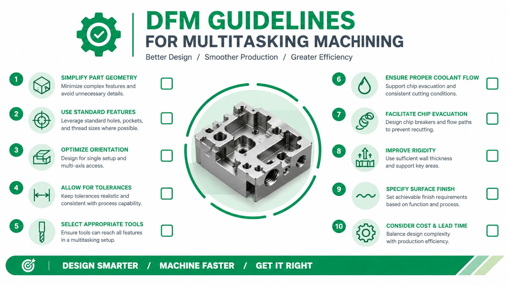
Designing for a turn-mill center means designing around coordinated access. The CAD model may show that a hole or pocket exists, but the manufacturing question is whether a rigid tool can reach it at a useful angle while clearing the spindle, chuck, neighboring walls, and other machine components.
The best DFM reviews happen before the drawing is frozen. Give the supplier the model, drawing, material, critical datums, finish requirements, and intended function. A programmer can then distinguish between a feature that is straightforward in the machine and one that technically fits but creates an unstable or expensive process.
Place features where the machine can reach them
Off-axis holes are a natural application for live tooling, but their position still matters. Keep the hole axis accessible from a stable tool direction when possible. Avoid surrounding the feature with tall walls that force excessive tool extension or require a complicated B-axis approach.
For angular hole patterns, define the relationship to a clear turned datum. If the part will be indexed from the main spindle, make the angular reference unambiguous in the drawing. A vague clocking requirement can create inspection disagreements even when the machining program is correct.
Protect rigidity and workholding
Part proportions influence both cutting stability and clamping. Long slender sections may need a tailstock, steady rest, or a carefully staged sequence. Thin flanges can distort under chuck pressure, while deep cavities can restrict tool access and trap chips.
Useful design checks include:
- Wall thickness: Avoid thin sections that flex under cutting force unless the function requires them and the supplier can support them.
- Corner radii: Use radii compatible with available cutters instead of forcing sharp internal corners.
- Tool clearance: Leave room for the holder, not only the tool tip.
- Bore depth: Match depth to boring-bar stiffness and chip evacuation.
- Part transfer: Provide a reliable gripping surface for sub-spindle pickup when both ends need machining.
Design review question: If the supplier needs a custom fixture or an unusually long tool to reach one feature, ask whether moving that feature or changing its datum would preserve function at lower process risk.
Separate functional precision from visual preference
Not every edge needs a tight positional tolerance or a premium finish. Over-specification can force slower tools, extra finishing operations, or a secondary process that defeats the reason for choosing a mill-turn route.
Identify the surfaces that control assembly, sealing, rotation, alignment, or wear. Then define inspection methods for those surfaces and their relationships. For nonfunctional edges, a practical chamfer or standard edge break usually gives the manufacturer more freedom to control burrs and cycle stability.
Material matters as well. Tough alloys, gummy plastics, abrasive materials, and heat-sensitive metals each change tool selection and chip behavior. A supplier should review the material together with the geometry rather than approving the model in isolation.
Sourcing Prototypes and Low-Volume Production
For prototypes and low-volume production, the right supplier is the one that can connect design intent to a controlled process. Machine count alone doesn't prove that a shop can run your part. Ask how the team handles mill-turn programming, machine simulation, workholding, first-article inspection, material traceability, and design revisions.
Start with a capability screen:
- Machine configuration: Confirm the available Y-axis, B-axis, live tooling, sub-spindle, bar capacity, and working envelope.
- Programming ownership: Identify who builds and validates the postprocessor and who approves the final NC program.
- Inspection method: Ask how the supplier will establish the turned axis and verify off-axis features against it.
- Process evidence: Request a sample process plan or a technical review of a comparable geometry, subject to confidentiality.
- Finishing control: Determine whether deburring, surface treatment, cleaning, and inspection remain coordinated after machining.
A prototype supplier should also be willing to challenge the drawing. If an off-axis hole requires an awkward tool approach, the team should explain the constraint and propose a functional alternative. If the part needs turning, milling, and finishing from separate vendors, ask who owns the dimensional relationship after each handoff.
Match the workflow to the part family
A simple rotational prototype may be better served by conventional CNC turning. A shaft with milled flats and cross-holes may benefit from live-tool turning. A complex housing may require a turn-mill center for the primary features and a separate milling or finishing process for surfaces the hybrid machine can't access efficiently.
For low-volume work, don't judge the quote only by the machine rate. Compare the total path from CAD review through inspection and finished delivery. A slightly more complex machine process can be sensible when it reduces fixture development, protects a critical datum, and avoids repeated coordination between suppliers. It can also be the wrong choice when programming and prove-out effort dominate the job.
FIRMFG provides CNC turning and mill-turn machining for parts that combine turned geometry with milled flats, grooves, and holes, along with related prototyping, inspection, and finishing workflows. That type of consolidated capability is useful when the project needs early DFM feedback and a controlled path from prototype machining into low-volume production.
Before releasing the purchase order, send the supplier the part model, drawing, material specification, annual or project volume, critical features, finish requirements, and target inspection records. Request a written response that identifies the proposed setup, machine configuration, tooling assumptions, inspection plan, and any geometry that may require a secondary operation.
If your part combines rotational geometry with off-axis features, send the CAD model and drawing to FIRMFG for a practical DFM and process review. Ask the team to compare a mill-turn route with separate lathe and milling setups, then use the resulting setup, inspection, and risk analysis to choose the process that fits your prototype or low-volume program.