CNC Turning Definition, Process, and Practical Use Cases
CNC turning is a subtractive process in which a rotating workpiece is shaped by a computer-controlled single-point cutting tool. It produces cylindrical parts such as shafts, sleeves, threads, pins, and bushings, with high-end applications reporting tolerances as tight as ±0.005 mm.
You may be looking at a prototype drawing with a shaft, a bushing, a cross-hole, and a flange, and wondering why one shop recommends turning while another recommends milling. The answer starts with the part's geometry, not the machine's marketing label. Turning creates rotational features efficiently, while milling handles features that sit away from the centerline. Modern turning centers can combine both approaches, often changing the most useful question from “turning or milling?” to “how many setups will this part need?”
Table of Contents
Lathes, Turning Centers, and Live Tooling Explained- The basic two-axis lathe
CNC Turning vs Milling and How They Work Together
Materials That Turn Well and the Ones That Cause Trouble
Tolerances, Surface Finish, and What Spec Numbers Really Mean- Reading surface finish values
Design for Turning and Five Tips That Cut Cost and Lead Time
How FIRMFG Runs Turning for Prototyping and Low Volume
Where CNC Turning Is Heading in Connected Manufacturing- What connected turning changes for designers
What CNC Turning Actually Means
Suppose you upload a 3D model of a shaft-and-bushing assembly. A machinist examines the long diameters, shoulders, bores, threads, and end faces, then identifies the flange pockets or cross-holes that may need milling. That first process decision affects the machine, tooling, inspection plan, material usage, and the tolerances your shop can hold economically.
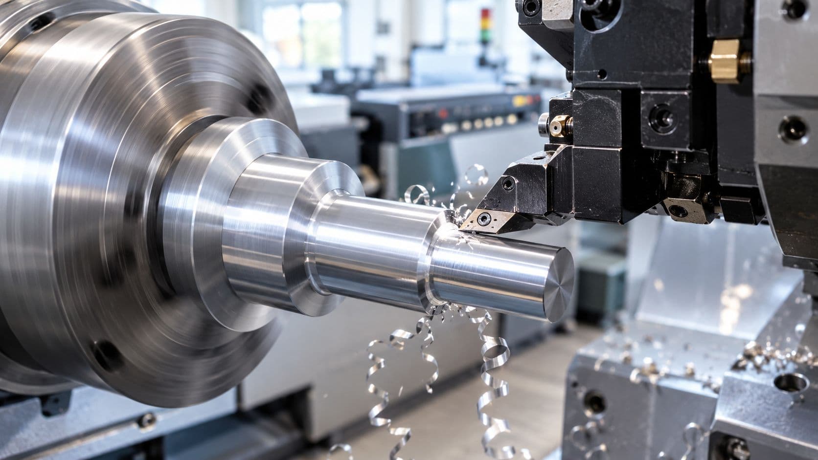
CNC turning is a subtractive machining process. The workpiece rotates in the spindle while a single-point cutting tool removes material under computer control. The tool follows programmed paths to create outside diameters, inside diameters, faces, tapers, grooves, threads, and profiles that share the part's axis of rotation. This is the modern computer-controlled development of the lathe, a manufacturing concept with roots extending back to ancient Egypt. Numerical control work by John T. Parsons and MIT in the late 1940s laid important foundations, while microprocessors made CNC technology practical in 1976 and afterward, as described in this history of CNC turning.

The three motions that define the process
A basic CNC lathe coordinates three machine actions:
- Spindle rotation: The chuck or collet spins the bar, tube, or billet at a controlled speed. The rotating workpiece supplies the cutting speed.
- Tool feed: The cutting tool moves along the Z axis, parallel to the spindle, and along the X axis, toward or away from the centerline. This division creates the familiar turning geometry described in this technical explanation of CNC turning motion.
- Turret indexing: The turret selects the appropriate tool, such as an external turning insert, drill, boring bar, grooving tool, or threading tool.
Parts that map naturally to this process include shafts, pins, threaded fasteners, bushings, nozzles, valve bodies, knurled grips, bone screws, and short-run production components. The process is also widely used because it removes chips directly from rotational stock and can produce cylindrical geometry efficiently, as outlined by Mecanumeric's lathe technology overview.
Practical rule: If most important features share one centerline, start the quote conversation with turning. If the drawing depends on pockets, flats, or off-center features, ask how those features will be made without adding unnecessary setups.
For a deeper look at how a prototype shop applies the process, see FIRMFG's CNC turning services. Defining the process before assigning tolerances prevents a common design mistake, specifying milling-style geometry on a part that should have been planned around a turning setup.
Lathes, Turning Centers, and Live Tooling Explained
Machine capability grows in layers. A basic two-axis CNC lathe may be all a simple spacer needs, while a complex connector or sensor housing may benefit from a turning center with live tooling, a Y axis, and a sub-spindle.
The basic two-axis lathe
A chuck or collet holds the raw bar or billet. The spindle rotates it, the Z axis moves the tool along the part length, and the X axis controls the cutting diameter. This configuration handles outside turning, facing, boring, grooving, and threading.
The machine's rigidity matters during roughing. A rigid setup lets the tool remove material without excessive vibration, while a weak clamping arrangement can produce chatter, poor finish, and dimensional drift. For a shaft with turned diameters and a simple bore, adding more axes may increase programming and setup complexity without adding useful capability.
The turning center
A CNC turning center adds functions that reduce handling. Depending on its configuration, it may include a driven turret, C-axis spindle control, Y-axis motion, a sub-spindle, and automated part transfer.
The C axis controls spindle orientation, either by indexing the workpiece to a position or by coordinating spindle rotation with tool motion. That lets the machine locate a cross-hole, drill a bolt pattern, or mill a flat at a defined angular position.
Live tooling and bar feeding
Live tooling places powered rotary tools in the turret. While the main spindle holds the workpiece, a driven drill or milling cutter can create cross-holes, slots, flats, or end features. A Y axis moves the tool away from the centerline, making off-center features accessible without sending the part to a separate mill.
Bar feeders extend the automation layer for shaft-like parts. A pusher or magazine-style system presents additional stock to the spindle, allowing the machine to continue through a run with less manual loading. That can support unattended production, but the value depends on part geometry, tool life, chip control, inspection, and the stability of the process.
Each added capability expands the geometry that can be completed in one setup. For prototype work, that matters because one setup can remove a fixture change, a handoff, and a possible alignment error.
CNC Turning vs Milling and How They Work Together
Turning and milling differ mainly in what rotates. In turning, the workpiece rotates against a stationary or linearly moving single-point tool. In milling, the cutting tool rotates while the workpiece remains fixed or moves through several controlled axes.
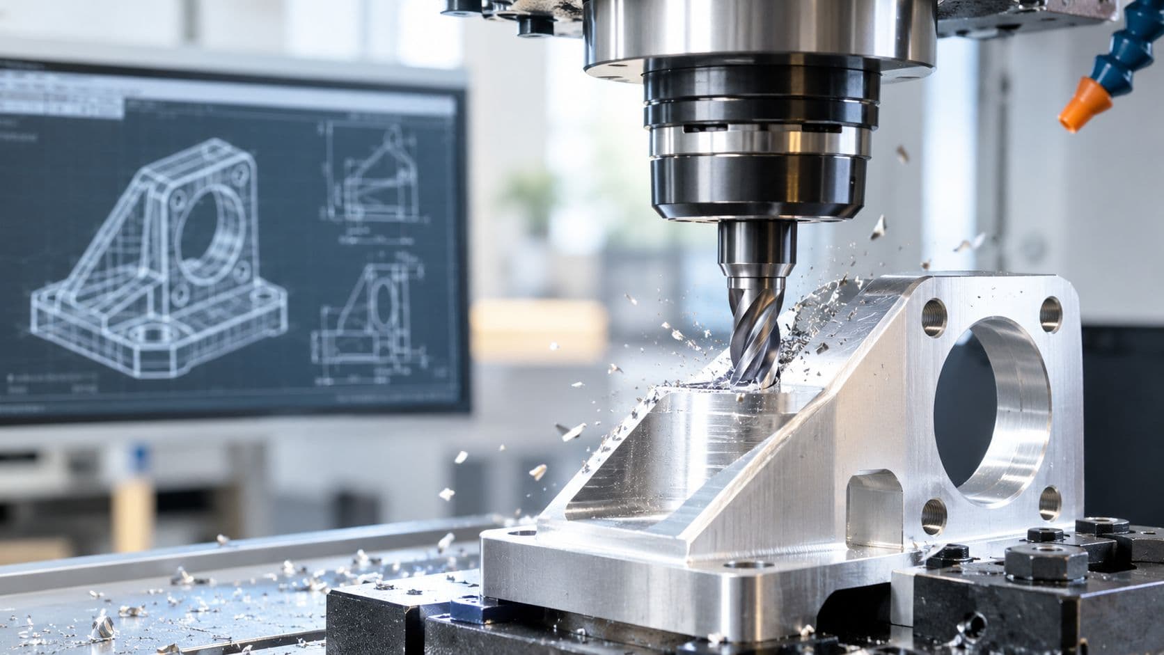
Consider a stub shaft with an outside diameter, a faced end, chamfers, two milled flats, and a cross-drilled hole. A two-axis lathe can produce the outside diameter, face, and chamfers in one setup. The flats and cross-hole require either a second milling operation or a turning center equipped with C-axis control, live tooling, and suitable Y-axis access.
A hex drive profile is a useful boundary case. If the hex is the dominant geometry, milling may be the more direct choice because the tool can generate the prismatic faces without forcing a turning setup to imitate a milling operation. If the part is mostly cylindrical and has one small flat and one cross-hole, a mill-turn setup may reduce handling.
| Factor | CNC Turning | CNC Milling |
|---|---|---|
| Primary rotation | The workpiece rotates | The cutting tool rotates |
| Natural geometry | Shafts, pins, bores, tapers, threads, grooves | Pockets, slots, flats, contours, and prismatic features |
| Basic tool | Single-point turning tool | Multi-edge rotating cutter |
| Main setup question | Can the features be reached from the spindle axis? | Can the workpiece be held and oriented for each feature? |
| Strongest advantage | Efficient axisymmetric machining | Flexible access to non-rotational geometry |
| Common hybrid use | Turn the body, then mill cross-features with live tooling | Mill prismatic features after turning when the part needs a separate operation |
Modern turning centers blur the boundary. A machine with live tooling and a Y axis can complete 70 to 80 percent of common turned-and-milled parts in one setup, according to the CNC turning process overview from Hubs. The exact share depends on the part, tooling, machine envelope, and inspection requirements, so it shouldn't be treated as a universal rule.
The practical decision is therefore not simply turning versus milling. Ask whether the chosen process can complete the critical features in one setup, and whether that reduction in handling outweighs the programming and machine complexity.
Materials That Turn Well and the Ones That Cause Trouble
Material selection changes the cutting behavior long before the first chip reaches the conveyor. A material that is easy to turn in a thick-wall bushing may behave poorly in a thin-wall sleeve, and the same alloy can produce different results when the tool geometry, coolant, or chip breaker changes.
| Material Family | Examples | Machinability relative | Key Turning Implication |
|---|---|---|---|
| Aluminum alloys | 6061, 7075 | Generally favorable | Supports efficient prototype work, but sharp tools and clean chip evacuation help protect surface finish |
| Mild and stainless steels | Low-carbon steel, stainless grades | Variable | Chip control, work hardening, rigidity, and coolant strategy strongly affect tool life |
| Copper and brass | Brass, copper | Often favorable, depending on grade | Continuous chips and surface smearing can require suitable tool geometry and cutting conditions |
| High-temperature alloys | Titanium, Inconel | Challenging | Heat management, rigid tooling, reduced cutting conditions, and effective coolant become important |
| Engineering plastics | Delrin, PEEK, UHMW | Generally machinable | Clamping can cause deflection, and heat buildup can distort thin sections |
Aluminum, including 6061 and 7075, is a common prototyping baseline because it cuts cleanly with suitable sharp tooling. Designers still need to account for burrs, thin walls, and chip evacuation around deep bores.
Steel and stainless steel demand more attention to chip control. Some stainless materials work harden when the tool rubs instead of cuts, so a timid feed or unstable setup can make the next pass harder. A machinist may choose a chip breaker, coolant approach, and roughing strategy that keeps the insert engaged decisively.
Titanium and Inconel are less forgiving. They retain heat near the cutting zone and place greater demands on tool rigidity and coolant delivery. That doesn't make them unsuitable for turning, but it makes the process plan more important than just selecting a stronger insert.
Engineering plastics bring a different problem. Delrin, PEEK, and UHMW can produce useful low-friction prototype components, yet a thin sleeve can deflect under chuck pressure or expand from cutting heat. Magnesium deserves special process review because tool-workpiece reactivity and chip ignition risk can affect the machining plan. Long-chipping stainless and thin-wall geometries also need deliberate chip and heat management.
A material is not “easy” or “difficult” in isolation. Judge it against the part's wall thickness, unsupported length, bore depth, clamping method, and required finish.
Tolerances, Surface Finish, and What Spec Numbers Really Mean
A tolerance on a drawing is a manufacturing instruction, not a declaration of what the machine can achieve under every condition. A shop must control workholding, tool wear, temperature, measurement method, and the order of roughing and finishing operations.
For practical CNC turning, industry guidance reports a default tolerance of about ±0.005 in, or ±0.13 mm, a routine diameter precision around ±0.001 in, or ±0.025 mm, and a tighter value of ±0.0005 in, or ±0.013 mm when the process includes a dedicated finish pass and stable temperature, as detailed in this CNC turning tolerance and finish guide. High-end applications may report tolerances as tight as ±0.005 mm, but that figure belongs to a controlled application, not a blanket promise for every turned feature.
Reading surface finish values
Surface roughness uses Ra, the arithmetic average roughness. A typical as-turned surface may be about 125 µin Ra, or 3.2 µm, while a finishing operation can improve it to roughly 32 µin Ra, or 0.8 µm. Values below 8 µin Ra generally require a secondary process such as grinding or roller burnishing.
That distinction matters when a designer specifies a bearing seat, sealing bore, or cosmetic face. A turned prototype may be dimensionally correct but still need a finishing operation if the surface must support a seal, sliding motion, or controlled optical interface. Roughness also doesn't replace geometric control. A shaft can meet its diameter tolerance while still showing unwanted taper, out-of-roundness, or misalignment between features.

Use tighter tolerances only where function requires them. A bearing seat may need careful diameter and cylindricity control, while a nonfunctional relief diameter may not. For a broader explanation of roughness parameters, see Ra versus Rz surface finish.
Inspection reality: A tight number on a drawing creates work for the machine, the operator, and the quality team. Specify the functional requirement, then let the shop help choose the most economical process that satisfies it.
Design for Turning and Five Tips That Cut Cost and Lead Time
Good turning design starts before toolpaths are generated. The drawing should help the machinist hold the part securely, reach every feature with standard tooling, and inspect the dimensions without unnecessary rework.
- Keep the rotation axis consistent. Put the primary diameters, bores, shoulders, and grooves on one centerline whenever the function allows it. The shop can then complete more features without re-chucking the part, which reduces setup handling and alignment risk.
- Choose practical round stock. Designing around commonly available bar diameters can avoid specialty material sourcing. This is especially useful for one-off prototypes, where buying an unusual stock size can dominate the schedule even though the machining itself is straightforward.
- Use generous internal radii. A sharp internal corner is difficult for a standard turning insert to reach because the insert has its own nose radius. The largest functional radius your assembly can accept gives the tool room to cut and reduces the need for a custom-ground tool.
- Reserve tight tolerances for functional surfaces. A bearing seat, press-fit bore, or locating diameter may need close control. A clearance diameter or cosmetic step usually doesn't need the same specification, and leaving it at a standard tolerance can reduce finishing and inspection effort.
- Standardize threads, grooves, and undercuts. Common thread pitches and standard grooving widths let the shop use stocked inserts and proven programs. A nonstandard groove may require special tooling, extra setup work, or a separate verification step.
Thin walls deserve special attention even when the diameter appears easy to cut. Clamping pressure can distort a sleeve, while a long unsupported section can chatter during finishing. Add support where possible, shorten the unsupported length, or ask whether a steady rest, soft jaws, or a different sequence would protect the geometry.
The practical DFM principles in this design for manufacturability engineering guide apply especially well to turned parts because the process rewards aligned features and standard tooling.
How FIRMFG Runs Turning for Prototyping and Low Volume
A prototyping-focused workflow starts with the model and drawing, not with a machine assignment. Engineers review the rotational features, material, tolerances, surface finish, stock form, and any cross-features that may require live tooling or a secondary milling operation.
FIRMFG provides DFM feedback within 12 hours as part of its stated prototyping workflow. For a 303 stainless shaft with ±0.001 in tolerances, the review would focus on tool access, workholding, finishing passes, inspection points, and whether the tolerance applies to a functional diameter or to a less critical feature.
A different example is a Delrin bushing turned from bar stock with a live-tooled cross-hole. The process plan must protect the plastic from clamping distortion, maintain the bore during finishing, and orient the cross-hole accurately relative to the turned features. A turning center can reduce handling when its live tooling and Y-axis access match the design.
FIRMFG supports single-piece through 50-piece runs on Swiss-style and multi-axis turning centers, according to the supplied capability brief. Inspection can include calipers, micrometers, and CMM measurement, with the inspection method selected according to the feature and tolerance.
The workflow also extends beyond cutting. Material sourcing covers common metals and plastics, while secondary services include anodizing, passivation, and assembly. That lets a prototype team request a machined part that is closer to bench-test condition instead of coordinating separate finishing and assembly handoffs.
Where CNC Turning Is Heading in Connected Manufacturing
The definition of turning is stable, but the surrounding workflow is changing. A spindle still rotates the workpiece, and a tool still removes material, yet newer production environments connect quoting, programming, machine monitoring, inspection, and scheduling instead of treating each step as an isolated job.
Current CNC manufacturing trend coverage identifies AI-powered automation, predictive maintenance, digital thread integration, localized manufacturing, and hybrid additive and subtractive production as important themes for 2025, as discussed in this 2025 CNC machining trends forecast. These developments don't replace process knowledge. They give engineers and shops more information about how a process behaves before and during production.
What connected turning changes for designers
A connected turning center can send operating data into manufacturing execution systems, helping production teams relate machine status to a specific order or process step. Digital twins can support simulation of spindle loads, tool access, and chip evacuation before material is loaded. Tool-wear monitoring can alert the team when a finishing insert is drifting toward an unacceptable condition.
For a product designer, the benefit appears as fewer surprises. A quote can account for material and feature access earlier, DFM feedback can identify an impossible setup before programming begins, and inspection data can reveal whether a drawing needs a functional tolerance rather than a blanket tight tolerance.
The same logic supports the transition from a one-off prototype to a low-volume production run. A shop that preserves the CAD model, process plan, inspection points, and revision history has fewer opportunities to lose design intent between iterations. Automation also becomes more useful when the part family is stable enough to justify repeatable loading, tool monitoring, and inspection routines.
The strongest manufacturing workflows will combine digital quoting, automated inspection, process traceability, and the right turning capacity for the part. The machine doesn't become valuable because it has the highest possible axis count. It becomes valuable when its capabilities remove a setup, protect a tolerance, shorten a handoff, or make the next build easier to repeat.
FIRMFG offers CNC turning and multi-axis machining for metal and plastic prototypes, with DFM support, inspection, finishing, and low-volume production workflows. Share your part model and drawing with FIRMFG to review whether turning, milling, or a combined setup fits your geometry and functional requirements.