Ra vs Rz Surface Finish: Engineering Comparison
You're staring at a drawing review, and the supplier just asked the question nobody wants to answer late in the project, should this surface be Ra or Rz? The part looks fine on paper, the machining quote is already moving, and yet one wrong callout can turn into a rejection at incoming inspection, or worse, a part that passes the gauge and fails in the field. That's where ra vs rz surface finish stops being a textbook comparison and starts being a sourcing problem.
| Parameter | What it measures | Best at catching | Typical weakness | Why designers use it |
|---|---|---|---|---|
| Ra | Average absolute profile deviation | General texture consistency | Can hide isolated peaks or valleys | Stable, easy to measure |
| Rz | Average of five peak-to-valley heights | Deep scratches, burrs, and other extremes | More sensitive to local outliers | Better when defects affect function |
The trap is simple. A part can look acceptable by Ra and still carry a valley or scratch that matters for sealing, fatigue, or coating. That's why the standard you cite matters as much as the number itself, and why the same drawing callout can behave differently across plants, suppliers, and inspection rooms.
Table of Contents
- Ra and Rz Surface Finish Defined
What Ra means
What Rz means
Why the standard matters
Quick comparison
How Ra and Rz Measurements Work- What the instrument actually does
Ra versus Rz Numerical Relationship and Conversion Limits- The rule of thumb and why it exists
Surface Finish Implications for CNC Machining and Finishing- What the instrument does
When to Specify Ra and When to Specify Rz- Choose Ra when the goal is general surface control
- Choose Rz when the risk lives in the extremes
- Use both when the feature is critical
- A practical selection rule
Common Pitfalls and When One Metric Beats the Other- The Ra-only trap
Specifying Surface Finish for Your Next CNC Project- Use this checklist on the drawing
Ra and Rz Surface Finish Defined
A drawing that says “surface finish acceptable” sounds clear until the part reaches the floor. One supplier reads it as cosmetic only, another treats it as a sealing requirement, and a third checks with a different standard and gets a different result. The part may look fine and still fail in service because the risk was never defined.

What Ra means
Ra is the arithmetic mean of absolute profile deviations from the mean line. The instrument traces the roughness profile, measures each deviation from that line as a positive value, and averages them across the evaluation length. In practice, that makes Ra a good general-purpose indicator for process control, because it is stable, easy to inspect, and widely recognized on drawings. The formal definition appears in ASME B46.1 and ISO 4287, which is why Ra is often the default callout in machine shops. Astro Pak's Ra definition guide
Ra is useful, but it can hide trouble. A surface with one deep scratch or a few sharp peaks can still show a respectable Ra value if the rest of the trace is fairly even. That is the trade-off designers need to keep in mind, especially on parts where a single defect can matter more than the average texture.
What Rz means
Rz measures a different part of the story. Under the ISO-style definition used in many shop conversations, it looks at peak-to-valley behavior across sampling lengths and averages the roughness heights, so it reacts more strongly to isolated defects than Ra. That makes Rz a better fit for sealing faces, fatigue-sensitive parts, and surfaces where one burr, ridge, or scratch can create a problem even if the average finish looks acceptable.
Practical rule: if a part fails because of a single bad spot, Ra alone can be too forgiving.
Why the standard matters
Drawings get misread across global supply chains. Under ISO 4287, Rz was defined as mean roughness depth averaged across sampling lengths, while ISO 21920-2:2021 defines Rz as the maximum peak-to-valley height over the evaluation length. The same symbol can therefore point to different numbers unless the governing standard is stated on the print. That is a real source of disagreement when one supplier follows a newer interpretation and another is still working from legacy practice. Olympus Machining on surface finish requirements
Quick comparison
| Item | Ra | Rz |
|---|---|---|
| Core definition | Arithmetic average roughness | Peak-to-valley depth across sampled lengths |
| What it smooths out | Small local variation | It exposes local extremes more directly |
| Best use | General texture control | Defect-sensitive functional control |
| Inspection risk | Can miss isolated defects | Can vary more with surface pattern |

How Ra and Rz Measurements Work
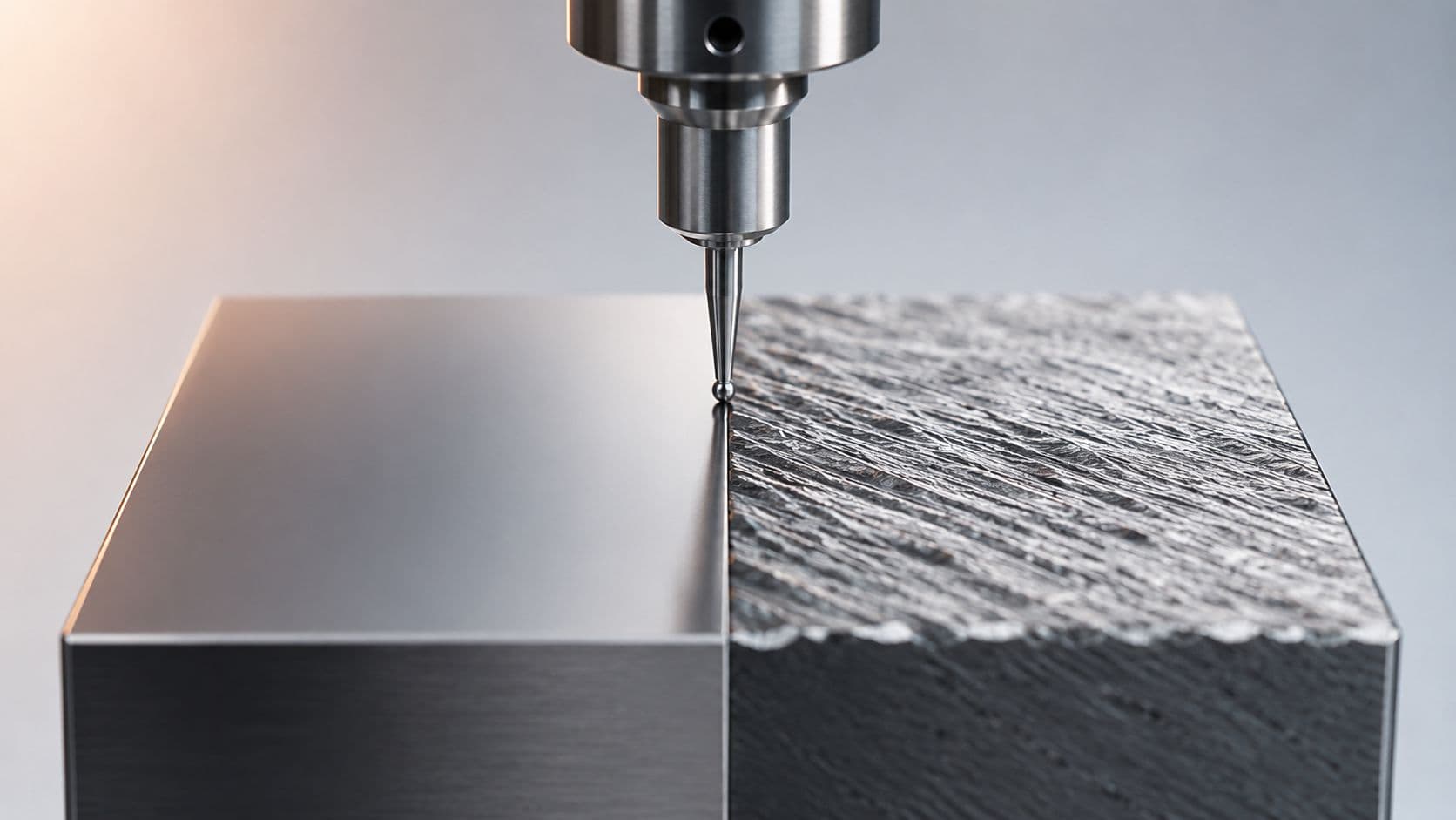
A profilometer does not judge finish the way a human eye does. It drags a diamond-tipped stylus across the surface, strips out form and waviness, then captures the fine roughness profile that remains. What comes out is not a visual impression. It is a filtered trace that the instrument turns into roughness numbers.
What the instrument actually does
The stylus moves across a defined evaluation length, and the instrument builds a mean line through that trace. Cutoff length and sampling length matter because they decide what gets counted and what gets ignored. Change those settings, and you can change the result even when the part itself has not changed. That is why roughness disputes on the shop floor often start with the setup, not the machining.
A roughness report is only as honest as the measurement setup behind it.
Ra and Rz come from the same trace, but they do not describe it the same way. Ra averages the absolute deviations across the evaluation length, so it gives a broad picture of the surface condition. Rz focuses on peak-to-valley behavior within sampled lengths, so it reacts more strongly to local peaks, burrs, and deep scratches.
Why evaluation length changes the story
ISO-style practice uses multiple sampling lengths inside the evaluation length, and the roughness value is built from those segments. A part with the same machining process can still show a different Rz if the profile is more irregular. That is one reason the same Ra value can hide a bad spot that Rz brings into view, which is why many buyers keep a surface roughness chart at hand during drawing review and supplier discussions. Surface roughness chart
The standard matters just as much as the number. Under ISO 4287, Rz was defined as mean roughness depth averaged across sampling lengths, while ISO 21920-2:2021 defines Rz as the maximum peak-to-valley height over the evaluation length. The same symbol can therefore point to different numbers unless the governing standard is stated on the print. That creates real disagreement when one supplier works from newer practice and another is still using legacy interpretation.
What to ask the shop
Use these questions during DFM or first-article review:
- Which standard is being used? Ask for the actual standard name, not just the roughness symbol.
- What cutoff and sampling length are set? The number is meaningless without the setup.
- Is the part measured across the lay? Direction matters on machined finishes.
- Are you reporting Ra, Rz, or both? A single metric does not always tell the whole story.
The inspection bench is where many roughness mistakes get exposed. If the drawing is vague and the measurement method is undocumented, you are not buying control. You are buying interpretation.
Ra versus Rz Numerical Relationship and Conversion Limits
The most dangerous habit in surface finish work is treating Ra and Rz like interchangeable versions of the same thing. People love a shortcut, so they reach for a conversion rule and move on. That works until the part is functional, the texture is irregular, or the supplier's process creates a profile that doesn't fit the rule of thumb.
The rule of thumb and why it exists
In practical machining, a widely used estimate says Rz is about 4 to 7 times Ra for turned and ground surfaces, with one common shorthand being Rz ≈ 4 × Ra. A cited example in the brief says an Ra of 1.6 µm often corresponds to an Rz around 6.4 µm or higher, depending on cut condition. That rough relationship is useful for sanity checks, but it is not a design guarantee. Metric Mech on surface finish Ra and Rz
Where the shortcut breaks
The problem is that Ra and Rz do not respond to the surface in the same way. Ra averages the whole profile, so it can blur out an isolated defect. Rz is more sensitive to local highs and lows, so it will react when the surface has a deep scratch, a burr, or a sharp valley that Ra barely notices.
One published converter cited in the brief shows how wide the spread can get. At 3.2 µm Ra, Rz can span roughly 11.5 to 34.7 µm, and at 50 µm Ra, the possible Rz range can rise to about 156.2 to 272.6 µm. Those ranges highlight that the same Ra value can hide wildly different peak-to-valley behavior depending on the texture pattern. Xometry's roughness converter discussion
The practical lesson
Don't convert just to avoid specifying the right parameter. Use conversion only as a rough conversation tool when you're comparing supplier reports or checking whether a drawing target is plausible. When the feature matters for sealing, wear, or fatigue, specify the parameter that controls the risk instead of forcing a one-size-fits-all conversion.
Surface roughness chart reference for quick checks
Use the conversion only to talk. Use the functional metric to release the part.
Surface Finish Implications for CNC Machining and Finishing
A face-milled plate, a turned shaft, and a ground sealing land can all show the same Ra on paper and behave very differently in service. The reason is simple, the surface pattern carries the process history. That matters in sourcing, because a drawing that names only one average value can miss the defect mode that controls fit, sealing, or wear.
What the instrument does
Turning and milling leave directional tool marks, so the finish depends on feed, spindle speed, tool geometry, and workpiece material. Grinding and lapping usually hold tighter control because they remove smaller amounts of material and leave finer textures. EDM often leaves a distinct surface signature that can work for some features and miss the mark for others, especially where peak shape matters more than the average roughness.
The same operation can move Ra and Rz in different directions. A finishing pass may improve the average texture while leaving a stray peak or valley in place. That is why a part can look cleaner in Ra and still miss a defect-sensitive requirement that Rz would have caught.
Secondary finishing changes the story again
Bead blasting, anodizing, painting, and polishing are not neutral overlays. They change the top surface, reshape how peaks are presented, and can hide or expose the underlying texture depending on the process. On a cosmetic surface, that may be acceptable. On a sealing surface, it can become a problem if the coating or blast media leaves texture where control was needed.
The same caution shows up in stainless work. A brushed or polished appearance does not guarantee a functionally smooth surface, and appearance-based finish language can drift away from measured roughness. For a practical reference on that gap, see this Stainless steel finish reference.
What to specify by function
- Sealing faces: control isolated valleys and scratches first, not just average smoothness.
- Bearing or sliding interfaces: match the finish to the lubrication regime and contact behavior.
- Cosmetic housings: appearance and tactile consistency may matter more than deep valley control.
- Fatigue-prone features: surface defects deserve more attention than average roughness alone.
A process that looks good on a sample coupon can still miss the load case on the finished part.
When to Specify Ra and When to Specify Rz
The right callout starts with the part's job, not with the habit of copying the last drawing. If the feature's risk is broad process variation, Ra is usually the cleaner language. If the risk is a defect hiding in the profile, Rz does a better job of forcing attention to the bad spot.

Choose Ra when the goal is general surface control
Ra works well when you want a stable, repeatable indicator of overall texture. That makes it useful for general wear and lubrication behavior, cosmetic consistency, and many non-critical machined surfaces. It's the right call when you care about how the process is trending, not whether one isolated feature is lurking in the profile.
Choose Rz when the risk lives in the extremes
Rz is the better call when a single scratch, burr, or valley can change function. That's the case on sealing surfaces, some fatigue-sensitive parts, and load-bearing areas where local geometry matters more than the average. A surface can look reasonable in Ra and still fail because one peak or valley violates the functional intent.
Use both when the feature is critical
Some parts need both numbers because they solve different problems. Ra tells you the overall texture is in family, while Rz limits the defect extremes that can cause leakage, crack initiation, or coating issues. In that situation, the dual callout isn't redundant, it's a way to close the loophole that a single metric leaves open.
A practical selection rule
- General appearance and process consistency: Ra first.
- Leak paths, scratches, or local damage risk: Rz first.
- High-consequence features: both parameters, plus the governing standard.
- If you're unsure: ask what failure mode the surface is supposed to prevent.
This is the function-first approach that prevents over-specifying the wrong thing. Designers often chase a lower number when they should be chasing the right failure mode instead.
Common Pitfalls and When One Metric Beats the Other
The biggest mistake is treating a good Ra result as proof that the part is safe. A surface can pass an average roughness check and still hide a deep valley or isolated scratch that creates a leak path or a fatigue initiation site. That is a specification failure, because the callout did not control the feature that governs performance.
The Ra-only trap
Ra works well for broad process control, but it smooths out outliers. That means it can miss the defect that matters most on a critical part. If the feature is a gland, a seat, or a surface that has to survive cyclic stress, Ra by itself is often too forgiving.
A part fails when one local defect crosses the line. The average looked fine.
The standards confusion trap
The other common failure is calling out Rz without naming the governing standard. As noted earlier, ISO 4287 and ISO 21920-2:2021 define Rz differently, so the same symbol can be read in two ways depending on who is looking at the drawing. In a global supply chain, that is how a part gets measured one way at the shop and another way at incoming inspection. Olympus Machining on Rz standard differences
How to prevent the dispute
A simple prevention stack works better than arguing after the fact:
- State the standard explicitly: put the governing roughness standard on the drawing.
- Tie the metric to function: say why the surface matters, not just what number it needs.
- Use dual callouts on critical features: one number rarely closes every loophole.
- Review measurement method early: align on stylus, cutoff, and sampling length before production starts.
For a practical drafting example, the guidance in this surface texture callout reference is worth keeping beside your next drawing review.
What one metric beats the other at
Ra is better for consistent process monitoring and a clean general-purpose specification. Rz is better when the failure mode is local and severe. The wrong choice is not the less strict number, it is the number that does not control the risk. A part that looks fine in average roughness can still carry a peak or valley that changes how it seals, wears, or cracks under load.
Specifying Surface Finish for Your Next CNC Project
A good surface finish spec is short, explicit, and measurable. It should tell the supplier what parameter to hit, what standard governs it, how it will be measured, and what happens if the result lands outside the acceptable window. If you leave out any one of those pieces, you're leaving room for interpretation.
Use this checklist on the drawing
- Parameter selection: choose Ra, Rz, or both based on the function.
- Standard citation: name the governing standard so the meaning is unambiguous.
- Measurement method: note the inspection method, including any important setup assumptions.
- Acceptance language: define what passes and what fails before the part ships.
- Functional context: identify whether the surface is for sealing, wear, appearance, or fatigue resistance.
A tighter callout also helps during quoting. Your supplier can tell you early whether the finish is achievable in one operation, needs secondary finishing, or needs a different process path altogether. For a practical drafting example, the callout guidance in this surface texture reference is worth keeping beside your next drawing review.
What to say during DFM review
Ask the shop to confirm whether the finish is achievable on the chosen material and process route. Ask how it will be inspected, because a surface that is measurable in one orientation or with one method may not be practical with another. If the feature is critical, ask for a sample or a first-article measurement plan before you release volume.
The best surface finish decisions happen before chips are cut. That's when the designer, buyer, and inspector can still align the spec with the actual function instead of defending a vague callout later.
If you want a CNC partner that can review roughness specs before they become scrap, FIRMFG can help you validate the callout during quoting and DFM. Visit FIRMFG to discuss your drawing, confirm the right Ra or Rz target, and get practical feedback before production starts.