Wire EDM vs Sinker EDM: Which Process Fits Your Part
The usual advice is to choose wire EDM for accuracy and sinker EDM for complex shapes. That's too vague to release a part against. A highly accurate process is useless if its electrode can't reach the feature, and a low Ra value doesn't prove that the finished surface will meet its functional requirements. Start with access: is the feature through or blind? Then compare dimensional control, surface integrity, tooling and repeat quantity.
Table of Contents
- Wire EDM and Sinker EDM Side by Side
- How Each Process Removes Metal and Reaches the Feature
Follow the electrode's access path
Ask these access questions before comparing specifications
Tolerance, Surface Finish and Recast Layer Compared- Separate size, texture and surface integrity
Tooling, Speed and Cost Tradeoffs by Volume- Separate removal rate from finished-part cost
Which Process Fits Prototype and Production Parts- Watch the revision that changes the route
Confirm the Process Before You Send the Drawing
Wire EDM and Sinker EDM Side by Side
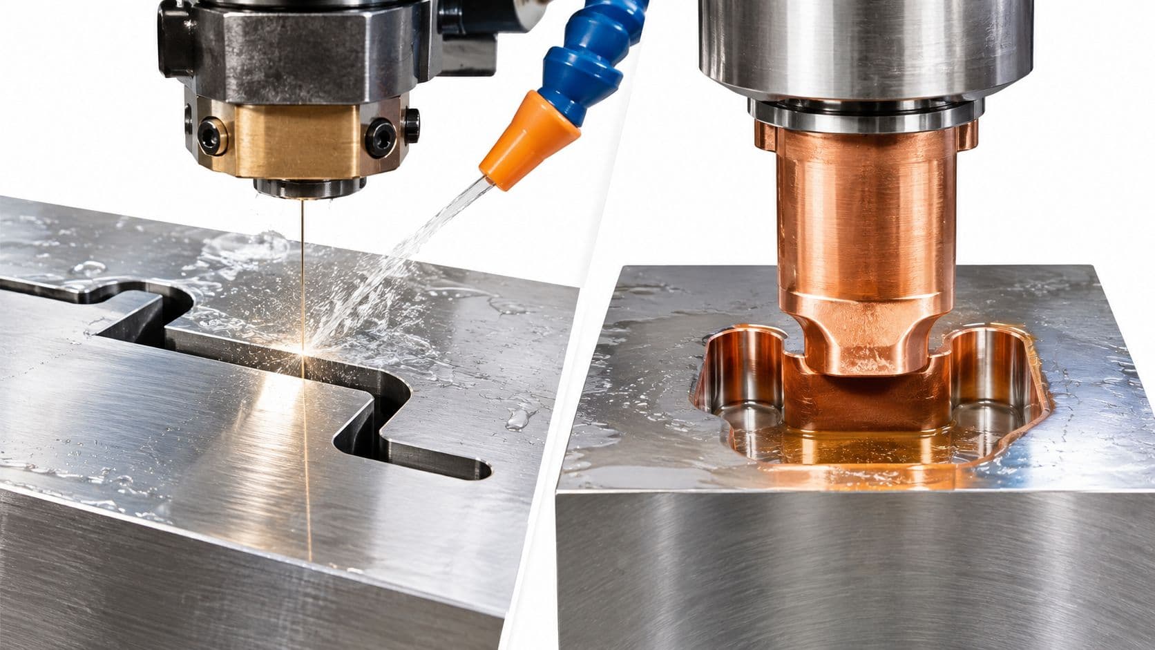
Wire EDM cuts through-profiles with a continuously fed wire electrode; sinker EDM forms blind cavities with a shaped electrode. That distinction matters more than a general claim about which machine produces a better finish.
For an initial process review, put the drawing beside this comparison.
Wire EDM vs sinker EDM at a glance
| Factor | Wire EDM | Sinker EDM |
|---|---|---|
| Electrode | Continuously fed wire, consumed as it cuts | Shaped electrode, usually copper or graphite, manufactured for the cavity |
| Geometry | Through-profiles and straight or contoured through-cuts | Blind cavities, ribs, deep pockets and sharp internal details |
| Start hole | Required for an enclosed internal cut; an accessible edge permits an edge start | Not required; electrode approaches from the surface |
| Tooling burden | Fixturing, programming and wire supply, without a cavity-shaped electrode | Electrode design, manufacture, inspection and wear management |
| Workpiece thickness | Check machine capacity, flushing and profile-control requirements | Check cavity depth, electrode reach and flushing access |
| Finish behaviour | Skim-pass strategy controls finish; corners can lag | Multiple finishing passes and orbital motion refine cavity surfaces |
| Best-fit parts | Punches, dies, gauges, slots and intricate profiles | Mould cavities, blind features and repeatable shaped cavities |
Both processes require an electrically conductive workpiece and a dielectric fluid. Conductivity is therefore a feasibility gate for EDM, not a useful way to choose between wire and sinker. Neither process is the direct answer for a nonconductive plastic component.
The tooling row deserves particular attention during sourcing. Wire EDM still needs process engineering, workholding and a cut sequence, even though it doesn't need a custom cavity electrode. Sinker EDM adds a separate toolmaking task before the workpiece can be finished.
Selection rule: Compare processes against the feature's constraints, not against a machine's best advertised result.
At FIRMFG, we offer wire EDM service. The appropriate route still starts with the drawing: neither EDM method is universally faster, cheaper or more accurate across every geometry and acceptance requirement.
How Each Process Removes Metal and Reaches the Feature
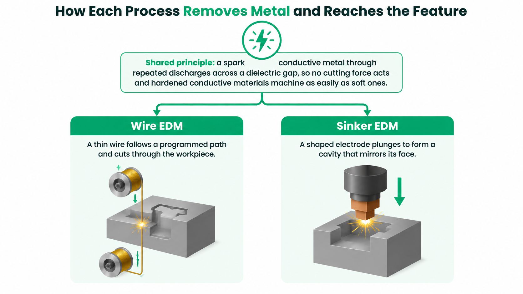
Both methods remove conductive metal through repeated electrical discharges across a dielectric gap. The electrode doesn't mechanically cut the workpiece, so conventional cutting forces aren't applied to the feature. Hardened conductive materials remain practical candidates, although hardness alone doesn't establish cutting speed or process stability.
The difference is how the electrode reaches the material that must disappear.
Follow the electrode's access path
In wire EDM, a tensioned moving wire follows the programmed profile while extending through the workpiece. An enclosed internal contour needs an opening through which the wire can be threaded. An external contour can instead begin from an accessible edge.
The technical document hosted by the German National Library describes wire EDM applications on workpieces up to approximately 300 mm thick, with achievable accuracy and productivity strongly influenced by wire tension, flushing, pulse settings, thickness and taper compensation. Treat that as a reported application range, not a guarantee for every profile at that thickness.
A wire-cut contour can be intricate, tapered or different between its upper and lower boundaries. It still needs a continuous through-path. For the machine sequence behind that constraint, our guide to how wire EDM works explains the relationship between the wire, discharge gap and programmed cut.
Sinker EDM uses a shaped electrode, commonly copper or graphite, that advances into the workpiece. The electrode geometry and controlled motion establish the cavity. The tool must have an approach path, working clearance and a way to maintain a stable discharge as debris leaves the gap.
Ask these access questions before comparing specifications
The practical geometry distinction described in MechCodex's guide to sinker EDM removal rate and overcut leads to a useful drawing review:
- Through or blind? Mark the intended floor of each pocket. A hidden bottom face changes the process choice.
- Can the wire be threaded? Identify an accessible start location and confirm that creating a start hole won't damage a retained surface.
- Is the depth or form shaped? A pocket with local depth changes needs more than a through-contour toolpath.
- Would a shaped electrode duplicate an accessible profile? If wire can cut the required contour directly, electrode manufacture may add work without adding capability.
Say a stamping die section has an intricate internal opening. Wire EDM follows the opening directly, without translating that contour into a separate electrode package. The planner still needs to control the cutout and protect the finished boundary when the scrap separates.
A mould insert with ribs and blind pockets presents a different problem. The cavity floor must remain intact, and the electrode must reproduce local negative details. Sinker EDM fits that access requirement, provided the electrode can approach and the narrow regions can be flushed.
A cavity that's enclosed against every possible electrode approach isn't automatically machinable just because sinker EDM makes blind features.
Don't classify every difficult feature as an EDM job, either. We offer 4-axis CNC machining for complex geometries and undercuts, so accessible features should also be reviewed for a conventional machining route. Mark the access direction, retained faces and prohibited start-hole locations before committing to tooling.
Tolerance, Surface Finish and Recast Layer Compared
Ra alone isn't an acceptance specification. It describes surface roughness, not the complete condition of the thermally affected material beneath the surface. A smooth-looking EDM feature can still require additional evaluation before it's accepted for fatigue, sealing, wear or medical-device service.
MechCodex's EDM guide distinguishes surface finish from subsurface integrity: higher discharge energy and longer pulse-on time increase crater size and recast depth, while lower-energy finishing improves roughness at the expense of cycle time. Sinker finishing can use multiple passes and orbital motion; wire finishing relies heavily on the skim-pass strategy.
Acceptance criteria by process
| Criterion | Wire EDM | Sinker EDM |
|---|---|---|
| Surface roughness (Ra) | Establish through a defined skim-pass strategy | Establish through finishing settings, electrode condition and orbital motion |
| Recast layer | Control discharge energy and pulse-on time; verify against the functional limit | Control discharge energy and pulse-on time; verify against the functional limit |
| Dimensional tolerance | Unconfirmed until the supplier approves the feature-specific requirement | Unconfirmed until the supplier approves the cavity-specific requirement |
| Main finish limit | Corner lag, kerf, wire deflection and flushing stability | Electrode wear and flushing in deep or narrow features |
Separate size, texture and surface integrity
Specify tolerance per critical feature, including the datum relationship that matters in assembly. A profile may satisfy its local width requirement while failing its location relative to a mounting face. Likewise, an acceptable measurement at the top of a cut doesn't establish compliance over the full depth.
Our wire EDM tolerances guide is a starting point for that discussion, not a replacement for drawing-specific confirmation. We offer standard CNC machining with ±0.005 inch (±0.13 mm) tolerance and high-precision machining with ±0.0005 inch (±0.013 mm) tolerance. Those are CNC machining capabilities, not blanket EDM guarantees.
For release, turn the functional requirement into explicit drawing notes or an accompanying acceptance specification:
- Surface texture: Identify the required Ra and the surfaces to which it applies.
- Pass strategy: Request the proposed roughing and finishing sequence where process qualification requires it.
- Surface layer: Define allowable recast or heat-affected material rather than assuming roughness controls it.
- Post-processing: Identify polishing or layer removal, including which dimensions apply afterward.
- Dimensional acceptance: State critical tolerances, datum references and corner requirements.
- Inspection: Agree on how texture, dimensions and any subsurface requirement will be verified.
For robotics hardware, a wear face may drive the finishing decision. For an automotive component, cyclic loading or sealing may make surface integrity more important than appearance. For a medical component, the responsible engineering team must establish the applicable material and surface acceptance requirements.
Inspect the final condition. If polishing follows EDM, acceptance must account for the geometry and surface left after polishing, not merely the as-machined cavity.
Tooling, Speed and Cost Tradeoffs by Volume
For a prototype with an accessible open profile, wire EDM usually avoids the largest extra task: manufacturing a shaped electrode. For repeated shaped cavities, sinker tooling becomes easier to justify because the same electrode strategy can support successive parts. A blind cavity on a single part is a feasibility decision before it's a volume calculation.
Cost and tooling by production situation
| Situation | Lower total cost usually | Main cost driver |
|---|---|---|
| Single prototype with open profiles | Wire EDM | No cavity electrode to design or inspect; lower tooling exposure |
| Small batch of open profiles | Wire EDM | Reusable programming and fixturing, balanced against profile length and finishing passes |
| Repeatable shaped cavity across many identical parts | Sinker EDM | Electrode cost spread across repeat cavities |
| Blind cavity needed, single part | Sinker EDM between these alternatives | Electrode tooling is required; no wire-versus-sinker break-even quantity applies to an inaccessible blind feature |
Separate removal rate from finished-part cost
Electrical settings change productivity and wear, not just surface texture. The experimental work discussed in the International Journal of Precision Engineering and Manufacturing identifies discharge current, pulse duration and voltage as significant influences on material-removal rate in aluminum 6061-T6, with pulse-series delay also affecting electrode wear; it also reports optimized sinking-EDM roughness of 0.329 and 0.728 micrometres Ra on refractory high-entropy alloys.
Those finish results are application-specific, not a universal ranking of the two methods. They demonstrate why a quote for a rough cavity and a quote for a finished functional surface aren't equivalent.
Wire EDM consumes wire and machine time. Longer profiles, thicker sections and additional skim passes increase the work required. Sinker EDM adds electrode engineering, fabrication and inspection, followed by wear management during machining.
Quoting caution: A lower roughing-cycle estimate doesn't establish a lower cost for an accepted part.
There's no defensible universal break-even quantity. Calculate it from the actual electrode package, replacement requirements, setup reuse, finishing cycle and inspection plan. A design revision that changes the cavity can also make previously manufactured electrodes unusable.
Include rework exposure in that comparison. Choosing a route that cannot preserve the pocket floor or meet the corner requirement can cost more than the machine-time difference being negotiated.
Request both quotations against the same material, stock thickness, profile complexity, target Ra, dimensional tolerance, corner radius and cavity requirements. Ask for tooling and recurring part costs separately, so procurement can distinguish an initial investment from the cost of repeat supply.
Which Process Fits Prototype and Production Parts
Choose by the feature being manufactured, not the industry label on the purchase order. A medical instrument and a stamping tool may both need a wire-cut contour, while unrelated products may share the same sinker-machined cavity geometry.
Recommended EDM process by part type
| Part type | Usually suited to | Deciding feature |
|---|---|---|
| Punches and die sections | Wire EDM | Through-profile with a sharp contour |
| Gauges and go/no-go plugs | Wire EDM for the applicable profile | Accurate through-profile, with finishing on wear faces |
| Through slots and keyways in hardened steel | Wire EDM | Accessible threading location or edge start |
| Mould cavities and inserts | Sinker EDM | Blind pockets, ribs and repeatable shaped form |
| Deep internal features with sharp corners | Sinker EDM | Reachable negative form that a wire cannot access |
| Bracket with a through slot vs a blind pocket | Wire EDM vs sinker EDM | Whether the bottom remains intact |
Watch the revision that changes the route
Say a bracket needs a through slot in a hardened section. With suitable threading access, wire EDM can generate that opening without a shaped electrode. If the designer revises the slot into a blind pocket to retain a sealing floor, the same route no longer produces the required part.
A corner requirement can change the decision too. Don't release a mathematically sharp internal corner without reviewing the physical electrode and discharge gap. Wire size and gap constrain a wire-cut corner; electrode geometry, wear and gap constrain the corresponding sinker detail.
For gauges, identify which surfaces perform the measurement. A wire-cut outline doesn't complete a plug gauge that also requires other dimensional forms or separately finished contact surfaces. Assign each operation to its functional feature rather than calling the whole component a wire EDM part.
Prototype planning tends to favour wire for accessible profiles because it avoids cavity-electrode lead time. Production planning can favour sinker for stable, repeated cavities, but only after the team approves the electrode and replacement strategy.
For medical or aerospace internal contours, access remains the first gate, followed by the required surface layer, finish and inspection evidence. Our overview of industrial CNC machining provides context for placing EDM within a broader machining route. A multi-process plan is often more defensible than forcing every feature onto the same machine.
Confirm the Process Before You Send the Drawing
Before requesting a price, make the critical inputs explicit. A quotation based on a model without surface requirements isn't directly comparable with one that includes finishing, surface-layer control and inspection.
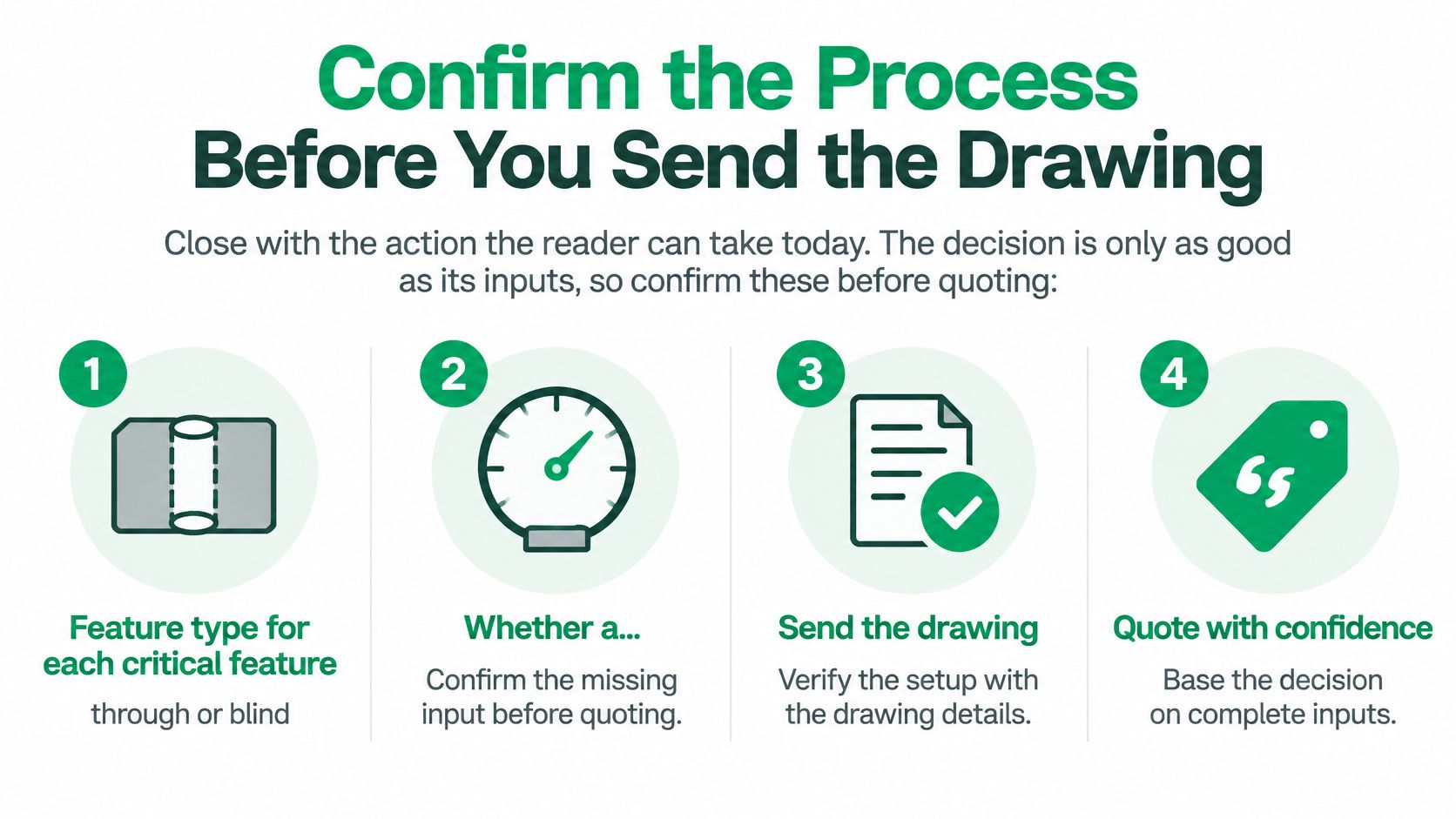
- Feature type: Mark every critical opening or cavity as through or blind.
- Wire access: Identify the permitted threading location and whether a start hole is acceptable.
- Workpiece condition: Supply the material grade, hardness condition and stock thickness.
- Surface acceptance: Specify Ra, allowable recast or heat-affected material, and the inspection method.
- Geometry acceptance: Identify critical dimensional tolerances, datum relationships and corner radii.
- Quantity: State the immediate order and expected repeat demand.
Send the same drawing revision and acceptance package for both process evaluations. Keep proposed concessions separate from the base quotation so a cheaper price does not hide a larger radius, omitted finishing operation or relaxed inspection requirement.
We provide free DFM feedback, with engineers reviewing designs and suggesting improvements for CNC machining. Use that review to identify access conflicts before releasing the manufacturing drawing, and distinguish confirmed wire EDM requirements from features that need another process.
Decide by feature access first, then confirm finish, layer and volume.
FIRMFG offers wire EDM service and free engineering DFM feedback to help review the drawing before machining. Visit FIRMFG with your model, controlled drawing and expected quantities to request a DFM review and discuss which features suit wire EDM.