How Does Wire EDM Work: A Practical Engineering Guide
A print lands on your desk with a narrow internal slot in hardened tool steel. The feature is too deep for a practical milling cutter, grinding would soften the internal geometry, and the material is already hardened. You need several matching parts, a controlled edge, and an inspection result you can defend.
That's the shop-floor situation where wire electrical discharge machining, or wire EDM, earns consideration. Instead of forcing a cutting tool through the workpiece, the machine guides a continuously moving wire along a programmed path and removes metal with electrical discharges. The wire never contacts the part, so the process can handle hard conductive materials and delicate profiles without ordinary cutting forces.
The useful question isn't only “how does wire EDM work?” It's also which part of the process controls material choice, accuracy, surface finish, cycle time, energy use, and inspection risk. The following walkthrough follows the job from the first spark to the final measurement.
Table of Contents
Inside a Wire EDM Machine Step by Step- The work tank and wire path
Materials, Geometry, and What the Wire Can Reach- Corner radius and feature planning
Tolerances, Surface Finish, and the Speed Trade-Off- Why skim passes matter
Where Wire EDM Earns Its Place- Comparing the alternatives
Inspecting a Wire EDM Part the Right Way- What to verify on the cut edge
Bringing It All Together Before You Quote
Why Engineers Ask How Wire EDM Works
Wire EDM becomes relevant when the drawing asks for a combination that conventional machining struggles to deliver. A hardened punch may contain a narrow slot, a small internal corner, or a profile that must remain stable through the full thickness. Milling can reach many shapes, but tool access, cutter diameter, tool deflection, and hardness can make the operation unattractive. Grinding can produce excellent surfaces, yet it isn't always suited to enclosed profiles or complex through-features.
The process has a long technical history. Its modern development traces to the 1940s work of Soviet researchers B. R. and N. I. Lazarenko, whose controlled electrical-discharge method became the basis for later wire cutting. Commercial wire EDM machines appeared in the 1960s, and Agie produced the world's first wire EDM machine in 1969, as documented in this history of EDM machining.
Early machines were slow. A historical handbook reports cutting rates of about 2 square inches per hour, or 21 mm²/min, in the early 1970s, while machining rates had improved to about 64 mm²/min by the 1980s, according to the same historical reference. Those figures help explain why wire EDM first found a natural home in precision tooling and difficult materials, then became a practical production process as controls, generators, flushing, and wire systems improved.
Practical rule: Choose wire EDM because the feature, material, or tolerance makes contact cutting inefficient or risky, not simply because the machine can produce a fine-looking edge.
Think of the machine as a guided tour with four stops: the electrical gap, the wire path, the work tank, and the inspection bench. Once you understand what happens at each stop, quoting and process selection become much more straightforward.
The Physics Behind the Spark
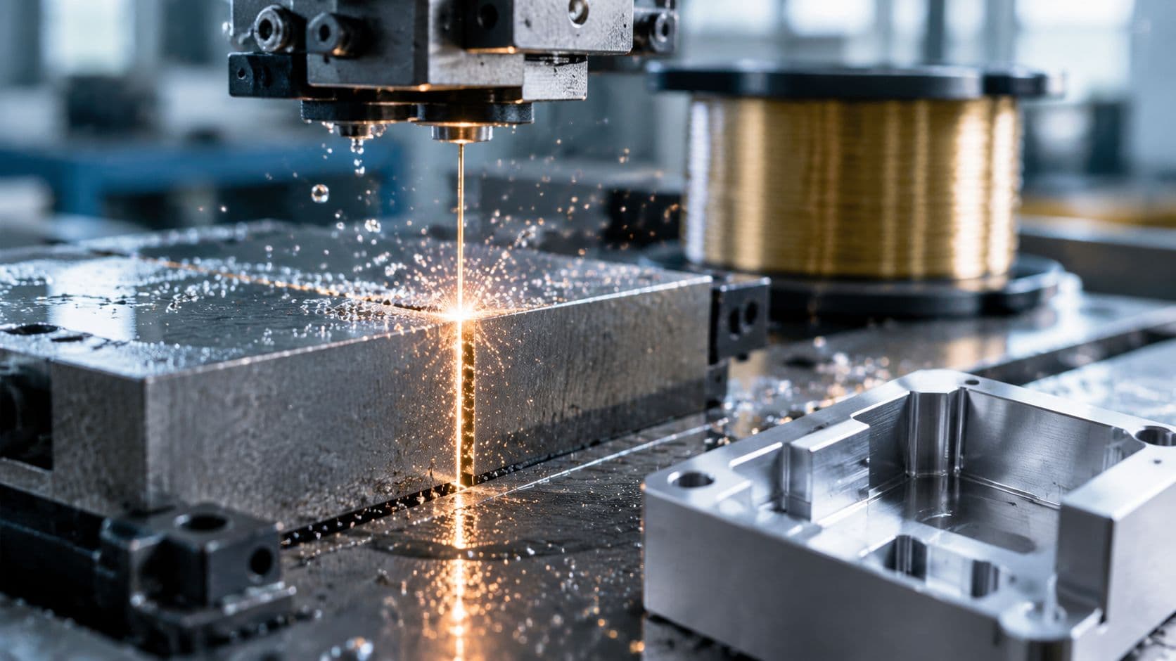
At the cutting zone, the wire and the workpiece act as two electrodes. The wire is commonly brass or zinc-coated metal, and the workpiece must be electrically conductive. A very small gap separates them, while deionized water surrounds the cutting area and serves as the dielectric.
The sequence resembles a tightly controlled lightning storm. The dielectric initially insulates the wire from the part. When the electric field becomes strong enough, the water breaks down and a plasma channel forms across the gap. Local temperatures can reach roughly 8,000 to 12,000°C, causing a microscopic area of metal to melt and vaporize, as described in this wire EDM engineering guide.
The discharge lasts for a short pulse, then collapses. Water carries away molten debris and cools the cutting zone. The generator establishes another controlled pulse, and the cycle repeats. One industry explanation states that this discharge can occur up to 250,000 times per second, with the water also helping stabilize the process and protect the wire, as explained in how wire EDM works.

How settings change the result
The operator and CNC control manage the discharge as a repeating electrical process, not as one continuous arc. Pulse-on time and current affect how aggressively each discharge removes metal. Longer or stronger pulses can increase removal, but they also increase the thermal effect at the edge and can worsen surface roughness.
Pulse-off time gives the dielectric an opportunity to recover and flush debris from the gap. If debris remains, the gap can become unstable, causing short circuits, erratic sparks, or wire breakage. This is why flushing isn't a support function added around the cut. It's part of the cutting mechanism.
Because the wire never pushes against the workpiece, wire EDM applies no conventional mechanical cutting force. That non-contact behavior lets it machine hardened steel, tungsten carbide, and other difficult conductive materials without the tool pressure and distortion associated with physical cutting.
Inside a Wire EDM Machine Step by Step
Start at the programming station. The operator imports the CAD geometry, defines the profile, selects the cutting technology, and identifies how the wire will enter the workpiece. A through-feature usually needs a start hole, so the programming decision includes not just the final contour but also the path used to reach it.
The machine then feeds wire from a spool through guides and tension controls. Fresh wire continuously enters the cutting zone and used wire is collected, so the cutting electrode doesn't rely on one section of wire for the entire job. Typical wire diameters are about 0.05 to 0.3 mm, and another technical reference gives a common working range of about 0.10 to 0.30 mm, depending on the application and machine setup.

The work tank and wire path
The operator fixtures the conductive workpiece on the table, aligns it to the machine coordinates, and brings the start hole into position. The work area fills with deionized water, which insulates the gap before each discharge, flushes eroded particles away, and carries heat from the cutting zone.
Upper and lower guides hold the wire on its intended path. The CNC system moves the table and guide system along the programmed contour while servo control continually adjusts the wire-to-part gap. For a straight cut, the wire remains close to vertical. For a tapered or angled feature, the upper and lower guide positions differ so the wire follows the required profile through the material.
The machine's nozzles direct dielectric flow toward the spark gap. Operators watch flushing pressure, wire tension, electrical response, and cutting stability because a visually simple profile can still fail if debris accumulates in a deep or narrow section.
If the wire breaks, the machine must stop, rethread, and recover from a known position. A stable spark gap is therefore a quality requirement as much as a productivity requirement.
After the roughing cut and any programmed skim passes, the part is removed from the tank and cleaned. Deionized-water residue and loose debris must be removed before inspection, especially when a small feature or tight fit will be measured with optical equipment.
Materials, Geometry, and What the Wire Can Reach
The first feasibility question is electrical, not mechanical: can the workpiece conduct electricity? Wire EDM is intended for conductive materials. Tool steels, carbide, titanium, copper, and other conductive metals can respond to the discharge process. Plastics and non-conductive ceramics generally fall outside the process because the electrical circuit cannot form the controlled spark channel needed for erosion.
Material hardness matters less than it does in milling because the wire doesn't cut by shearing the surface. That makes wire EDM useful for hardened tooling and difficult alloys, provided the material is conductive and the part can be fixtured, submerged, and reached by the wire.
Geometry is the second filter. The wire can create narrow slots, internal profiles, and corners that would require a very small milling tool or a sequence of secondary operations. A wire cut also creates a kerf, so the programmed path must compensate for the wire diameter and the discharge gap.
Corner radius and feature planning
A wire is round, which means an internal corner can't be perfectly sharp. The achievable radius depends on wire diameter, discharge conditions, corner strategy, and the required finish. A thicker wire produces a larger practical corner radius, while a finer wire can support smaller details but may reduce cutting stability.
Taper adds another design variable. A modern multi-axis machine can tilt the wire to create angled walls or changing profiles through the thickness. That capability is valuable for dies, punches, and matched components, but the drawing should state the intended wall angle and the reference surfaces used for inspection.
Use this quick comparison as a screening tool rather than a substitute for a supplier review:
| Material | Cutability | Typical Min. Corner Radius | Notes |
|---|---|---|---|
| Hardened tool steel | Suitable if conductive | Depends on wire and settings | Useful for punches, dies, and hardened profiles |
| Tungsten carbide | Suitable if conductive | Depends on wire and settings | Requires controlled energy and stable flushing |
| Titanium | Suitable if conductive | Depends on wire and settings | Confirm flushing, thickness, and surface requirements |
| Copper | Suitable if conductive | Depends on wire and settings | Electrical behavior can require tailored parameters |
| Graphite | Process-dependent | Depends on setup | Confirm machine, dielectric, and debris-control strategy |
| Plastic or non-conductive ceramic | Generally unsuitable | Not applicable | The electrical discharge circuit cannot operate conventionally |
If a part is conductive but has no enclosed feature, no extreme hardness issue, and no demanding profile, milling or grinding may be faster and more economical. Wire EDM becomes compelling when access, hardness, internal geometry, or distortion risk dominates the decision.
Tolerances, Surface Finish, and the Speed Trade-Off
Wire EDM quality comes from controlling several competing variables. A roughing pass removes material efficiently, but its higher discharge energy leaves a more thermally affected edge. A finish pass uses gentler conditions to refine the contour and reduce the recast layer. The controller and process engineer must decide how much material to remove aggressively and how much time to spend correcting the resulting geometry and surface.
Independent technical references report optimized performance around ±0.0001 inch accuracy on thick carbide with a 5 microinch Ra finish, while common tuned finish cuts can reach Ra 0.3 µm or better, according to this technical overview of wire EDM process quality. Treat those values as process-dependent targets, not automatic results. Thickness, material, geometry, flushing, wire condition, thermal stability, and inspection method all influence the outcome.

Why skim passes matter
The first cut establishes the opening and removes most of the stock. It also creates the largest thermal and debris-management burden. Subsequent skim passes follow the same contour with lower energy, removing a small amount of material and correcting the edge left by the previous pass.
That's the central tradeoff. More aggressive settings favor speed and removal. More controlled finish passes favor surface integrity and dimensional refinement. Continuous dielectric flushing remains critical because it clears debris from the gap, prevents short-circuiting, and stabilizes the discharge. Inadequate flushing directly harms roughness and cutting consistency.
Pulse on-time and current strongly influence both material removal rate and surface roughness. Research using optimization methods including ANN, GA, and RSM has reported predictive accuracy above 95%, while a newer energy model reported 98.06% accuracy for process-wide energy prediction in the cited wire EDM energy and sustainability research. That research also reported that low-energy optimization reduced energy use by 11.5% and carbon emissions by 5.74% versus traditional settings.
For tolerance planning, don't specify the tightest possible value by habit. A tolerance such as ±0.0001 inch may be achievable, but every extra pass and verification step affects cycle time and cost. Compare the required fit, function, and sealing or sliding condition against the broader guidance in this CNC machining tolerances guide.
Engineering decision: Ask the supplier to quote the rough cut and finish-pass strategy separately. “Fine finish” isn't a complete process instruction unless the number of passes, target roughness, and recast acceptance are defined.
Where Wire EDM Earns Its Place
Wire EDM earns its place when the geometry is difficult for a rotating tool, the material is already hard, or the part must remain dimensionally stable during cutting. A punch and die set is a clear example. The mating profiles may require close coordination, and internal corners or narrow openings can make conventional tool access awkward.
Aerospace components can present another use case. Blade roots and fir-tree slots contain repeating details that may be difficult to mill after heat treatment. Wire EDM can follow the profile through hardened conductive stock while avoiding physical cutting pressure. The process still requires careful programming and inspection, particularly where taper, wall condition, and surface integrity affect assembly.
Medical components often demand small, clean features. A bone-drill edge, instrument profile, or compact guide component may benefit from the wire's narrow kerf and non-contact action. The material and cleanliness requirements must be specified, because an electrically conductive material isn't automatically suitable for every medical application.
Comparing the alternatives
Milling remains the better choice when the geometry is open, the material is easy to cut, and material removal speed matters more than a narrow internal profile. Turning is the natural choice for rotational parts. Grinding can outperform wire EDM where the design calls for a straightforward accessible surface and the finish requirement dominates.
Wire EDM is strongest in a different zone:
- Deep narrow features: The wire can pass through a start hole and cut an enclosed profile that a milling cutter may not reach effectively.
- Hardened conductive stock: The process doesn't depend on a sharp mechanical edge surviving contact with the workpiece.
- Complex through-profiles: CNC motion can follow contours, while multi-axis control can create tapered walls.
- Small-batch tooling: A difficult hardened insert may justify the setup because avoiding multiple specialized cutting tools reduces process risk.
- Low-force cutting: Thin walls and delicate sections don't experience ordinary cutter pressure, although thermal and residual-stress effects still require control.
The key is to compare the whole route, not one operation. A fast rough mill followed by grinding may beat wire EDM for a simple feature. For a hardened part with internal geometry, wire EDM may eliminate several workarounds and reduce the chance of distortion or rework.
Inspecting a Wire EDM Part the Right Way
Inspection starts before the part reaches the bench. Clean the workpiece thoroughly, identify the datum structure from the drawing, and confirm that the measurement method matches the feature. A digital caliper is useful for a quick overall check, but it isn't enough for a narrow slot, a small internal corner, or a profile where wire compensation affects the result.
Use calibrated calipers for accessible dimensions, pin gauges for suitable internal openings, and thread gauges where the drawing calls for a threaded feature. An optical comparator can reveal profile errors and corner-radius behavior without forcing a contact probe into a delicate edge. For complex coordinate relationships, a coordinate measuring machine may be appropriate. FIRMFG describes its CMM inspection services as part of a broader dimensional verification workflow.

What to verify on the cut edge
Surface roughness needs its own measurement. A profilometer should assess representative areas rather than relying on appearance alone. Check the entry, middle, and exit zones when thickness or flushing could create variation through the cut.
Inspectors should also look for EDM-specific conditions:
- Recast layer: The resolidified material on the cut edge can matter for fatigue-sensitive or heat-treated components.
- Microcracks: Magnified inspection may reveal thermal damage that a caliper cannot detect.
- Taper: Compare dimensions at relevant heights when the wall must remain parallel or follow a controlled angle.
- Wire marks: Fine linear marks can be a normal process fingerprint, but their severity should match the specified finish.
- Residue: Remove dielectric residue and loose particles before sign-off so contamination doesn't affect assembly or later processing.
Record the material and certificate, drawing revision, measured dimensions, roughness result, inspection equipment, and any agreed acceptance criteria for recast or taper. If the part went through stress relief or another post-cut treatment, retain the corresponding evidence with the inspection record. The goal isn't to produce a measurement number in isolation. It's to show that the finished feature matches the design intent and the process assumptions used during quoting.
Bringing It All Together Before You Quote
A useful wire EDM RFQ begins with four gating questions. First, is the material electrically conductive? If it isn't, the process cannot operate in its conventional form. Second, does the part contain a through-feature, internal profile, sharp corner requirement, or hardened section that makes milling, turning, or grinding less attractive?
Third, what does the part need for tolerance and surface roughness? A drawing that specifies a demanding value without a functional reason can force unnecessary skim passes. Fourth, does the geometry require taper control, multi-axis motion, submerged cutting, or a carefully defined start-hole location?
Use the design review principles in this design for manufacturability guide before sending the model. A supplier can quote more reliably when the material condition, thickness, datums, quantity, critical features, finish target, and inspection expectations are clear.
| Part Characteristic | Recommended Process | Wire EDM Advantage |
|---|---|---|
| Open profile in soft conductive stock | Milling | Wire EDM may be unnecessary |
| Rotational geometry | Turning | Wire EDM offers little benefit |
| Accessible flat precision surface | Grinding | Grinding may provide a more direct route |
| Hardened internal profile | Wire EDM | Non-contact cutting avoids conventional tool pressure |
| Tapered through-feature | Multi-axis wire EDM | Controlled wire angle can form the wall profile |
| Fine slot or intricate punch profile | Wire EDM | Narrow wire access supports complex contours |
| Conductive delicate section | Wire EDM or careful milling | Minimal mechanical cutting force |
Before approval, ask the supplier to state the finish-pass intent, expected recast condition, material certification requirements, lead time assumptions, and inspection method. Confirm whether the available wire type and diameter suit the feature, and make sure the quote distinguishes a rough cut from a multi-pass finished profile.
Wire EDM isn't the default answer for every precision part. It's a specialized process that becomes valuable when electrical conductivity, hardness, access, geometry, and surface integrity point in the same direction.
If you're evaluating a conductive hard-metal part or a complex profile, FIRMFG offers wire EDM alongside CNC machining, inspection, and other manufacturing processes. Send the drawing and material condition for a process review that connects tolerance, finish, skim-pass strategy, and inspection requirements to a practical quote.