Wire EDM Tolerances: A Precision Engineering Guide
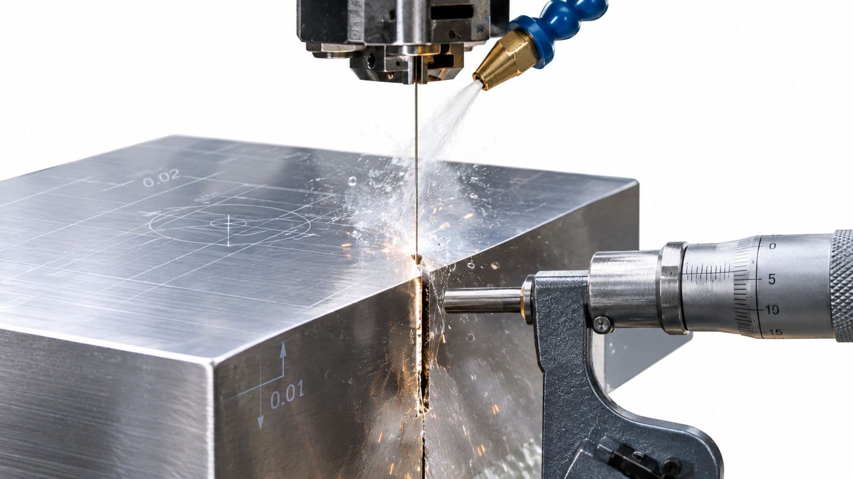
Ultra-precision wire EDM can technically approach approximately ±0.002 mm under ideal conditions, but a more reliable production expectation is typically ±0.005 mm to ±0.020 mm, depending on geometry, material, thickness, and process complexity. The practical answer is that wire EDM tolerances belong on a part drawing only after the machine, process, and inspection method have been matched to the feature.
A surprising result from experimental work is that wire EDM accuracy isn't a fixed machine specification. In one investigation, dimensional performance was lower than expected and linear precision was substantially poorer than CNC end milling under the tested conditions. That doesn't make wire EDM a poor precision process. It means the shop must control the complete process rather than copy the smallest number from a machine brochure.
The useful distinction is between machine capability, achieved part accuracy, and functional suitability. A machine may demonstrate exceptional positioning performance in a controlled test, while a thick, heat-treated component with deep internal corners, unstable flushing, or thin unsupported sections produces a different result. The drawing, cutting strategy, and inspection plan must reflect that difference.
Table of Contents
Key Factors Affecting Dimensional Accuracy- Why cutting passes change the result
Tolerance vs Surface Integrity and Functional Accuracy- Separate the acceptance criteria
Design Guidelines for Tight Features and Complex Geometries- Build the drawing around function
Wire EDM vs Other Precision Machining Processes
Inspection and Measurement Practices for Verified Accuracy- Measure the conditions that can fail
Practical Tolerance Examples for Common Alloys
Achievable Wire EDM Tolerance Ranges
Wire EDM capability is not the same as finished-part accuracy. A fine wire and non-contact cutting do not guarantee a fine result. Spark-gap stability, wire behavior, workpiece condition, flushing, thermal control, geometry, and the number of roughing and skim passes all affect the dimension that reaches inspection.
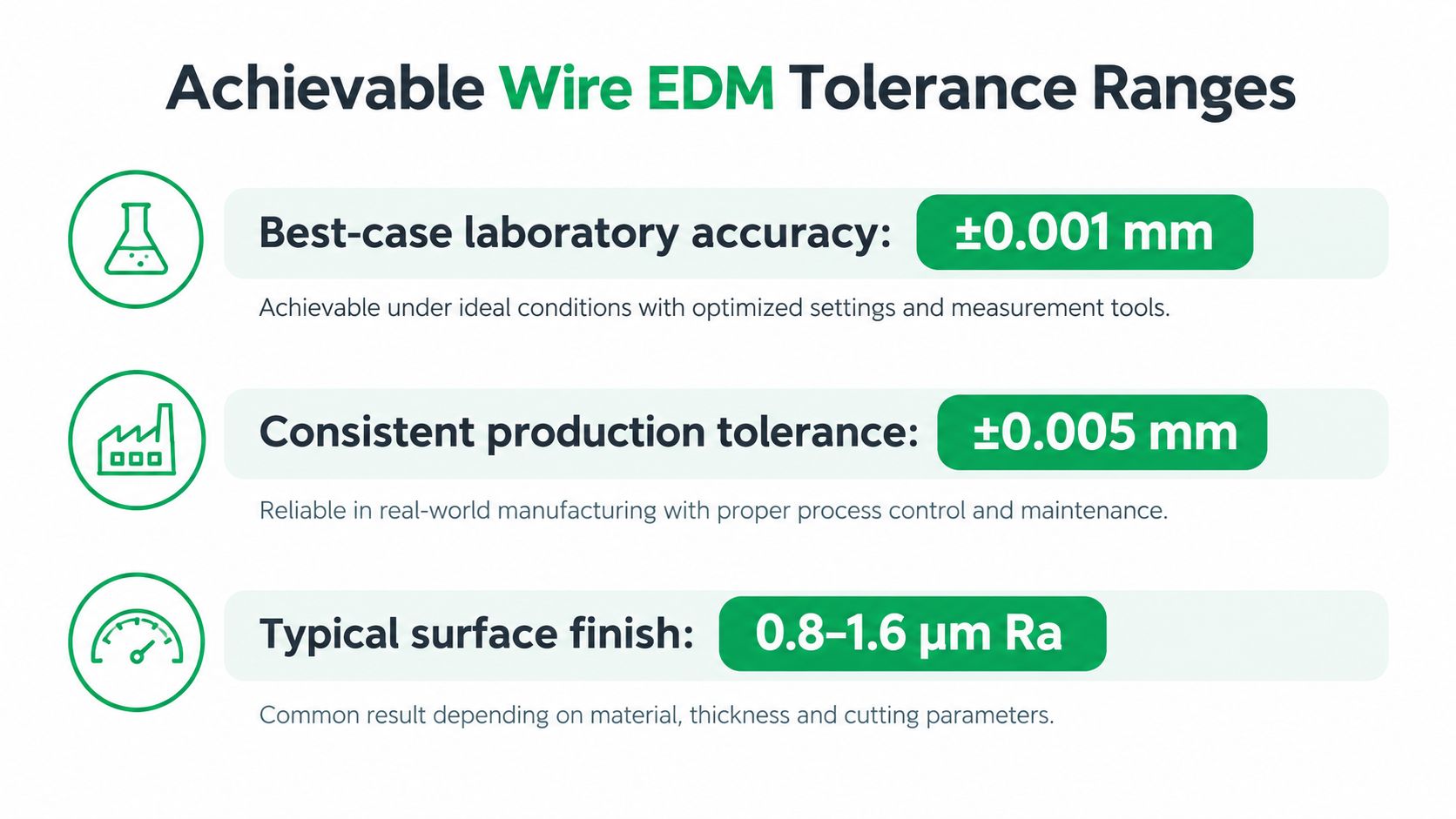
Laboratory reviews report positioning accuracy approaching 0.2 micrometers under controlled conditions, but finished-part tolerances on production drawings are far more conservative. Standard EDM capability is commonly described around ±0.005 mm to ±0.020 mm. Ultra-precision systems may approach approximately ±0.002 mm to ±0.005 mm when material, fixturing, compensation, wire tension, and the finishing sequence are tightly controlled. The distinction between controlled machine performance and production results is discussed in the technical review of WEDM dimensional control.
Read tolerance numbers correctly
A bilateral tolerance permits variation on both sides of nominal. ±0.005 mm represents a total dimensional window of 0.010 mm, or 10 micrometers. That window applies to the specified feature. It does not automatically control taper, flatness, perpendicularity, or position.
Apply the tightest tolerance only where assembly or function requires it. Less demanding features should carry practical limits that account for material behavior and the cutting sequence. FIRMFG's guidance on CNC machining tolerances follows the same principle: tolerance should reflect function, not machine resolution alone.
Practical rule: Treat the smallest published accuracy figure as a process-capability reference, not a default production promise.
A rough cut, finished profile, and profile refined through multiple skim passes represent different manufacturing conditions. The quotation should identify which condition supports the requested tolerance. For a feature that governs fit or operation, request representative first-article data rather than accepting a generic claim of micron-level control.
Key Factors Affecting Dimensional Accuracy
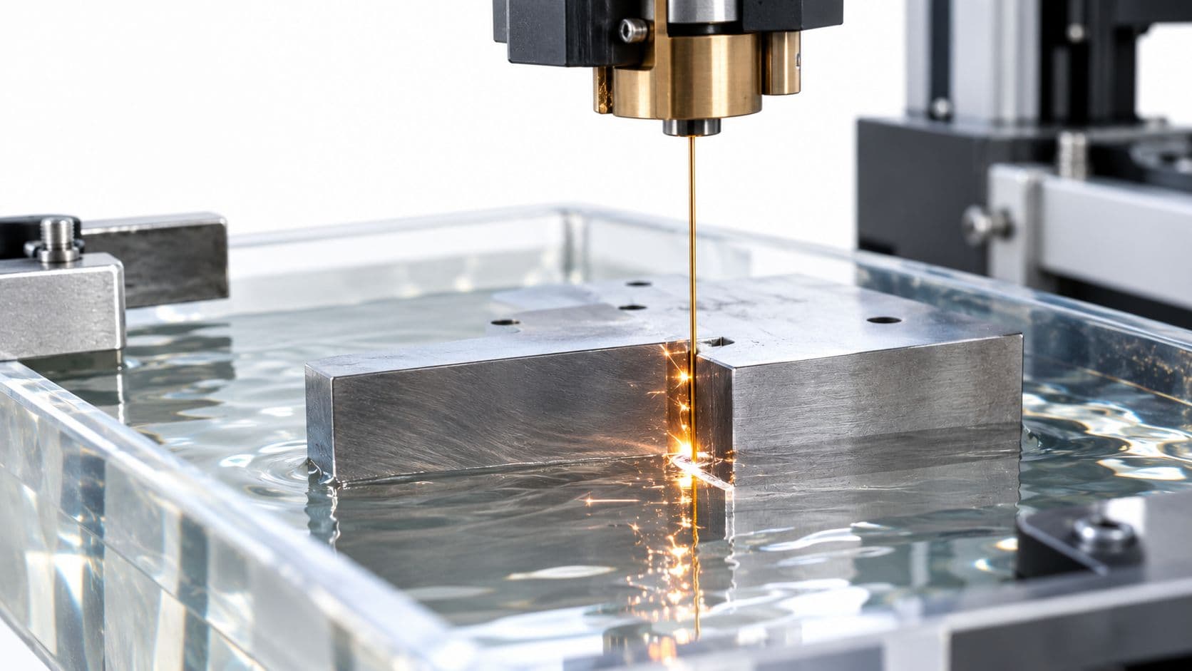
Machine capability does not equal part accuracy. The wire does not follow a perfectly rigid mathematical path through the workpiece. Electrical discharges, flushing pressure, wire tension, wire wear, material thickness, and changes in direction all influence the actual kerf and profile. The fundamentals are covered in this overview of how wire EDM works.
The main controllable variables include:
- Discharge current and pulse duration: Higher energy can increase removal rate, but it also changes crater size, thermal loading, roughness, and the damaged surface layer.
- Pulse-gap frequency: The timing between discharges affects spark stability and the consistency of material removal.
- Wire speed and tension: Stable tension limits wire movement. Vibration or excessive deflection can affect corners, straightness, and the final profile.
- Dielectric flow: Flushing removes eroded particles and stabilizes the cutting zone. Poor flow can produce unstable discharges, local overcutting, and wire breakage.
- Workpiece thickness and geometry: Long cuts, deep sections, narrow slots, internal corners, and changing wall conditions increase the opportunity for wire lag and taper.
A 2010 experimental investigation evaluated linear dimensional error, flatness error, and perpendicularity error while varying discharge current, pulse duration, pulse-gap frequency, wire speed, wire tension, and dielectric-flow rate. Its production lesson was direct: dimensional accuracy depends on the combined process settings, and the tested linear precision was substantially poorer than CNC end milling under those conditions. The study is documented in this WEDM parameter and accuracy investigation.
Why cutting passes change the result
The roughing pass prioritizes material removal. It leaves more thermal and geometric correction for later, so a feature requiring tighter control or better surface condition usually needs one or more skim passes.
A skim pass removes controlled stock from the rough profile and can improve dimensional consistency, straightness, corner definition, and surface quality. It cannot correct a thin section that moves after release, or a part that shifts while its thermal condition changes. Those failure modes must be addressed through support, workholding, and process setup.
The compensation model also needs representative inputs. A setting that performs well on a thin, straight profile may not transfer directly to a thick profile with tight internal corners. Material grade, hardness, thickness, cut height, flushing access, and required taper belong in the process review.
Wire EDM accuracy comes from a stable process window, not from one parameter adjusted in isolation.
Designers should separate size from form. Flatness, perpendicularity, taper, and profile error can fail independently of a nominal slot width. A drawing that specifies only a plus-or-minus size tolerance leaves the supplier to infer the geometric conditions that control assembly. FIRMFG's guidance on CNC machining tolerances follows the same principle: tolerance should reflect function, not machine resolution alone.
Tolerance vs Surface Integrity and Functional Accuracy
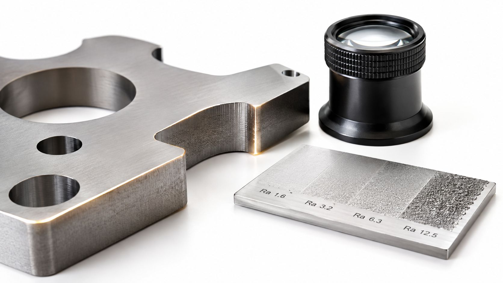
A part can measure within its dimensional tolerance and still be unsuitable for service. Wire EDM removes material thermally, so the electrical settings influence not only size but also kerf shape, wire wear, thermal deformation, recast-layer thickness, residual stress, roughness, and microcracking.
Higher discharge energy can raise cutting productivity while increasing roughness, recast-layer thickness, and residual stress. Research on Inconel 718 reports EDM recast layers typically around 5 to 9 micrometers, as described in this study of EDM surface integrity. That layer may matter more than a small coordinate error when the component sees fatigue loading, sliding contact, corrosion exposure, or biological requirements.
Separate the acceptance criteria
A drawing for a critical wire EDM component should consider separate requirements for:
- Dimensional accuracy: Does the feature size meet the bilateral tolerance?
- Repeatability: Do multiple parts hold the same result under the same setup?
- Form and profile: Are straightness, roundness, profile, or corner conditions acceptable?
- Taper: Does the entry profile match the exit profile through the full thickness?
- Surface roughness: Is the finished surface suitable for contact, sealing, fatigue, or appearance?
- Metallurgical condition: Are recast material, heat-affected regions, residual stress, and microcracks controlled?
- Inspection method: Can the selected equipment resolve the requirement with known uncertainty?
This matters for medical, automotive, aerospace, and fatigue-loaded components. A feature that measures within ±0.01 mm may still fail if a brittle recast layer or microcracks become the actual failure mechanism. The dimensional result and the surface-integrity result need separate evidence.
Reducing the nominal tolerance alone may not improve performance. It can encourage additional finishing passes, slower cutting, or higher inspection effort without addressing the material damage that limits service life. Specify the functional risk first, then select the dimensional, surface, and metallurgical controls that address it.
Design Guidelines for Tight Features and Complex Geometries
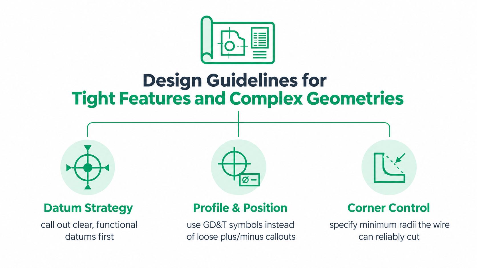
Tight wire EDM features start with a clear drawing, not with a request for the smallest possible tolerance. The supplier needs to know which surfaces establish the part, which features locate it, and which dimensions affect assembly or performance.
Build the drawing around function
Use a datum structure that reflects how the component is assembled or inspected. Then specify profile, position, parallelism, and perpendicularity separately from feature size. A slot can have the correct width while being misplaced, tapered, or out of perpendicularity through the material.
Include the conditions that affect process selection:
- Material and hardness: State the actual grade and heat-treatment condition, not just “tool steel” or “stainless.”
- Maximum thickness: Thick sections increase the importance of wire deflection, flushing, taper, and thermal behavior.
- Critical geometry: Identify thin ribs, narrow slots, internal corners, long profiles, and intersecting features.
- Taper requirement: Call out whether the entry and exit profiles must match or whether a controlled taper is acceptable.
- Pass strategy: State whether the requirement applies after roughing or after final skim passes.
- Inspection basis: Define datums, temperature, measurement equipment, and the reporting format.
The ISO 14137:2015 standard for wire-EDM machine tests standardizes geometric, positioning, repeatability, machining, and circular tests for general-purpose, normal-accuracy wire EDM machines. It verifies machine performance, however, it doesn't guarantee the dimensional tolerance of a finished component.
Avoid over-specification
A drawing that applies ±0.002 mm to every feature may force a finishing strategy that adds time without improving the part's function. A better approach is to reserve ultra-tight requirements for critical interfaces and use appropriate profile or location controls for the rest.
For deep cuts and thin sections, ask the supplier to inspect both entry and exit profiles. A nominally correct two-dimensional path can still produce out-of-plane error. Also provide enough stock or access for threading and fixturing, because a theoretically machinable profile may be impractical if the wire can't reach the starting location or the part can't remain stable after separation.
Design advice: Specify the feature that controls the assembly, then specify the inspection method that proves it. Don't substitute a smaller size tolerance for missing geometric controls.
Wire EDM vs Other Precision Machining Processes
Machine capability does not equal finished-part accuracy. Wire EDM can hold a tight programmed path, yet the part may still show taper, recast material, heat-affected areas, or distortion after separation. The useful comparison is therefore not one tolerance number. It includes dimensional control, surface integrity, material behavior, and the inspection required to verify the result.
Wire EDM suits conductive materials, hardened stock, thin sections, and intricate through-profiles that would be difficult to cut with a rotating tool. Because the wire does not contact the workpiece, cutting forces remain low. Thermal effects still need control, especially where the drawing limits surface condition or the material responds poorly to heat.
CNC milling offers broader access to three-dimensional surfaces, blind pockets, bosses, and threaded features. It is often faster for open geometry and parts that do not require a through-profile. Micro-milling can work efficiently for small accessible features, provided tool runout, rigidity, engagement, and material condition remain controlled. Grinding is generally the better choice for accessible datum surfaces, flatness, controlled finish, or final sizing.
| Process | Typical tolerance | Best for |
|---|---|---|
| Wire EDM | ±0.005 mm to ±0.020 mm typical, tighter with skim passes and controlled inspection, as discussed in the WEDM accuracy review | Through-profiles, hardened conductive materials, narrow slots, thin sections, and intricate internal outlines |
| CNC milling | ±0.01 mm to ±0.05 mm typical for prototype milling, setup-dependent | Accessible three-dimensional features, pockets, bosses, threaded details, and prototype work |
| Micro-milling | Application-specific, sensitive to tool size, runout, rigidity, and material behavior | Small accessible features where tool access and mechanical cutting are manageable |
| Grinding | Application-specific, with strong dependence on setup and workholding | Flat surfaces, controlled finishes, and final sizing after another process |
| Sinker EDM | Application-specific, dependent on electrode quality, wear, and process control | Blind cavities, three-dimensional pockets, and undercuts that wire EDM cannot create directly |
Choose the process from the geometry and functional requirement, not habit. Wire EDM is usually effective for flat or slightly tapered profiles through hardened material. Milling is commonly more efficient for open three-dimensional forms. Sinker EDM handles blind cavities, while grinding can establish accurate accessible surfaces.
Cost also includes programming, workholding, electrode preparation, skim passes, inspection, and possible secondary finishing. The process with the smallest nominal tolerance is not automatically the lowest-cost or most accurate functional solution. Surface damage, material movement, and measurement method can determine whether the completed part performs as intended.
Inspection and Measurement Practices for Verified Accuracy
A supplier's capability statement isn't proof that a particular part meets its drawing. Verification begins by defining how the part will be located, measured, and reported.
For a critical wire EDM component, create a first-article measurement plan before cutting:
- Define the datum reference frame. The inspection setup should reproduce the functional way the part is located.
- List critical characteristics. Include size, profile, position, flatness, perpendicularity, taper, and any surface-integrity requirements.
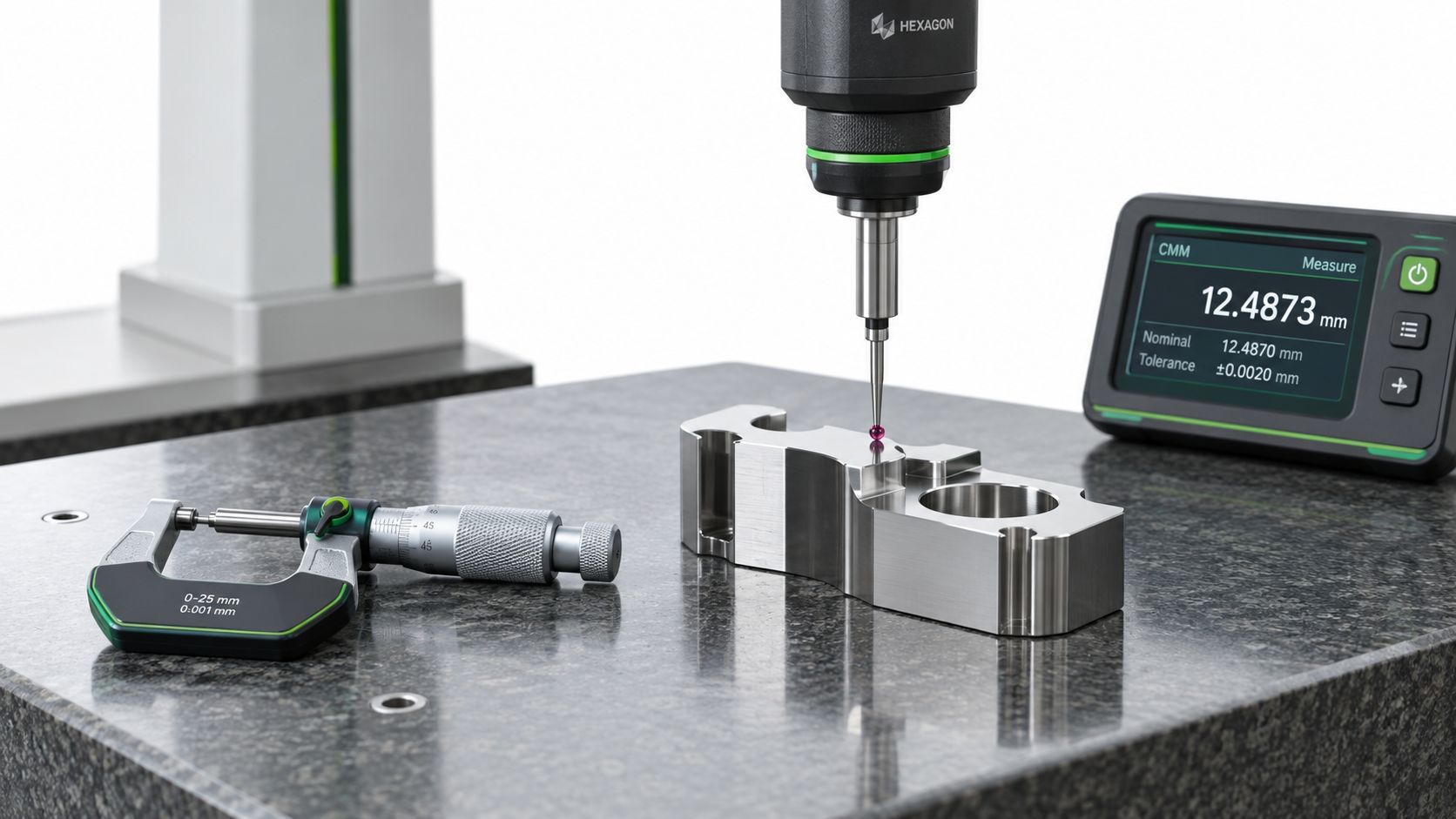
- Select suitable equipment. A calibrated CMM can evaluate profile and geometric relationships, while optical equipment can help inspect small outlines and delicate features.
- Control the measurement condition. Record temperature and support conditions when thermal movement or thin-section distortion could affect the result.
- Report the actual values. A pass or fail statement is less useful than nominal, deviation, tolerance, datum, and measurement method.
Measure the conditions that can fail
Don't inspect only the easiest accessible dimension. For a deep or thin profile, check entry and exit geometry, taper, and the relationship to the specified datums. A slot width measurement can't reveal whether the slot is tilted, bowed, or incorrectly positioned.
Surface roughness equipment should be used when the finish affects sliding, sealing, fatigue, or coating performance. Metallographic inspection may be appropriate when the application controls recast material, microcracks, or heat-affected regions.
A first article should also confirm the supplier's process assumptions. If the drawing requires final skim passes, the inspection report should identify the completed pass condition. If the supplier measured a rough cut and the customer expects a finished profile, the two parties aren't validating the same feature.
For projects that need documented dimensional evidence, define the scope of CMM inspection services during quotation rather than requesting a report after production. The inspection method is part of the manufacturing specification, not an administrative add-on.
Practical Tolerance Examples for Common Alloys
Material selection changes the process window even when the geometry stays the same. Hardened tool steels are often predictable for wire EDM because the process avoids the cutting-force and tool-wear problems associated with conventional machining after heat treatment. The drawing should still control taper, profile, and surface condition rather than assuming hardness guarantees accuracy.
Aluminum conducts electricity well, but debris management and flushing can become more demanding, particularly in thicker sections. Thin aluminum features may also move after release because residual stress and low stiffness can dominate the final position.
Titanium needs careful control of energy and flushing. Its thermal behavior can increase sensitivity to local heating, and the material is particularly vulnerable to wire breakage and recast-layer formation. A titanium part with a tight dimensional callout should therefore include a surface-integrity review, not just a CMM requirement.
Superalloys such as Inconel can be machined by wire EDM, but the process engineer must balance removal rate against thermal damage and inspection requirements. The same nominal tolerance may be reasonable for a stable straight profile and unrealistic for a thick, complex contour with thin webs.
The practical request to a supplier should include the alloy, hardness, thickness, critical feature, required pass condition, datum scheme, taper limit, and inspection method. That information gives the shop a basis for separating a demonstrated capability from an optimistic machine specification.
FIRMFG supports wire EDM, CNC machining, rapid prototyping, and low-volume production for metal and plastic components, with DFM feedback and documented inspection options for projects where dimensional control and surface requirements must be verified together. Share your drawing and material condition with FIRMFG to review the tolerance strategy, cutting process, and measurement plan before production.