Mastering Tight Tolerance Machining for Precision Parts
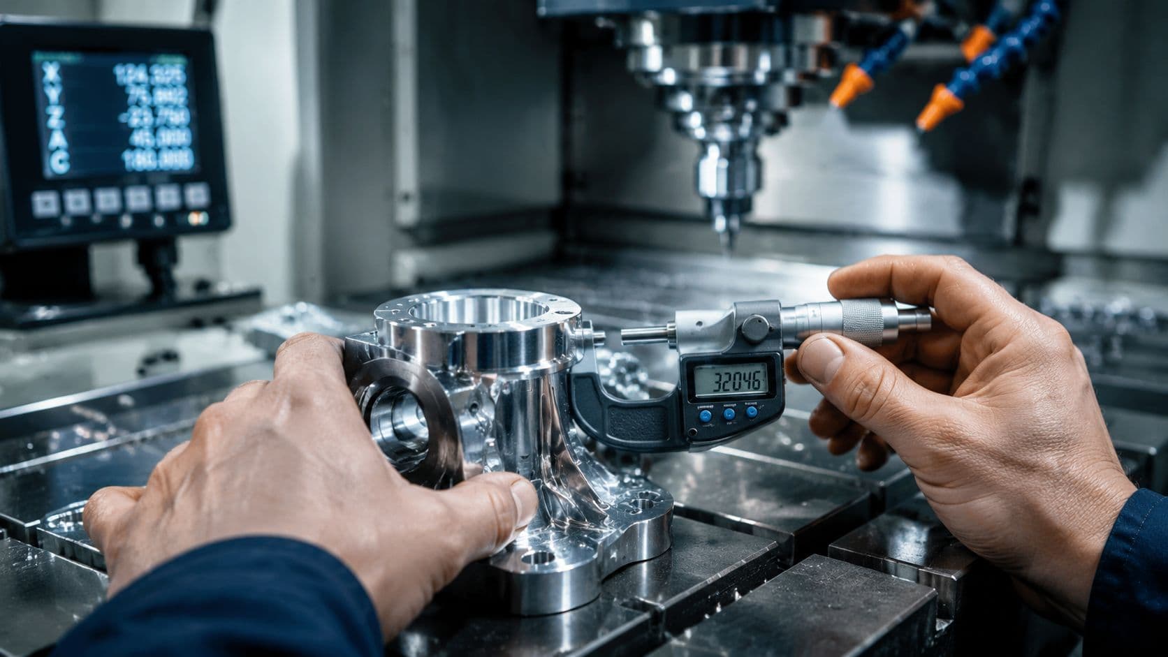
Most tight tolerance requests are over-specified before a cutter ever touches the part. In machining, ±0.005 in (±0.127 mm) is already the point where many shops stop treating a dimension as routine and start treating it as a cost decision, and once you push below that line, fixturing, thermal control, and inspection stop being optional supports and become part of the process itself (Modus Advanced). The practical question isn't whether a machine can move that precisely, it's whether the feature deserves the expense of holding it there.
Table of Contents
Achievable Tolerances by Process and Material- Reference table for realistic process capability
Choosing the Right Equipment for the Geometry- Equipment choice by feature type
Design for Manufacturability Rules That Actually Help- Tighten only the features that drive function
Tooling Fixturing and Shop Floor Discipline- What actually keeps the number alive
Inspection Methods and the True Cost of Precision- Pick the inspection method for the feature
A Recommended Workflow From CAD to Shipment- Build the handoff around process and verification
Tight Tolerance Checklist for Your Next Drawing
What Tight Tolerance Machining Means
A tight tolerance is a cost decision, not a quality trophy. It means a specific feature has to be controlled closely enough that the part still fits, functions, and repeats after real machining, with inspection and process discipline to match. The mistake is treating every dimension on the print that way, because the cost jumps quickly while the functional return often stays flat.

The numeric bands shops use
For general CNC work, a common baseline sits around ±0.010 in (±0.25 mm). Tight tolerance machining is usually taken to mean something tighter than about ±0.005 in (±0.127 mm) (Modus Advanced). In more demanding production work, many teams call ±0.002 in to ±0.001 in the precision zone, and aerospace often treats ±0.001 in or even ±0.0005 in as the level reserved for critical features.
Practical rule: if the dimension does not affect fit, function, sealing, alignment, or gaugeability, it usually does not belong in the tightest band on the drawing.
The meaning of those numbers changes by industry. General manufacturing may call ±0.002 in tight, while aerospace treats that as one step on the path toward precision control (Modus Advanced).
Why the number changes the process
Once tolerances move below ±0.005 in, the shop has to manage the part more aggressively. Fixturing has to hold position better, thermal variation has to stay under control, and inspection has to catch tool wear or setup error before the run drifts out of spec (Modus Advanced). That is why the better question is not how precise the machine can be, but what precision the feature needs so the assembly works and stays stable in use.
A more useful way to frame the problem is process capability, not just nominal dimensioning. Tight tolerance machining is about repeating the same result on the same feature, run after run, with enough evidence that the feature stays inside the band every time. Once that is clear, the next decision is more practical, which process chain can hold the number without wasting budget?
Achievable Tolerances by Process and Material
The quote should follow the process chain, not the other way around. A team that asks for a ±0.002 in bore in a part that will only ever see standard CNC and one rough setup is usually asking for a rescue, not a quote. The smarter move is to match the process to the feature, then let the material tell you how much margin you really have.
Reference table for realistic process capability
| Process Chain | Typical Tolerance | Typical Use Case |
|---|---|---|
| Standard CNC | about ±0.01 to ±0.02 mm | General prismatic parts, housings, non-critical features |
| Precision CNC | about ±0.005 to ±0.01 mm | Mechanical assemblies, tighter mating features |
| CNC plus reaming | about ±0.003 to ±0.008 mm | Holes that need better size control and repeatability |
| CNC plus grinding | about ±0.001 to ±0.005 mm | Press fits, bearing seats, alignment features |
The reason the numbers tighten is simple. Each added finishing or correction step removes geometric error, but it also adds cycle time and cost, so the shop only reserves those steps for features that require them (Rapid Protos). That's especially true on press fits, bearing seats, and alignment bores, where a loose process chain can make a technically acceptable print produce an unreliable assembly.
Material changes the tolerance window
Material matters because the same toolpath behaves differently in different stock. Metals with stable behavior are usually more forgiving than plastics and composites, while plastics need special care because of thermal expansion and moisture sensitivity (Epectec). Mixed-material assemblies can be even trickier, because a dimension that looks perfect at the machine can move after shipping, temperature change, or field use.
A tolerance that looks safe on paper can still fail in assembly if the material moves after machining.
The shop floor reality is that aluminum and brass tend to be easier to control than tougher steels or dimensionally sensitive plastics, but even “easy” materials need the right process chain when the feature is critical. If the part contains inserts, bonded elements, or dissimilar materials, the tolerance call has to account for the whole assembly, not just the machined pocket or boss. That's where the handoff from geometry to equipment choice starts to matter.
Choosing the Right Equipment for the Geometry
The machine doesn't earn its keep by sounding impressive. It earns its keep by removing setups, maintaining access to the feature, and keeping the part stable while the tolerances get smaller. That's why a 5-axis machine isn't automatically “more precise” than a 3-axis mill, it's often more precise because it can hold geometry in fewer setups, which reduces drift.

Equipment choice by feature type
A 3-axis mill is still the right answer for prismatic parts with straightforward access. A 4-axis or 5-axis platform becomes valuable when the feature set creates awkward re-clamping, compound angles, or undercuts that would otherwise force extra handling. For those cases, fewer setups usually matter more than any theoretical spindle advantage. If you want a deeper look at that setup reduction logic, the internal workflow at 5-axis CNC milling is worth comparing against a three-axis plan.
A CNC lathe belongs on cylindrical and rotationally symmetric parts, especially shafts, bushings, and bores that benefit from concentricity control. Wire EDM earns its premium on intricate 2D profiles and hardened materials, and the process can reach about ±0.0001 in or better on certain profiles under controlled conditions (GosCPM). Grinding sits in a similar premium category for mating surfaces and finish-critical features, with some high-precision CNC and grinding operations holding about ±0.0001 in (±0.0025 mm) under controlled conditions (GosCPM).
A quick heuristic for specifying the process
If the feature can be hit cleanly in one setup, start there. If it can't, choose the machine that removes the most setups, not the one with the longest feature list.
That rule keeps the quote tied to geometry instead of hype. It also prevents a common mistake, asking a general milling process to behave like a finishing process when the print really wants grinding, EDM, or a turning operation. In tight tolerance machining, the right equipment is the one that minimizes handling error at the feature level, not the one that just looks modern on the machine list.
Design for Manufacturability Rules That Actually Help
The drawing is where most precision budgets are won or lost. Teams often tighten every linear dimension because the number feels safer, then wonder why the supplier's quote jumps and the assembly still isn't better. The better approach is blunt, feature-by-feature discipline.

Tighten only the features that drive function
Start with the features that affect fit and function. Mating surfaces, bearing seats, alignment bores, gauge features, and press-fit diameters deserve the tightest tolerances because they control how the part behaves in assembly and service. Non-locating bosses, cosmetic edges, and internal clearances that aren't functional usually don't.
That rule sounds obvious, but it's where most overspecification lives. If a dimension does not move the assembly toward or away from failure, tightening it usually just raises inspection burden and setup risk. Buyers who want a clean cost model should use the same logic that machinists use on the floor, spend precision where it changes fit, save money where it doesn't.
Make the datums easy to inspect and hold
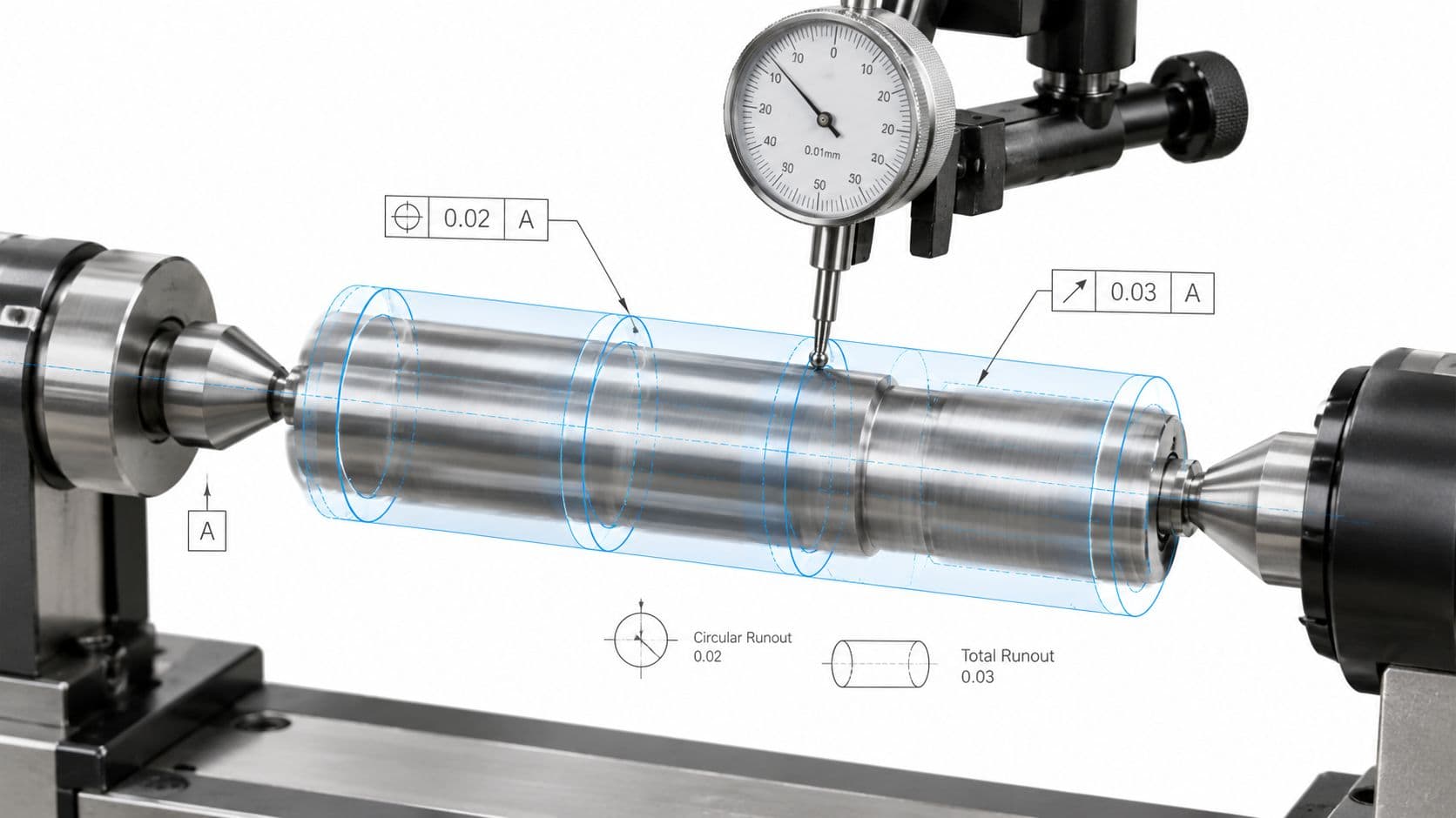
GD&T is useful when it clarifies location control, not when it creates a puzzle. Datums on the same side of the part, datum targets instead of whole-surfaces where appropriate, and MMC modifiers when the functional stack allows them all make location control more stable and easier to verify (Epectec). The reason is simple, the shop can only clamp and inspect what the drawing clearly defines.
If the datum scheme is vague, tight tolerance machining turns into a guessing game with a measurement report attached.
That's also why the part's rigidity matters. Tight machining alone won't rescue a weak datum strategy, poor clamping, or a thin wall that flexes under tool pressure. The same caution applies to plastics and mixed-material assemblies, where thermal movement and moisture uptake can change how the fit behaves after machining (Epectec).
For a broader design checklist, design for manufacturability is where to pressure-test the print before the quote goes out. The best tight tolerance parts are usually the ones that were designed to need fewer of them.
Tooling Fixturing and Shop Floor Discipline
A tolerance on paper is just a promise. The part only keeps it if the operator, setup, and machine all behave the same way from the first cut to the last inspection. That's why precision quotes should always be read as a process plan, not just a price.
What actually keeps the number alive
The first control point is workholding. Soft jaws, vacuum fixtures, and dedicated tooling plates reduce movement and improve repeatability, especially when the part has thin walls or few natural clamping surfaces. The second is tooling, because cutter grade, geometry, runout, and presetter offsets all feed directly into dimensional drift.
Thermal stability matters just as much. Machine warm-up, stable coolant control, and chip evacuation keep the toolpath from chasing changing conditions, while wear compensation helps the part stay within band as the tool ages. On a quoted precision job, I always want to know whether the supplier is planning to probe, compensate, and verify in-process, not just inspect at the end.
Practical rule: if the shop needs multiple re-fixtures to finish a critical feature, ask how they plan to prevent drift before approving the run.
That's where a single setup usually beats three. Even with the same spindle and controller, every extra clamping event adds a new chance for datum shift, part distortion, or tool path mismatch. In-process probing and tool-breakage detection matter more as tolerances tighten, because they catch errors before a batch turns into scrap.
The red flags are easy to spot. If the quote is unusually cheap for a feature that clearly needs controlled fixturing, or if the supplier can't explain how they'll hold the part in a stable condition, the “tight” tolerance probably isn't being priced correctly. Precision work is never just about cutting metal, it's about controlling the conditions around the cut.
Inspection Methods and the True Cost of Precision
Tight tolerance machining gets expensive the moment you have to prove the result. A supplier can promise precision all day, but without the right inspection chain, that claim does not carry much weight on a purchase order or in an NPI review. The proof method has to match the feature, and the method itself can become a hidden cost driver.

Pick the inspection method for the feature
Go/no-go gauges still earn their place on repeat features that need fast pass-fail checks. Optical comparators help when edge geometry or profile matters, while CMMs are now part of proving micron-class results rather than a luxury item in a lab. If you need a shop that can handle that level of verification, CMM inspection services are part of the process, not an afterthought. Laser and structured-light scanning are useful where the geometry is more complex and you need a fuller map of the surface, not just a few points.
Surface finish is separate from size, but it still changes how a fit behaves. If the finish matters to assembly, sealing, or sliding contact, the inspection plan should include the finish method too. SPC is useful on repeat jobs because it shows whether the process is drifting before a batch falls out of tolerance (GosCPM).
The cost curve gets steep fast
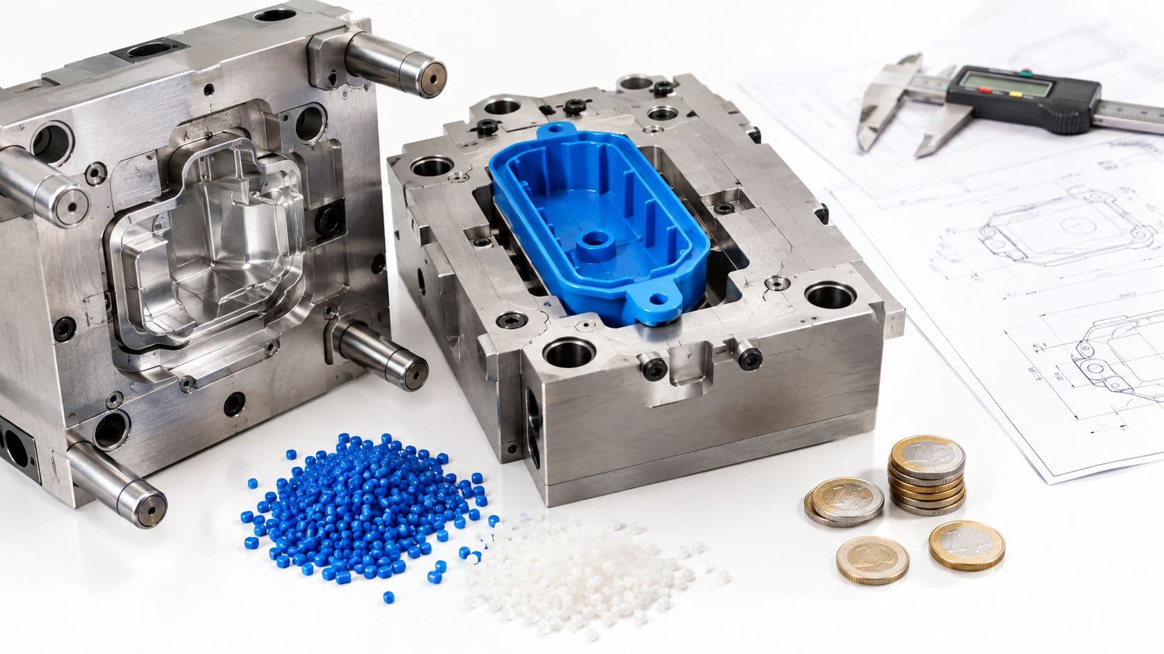
The commercial side is where many programs get surprised. One guide says moving from standard tolerances to ±0.005 in can raise cost 2-3x, tightening to ±0.002 in can raise it 4-6x, and ±0.001 in can reach 8-12x. Another guide says tightening from ±0.005 in to ±0.002 in can increase cost by 25-50% (Modus Advanced). The spread is not a contradiction, it shows that material, setup count, inspection burden, and geometry all change the price.
That is the point procurement teams need to hear during NPI and cost-down reviews. Precision is not free, and the inspection plan often shows why. If a drawing asks for tight tolerance on a feature that does not need it, the quote may be telling you the design needs a second look, not that the shop is overcharging.
A Recommended Workflow From CAD to Shipment
The easiest way to avoid costly back-and-forth is to move from file to process plan in one pass. Start by sending the supplier clean CAD in STEP, IGS, STL, SolidWorks, DXF/DWG, or PDF form, then ask for a DFM review before you freeze the print. That keeps the quote tied to the feature list, not to assumptions hidden in the model.
Build the handoff around process and verification
The next step is process confirmation. The supplier should identify whether the part belongs in 3-axis, 4-axis, or 5-axis CNC, turning, EDM, grinding, or a prototype-first route such as 3D printing or vacuum casting, depending on the geometry and quantity. For low-volume metal and plastic parts, a single supplier that can move from prototype to NPI to production reduces handoff risk and keeps the tolerance logic consistent from one build to the next.
Inspection should be specified with the same clarity as the process. If the part needs documented verification, the quote should show how the supplier will prove it, whether that means CMM, scanning, or another measurement plan. Surface finishing also needs to be tied to the functional requirement, because a cosmetic finish and a controlled Ra/Rz target are not the same thing.
Where outsourcing makes sense
A partner is useful when the project needs multiple processes under one roof, fast quoting, and dimensional control without a lot of supplier management overhead. LC Proto fits that profile for CNC machining, 3D printing, sheet metal, injection molding, vacuum casting, surface finishing, and documented inspection, and it's one option when the team wants low-to-mid volume parts moved from CAD to shipment with a single source. The practical value is workflow consolidation, not magic, especially when precision parts need a consistent inspection trail.
The right supplier doesn't just machine the part, it keeps the tolerance strategy intact from quote to shipment.
That's the standard to use on the next job. If the supplier can't explain the process chain, the inspection method, and the reason for each tight dimension, the project probably needs one more DFM pass before release.
Tight Tolerance Checklist for Your Next Drawing
The fastest way to make a drawing shop-ready is to treat every feature separately. Tight tolerance belongs on the dimensions that change fit, alignment, seal, or gaugeability. Everything else should stay at the loosest tolerance that still protects function.
| Feature Type | Recommended Tolerance Practice | Why It Matters |
|---|---|---|
| Mating surfaces | Tighten only to the level needed for fit | Controls assembly behavior |
| Bearing seats | Use the tightest practical process chain | Protects rotation and retention |
| Alignment bores | Define clear datums and inspect directly | Keeps location control stable |
| Press fits | Match tolerance to the actual process capability | Reduces assembly surprises |
| Cosmetic edges | Keep standard tolerances | Avoids paying for non-functional precision |
| Mixed-material interfaces | Account for movement and environmental effects | Prevents false precision |
A useful rule of thumb is simple. If a feature will never be measured in a critical inspection or used as a functional interface, it probably doesn't need a tight callout. If it does, make the datum scheme and inspection method explicit so the shop can prove the result without improvising.
FAQ
How do you choose between ±0.005 in and ±0.002 in?Use ±0.005 in for features that matter but don't demand the tightest process control, then move to ±0.002 in only when the feature directly drives fit, alignment, or another critical function. The decision should follow assembly risk, not habit.
Does tighter tolerance always improve assembly fit?No. If the datum strategy, fixturing, or material behavior is weak, tighter machining can create more rejects without improving the actual assembly.
When is a partner like LC Proto the right call?When the job needs process flexibility, documented inspection, and a path from prototype to low-to-mid volume production without resetting the tolerance strategy at each handoff.
If you need tight tolerance machining for a new prototype or a low-volume production run, send your CAD to LC Proto and ask for a DFM review before you release the drawing. That's the fastest way to find out which dimensions deserve precision and which ones are just adding cost.