Prototype Sheet Metal Fabrication: A 2026 Guide For
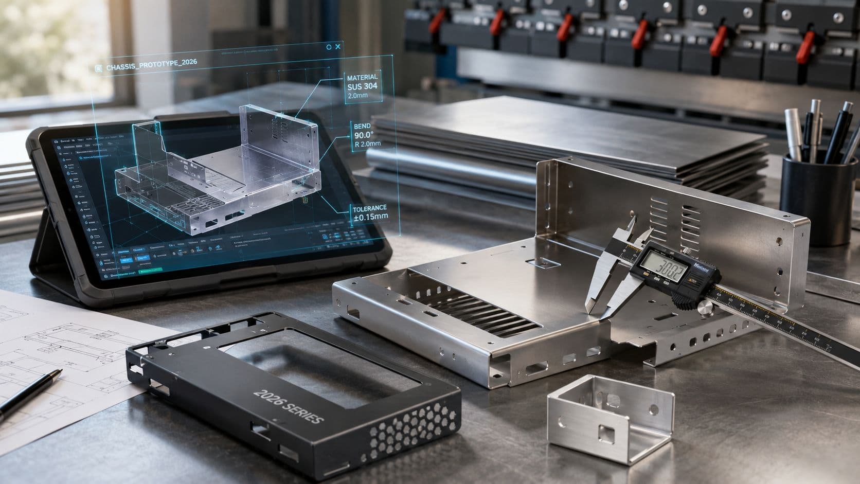
You've got the drawing frozen, procurement wants a quote, and the prototype build is waiting on parts that don't exist yet. The chassis has to fit the battery pack, the bezel has to survive coating, and the bracket has to prove it won't twist when the hand unit gets dropped on a bench. That's the exact moment prototype sheet metal fabrication stops being a generic shop service and becomes a design decision about what to validate now, what to defer, and how much rework you can afford if you guess wrong.
Table of Contents
Choosing the Right Process Mix for Your Prototype- Forming and joining should follow the part's job
Selecting Material, Thickness, and Finish for the Job- Thickness should match the load, not the ego
Applying DFM Rules That Prevent Costly Rework- The bend and feature rules that matter most
Preparing CAD and CAM Files That Quote Cleanly- What a clean submission package looks like
Prototyping Versus Low-Volume Production Trade-Offs- Where the economics actually turn
Inspection, QA, and Your Supplier Checklist- What to check before you accept the parts
What Prototype Sheet Metal Fabrication Really Means in 2026
A good prototype starts with a hard question, not a shop order. If you're trying to validate a 304 stainless chassis, a powder-coated bezel, and a bent aluminum bracket for a rugged handheld, you're not buying “metal parts,” you're buying evidence. The prototype needs to prove fit, form, joining, coating, and assembly behavior before the box build gets locked.
That's why prototype sheet metal fabrication sits between a one-off bracket and a production release. An engineering prototype is there to test geometry, bend behavior, hole alignment, and service access. A pre-production prototype is closer to the final state, so tolerances, finish, and documentation matter more because the team is trying to confirm that the process itself can scale without surprises.
The market context matters too. One U.S. industry report put 2024 industry sales at $34.2 billion, with the sector growing at 3.9% annually over the prior three years worldmetrics.org sheet metal fabrication statistics. The same source says 45% of companies used additive manufacturing for prototyping sheet metal components in 2023 worldmetrics.org sheet metal fabrication statistics. That combination tells you prototype work now lives in a hybrid workflow, where printed fixtures, fit-check aids, and companion parts are normal validation tools.
What changes in 2026
The practical reality in shops is speed, not theory. Fiber lasers around 6 kW are now standard equipment in many prototype environments, and quick-turn stock programs have made common gauges feel almost immediate in some regions. Prototype lead times are often measured in business days, not weeks, which changes how aggressively you can iterate industrial design details before NPI.
Practical rule: If a design choice can still be challenged without breaking the assembly schedule, prototype stage is the cheapest place to do it.
The point of the prototype is not to preserve every production assumption. It's to challenge the assumptions that are still soft, while keeping the ones that really define the product.
Choosing the Right Process Mix for Your Prototype
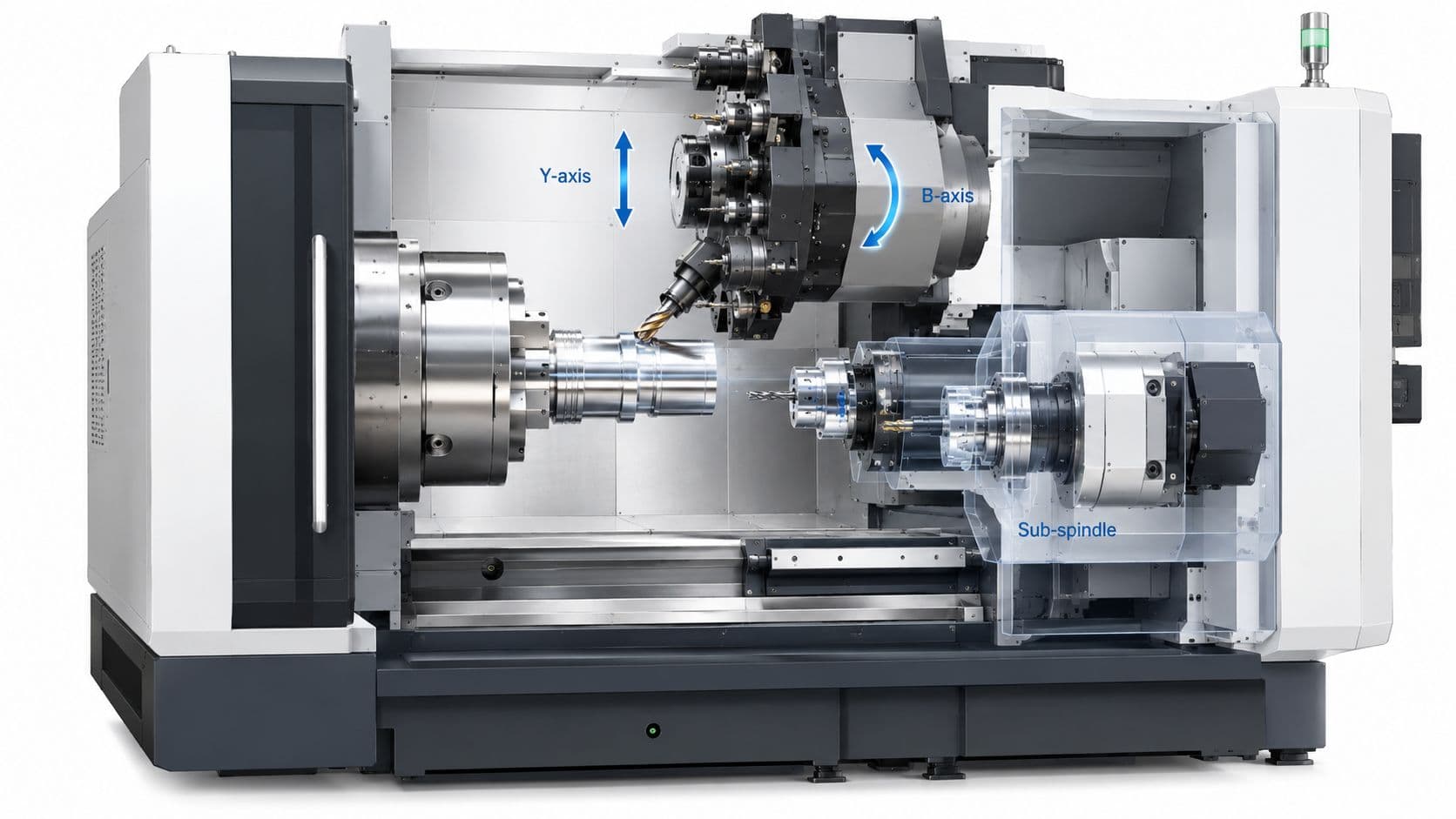
Start with the cut process, because it sets the tone for everything downstream. For most flat parts, laser cutting is the default choice for 2D features on sheet stock up to about 6 mm mild steel or 4 mm stainless. It's fast, it's repeatable, and it gives you the cleanest route into a bend-and-assemble workflow when the geometry is still fluid.
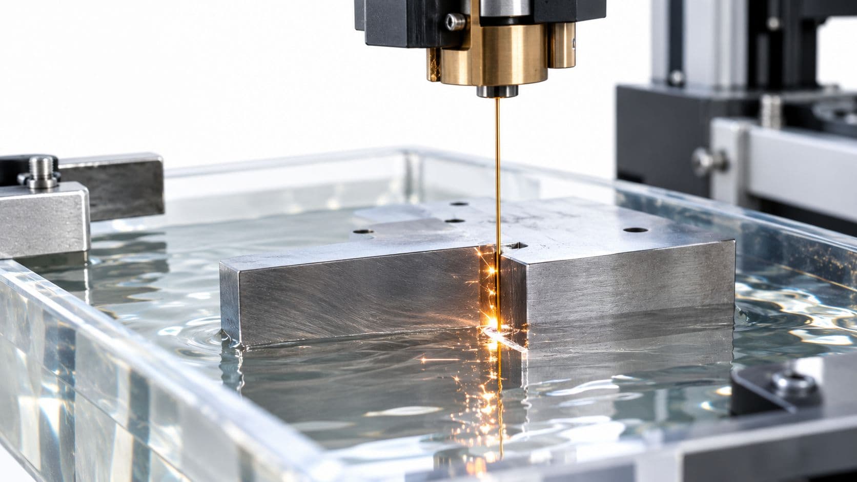
Waterjet earns its place when heat matters more than speed, or when you're working with thicker stock and want to avoid heat-affected distortion. Plasma has a place too, but not on parts where cosmetic cut quality or tight edge condition is critical. If the prototype needs a burr-free edge and stable feature geometry, laser usually wins the first round.
Forming and joining should follow the part's job
Press brake selection should match the part, not the other way around. Small, thin prototypes can be handled on 20 to 50 ton pneumatic brakes, which are useful for sub-1 mm work and quick adjustment cycles. Structural parts that need more angular consistency are better handled on 100+ ton hydraulic brakes, especially when the flange geometry starts to matter.
Joining is where many prototype programs lose time. TIG is the usual choice for stainless cosmetic work because the bead can be controlled more tightly. MIG is faster for mild steel brackets. Spot welding works well on thin sheet stacks. Robotic welding usually doesn't make sense unless the quantity or repeatability justifies the setup burden.
Finishing should be treated as a functional decision, not decoration. Deburring and bead blasting are common cleanup steps. Powder coating helps when corrosion resistance and appearance both matter. Anodizing is the normal finish path for aluminum cosmetics. Electropolishing is useful when stainless needs a cleaner surface condition, but it also adds process complexity.
The three examples below show how the mix changes with the job.
| Part Type | Typical Gauge | Cut Process | Form/Join | Finish |
|---|---|---|---|---|
| 1.2 mm cold-rolled steel bracket | 1.2 mm | Laser | Brake form, MIG or fasteners | Deburr, powder coat |
| 2 mm 5052 aluminum enclosure | 2 mm | Laser or waterjet if heat is sensitive | Brake form, rivets or fasteners | Deburr, anodize or paint |
| 3 mm 304 stainless cover | 3 mm | Laser | Brake form, TIG or hardware | Deburr, bead blast or electropolish |
The most efficient prototype path is usually the least fancy one that still answers the engineering question. For shops that publish precision cutting capability, a useful reference is this laser cutting precision overview.
Selecting Material, Thickness, and Finish for the Job
Material choice should come from the part's function, not a habit or a material chart someone saved two projects ago. Cold-rolled steel is the default prototype material because it's stocked in common gauges, it welds cleanly, and it behaves predictably in the press brake. For a lot of brackets and panels, that's exactly what you want when the first goal is fit verification, not final appearance.
5052 aluminum is the better choice when the part needs corrosion resistance and easier forming, especially for enclosures with repeated bend features. 6061 aluminum makes more sense when the part will need post-bend machining or added structural stiffness. 304 stainless belongs on the shortlist only when corrosion or cosmetic requirements really justify the extra forming difficulty and cost pressure.
Thickness should match the load, not the ego
Thin sheet is not a virtue on its own. For cosmetic panels with captive fasteners, 0.9 to 1.2 mm is usually enough. Brackets that carry modest load often sit in the 1.5 to 2 mm range. Chassis and load-bearing frames usually need 2.5 to 3 mm so the prototype behaves like the part instead of a warped stand-in.
Stainless can look deceptively simple on a drawing and still fight you on the brake. Once the gauge goes up, the bend radius and springback assumptions matter much more than the CAD model suggests.
There are a few common traps. 304 stainless work-hardens fast, so aggressive bends above 2 mm need more generous inside radii. Galvanized G90 can create trouble in tight-tolerance prototypes because the zinc layer can shift hole positions and complicate fit. If you need a coating, pick the coating for the part's use case, not because it sounds production-like.
Finish should still map to the job. Powder coat fits outdoor enclosures and rugged electronics. Anodizing fits aluminum cosmetics. Bead blasting before paint helps adhesion. Plating is usually a poor default for prototypes unless you're actively validating a vendor or a corrosion process.
The quick decision rule is simple. Choose the material that best reproduces the mechanical behavior with the least amount of process friction, then add finish only when it affects function, fit, or customer-facing appearance.
Applying DFM Rules That Prevent Costly Rework
DFM isn't a style guide. It's a way to keep the prototype from teaching you the wrong lesson. The most useful rules are the ones that match actual process capability, because a prototype that ignores bend physics or feature spacing usually comes back with revised holes, reworked flanges, or a second setup.
The bend and feature rules that matter most
A workable starting point is minimum flange length at about 3× material thickness plus bend radius. For mild steel and aluminum, the inside bend radius is often tied closely to the material thickness. Hole-to-edge distances should stay at least 1.5× thickness to reduce distortion. Those are not aesthetic preferences, they're the line between a clean first article and a part that needs hand correction.
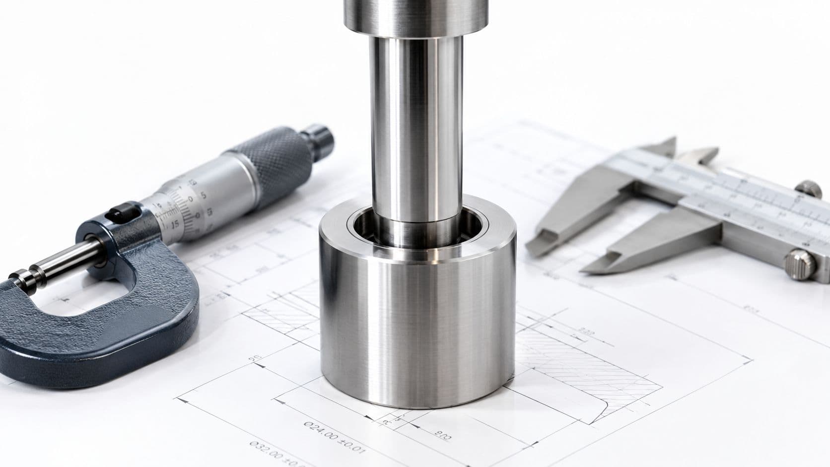
K-factor and bend allowance should be treated as live values, not fixed CAD defaults. The fabrication reference linked in the brief notes common practical benchmarks around ±0.508 mm (±0.020 in) for forming or bending, ±0.254 mm (±0.010 in) for bend-to-hole or feature relationships, ±1° for bend angle, and ±0.127 mm (±0.005 in) for holes approved sheet metal DFM design reference guide. That spread matters because a prototype drawing should only carry tight callouts where they protect the interface.
Keep the tolerance budget for the features that touch other parts. Don't spend it on raw edges, cosmetic corners, or surfaces nobody measures.
Laser-cut features need the same discipline. Use a 1:1 width-to-gap rule for slots when possible, and don't stack notches near a bend unless you're deliberately making room for a forming feature. Sharp internal corners are still a classic failure point because they concentrate stress and complicate the cut path. Thin tabs also tend to distort or bend when they're too close to a forming line.
| Feature | Laser cut ≤3 mm | Laser cut 3–6 mm | Bend / form | Weldment |
|---|---|---|---|---|
| Hole position | Tight only on functional interfaces | Check for heat and feature distortion | Verify after forming, not before | Confirm fit after weld shrinkage |
| Slot width | Hold conservative clearances | Expect more edge variation | Avoid near bends when possible | Confirm post-weld access |
| Edge distance | Keep generous spacing | Use extra margin near heavy sections | Increase for flange-driven distortion | Watch for heat and clamp marks |
| Internal corner | Prefer relief and radius | Avoid sharp geometry | Prevent tear points at folds | Check weld access and cleanup |
For a deeper process lens on manufacturability choices, the DFM guide from FIRMFG is a useful companion.
Preparing CAD and CAM Files That Quote Cleanly
A shop can't quote what it can't read. Clean file prep starts with a model that already knows the bend table, the sheet thickness, and the actual K-factor used by the fabricator. If your flat pattern is built on a generic CAD default, you're asking the shop to reverse-engineer your intent before they even open the part.

What a clean submission package looks like
Use a bent-state STEP file and a flat DXF. Keep the units explicit, because mixed-team builds still go wrong on inches versus millimeters. Put bend lines on the centerline layer, and make sure the flat pattern reflects the actual unfolded thickness rather than a generic sheet assumption.
A good package usually includes:
- Drawing: Shows critical dimensions, revision letter, and any finish notes.
- Flat DXF: Gives the laser or punch operator the exact cut geometry.
- 3D STEP: Lets the programmer confirm formed-state intent.
- BOM: Helps with fasteners, inserts, and welded hardware.
- Revision letter: Prevents old files from sneaking into the queue.
CAM-side mistakes are usually boring and expensive. Engraving layers get imported as cut paths. Mirrored bodies create duplicate closed profiles. Revision marks drift between drawing and model. Each one slows a quote cycle because someone has to stop, ask, and reconcile the files before metal gets touched.
A clean package doesn't just save the shop time. It protects your own schedule from avoidable RFQ back-and-forth.
The number to keep in mind is simple. Every missing item in the submission package can add 1 to 3 days to the prototype quote cycle, because the shop has to clarify geometry, revision status, or bend intent before pricing the job. If your program is on a four-week clock, that delay is not small.
Prototyping Versus Low-Volume Production Trade-Offs
Prototype and low-volume builds solve different problems, and you can feel the difference in tooling, timing, cost, and inspection depth. Prototype work is about uncertainty. Low-volume production is about controlling a process that's already been proven. Mixing those goals usually creates the wrong quote and the wrong expectation.
Where the economics actually turn
As a rule of thumb, prototypes usually make sense up to about 10 to 25 parts before tooling amortization starts pushing the economics toward a different build strategy. Soft tooling can stretch that window if you're using laser-cut weldments or 3D-printed forming aids, but it doesn't erase the crossover. Prototype shops often accept 1 to 10 parts with setup amortized into the job, while low-volume runs tend to live in the 50 to 500 part range with harder tooling and longer planning horizons.
Inspection changes too. Prototype jobs usually lean on first-article dimensional checks and functional fit-up. Low-volume programs add more formal sampling, weld procedure qualification, and incoming material certificates. That's not bureaucracy for its own sake, it's what a team needs once the design stops changing every week.
| Axis | Prototyping | Low-Volume Production |
|---|---|---|
| Tooling investment | Minimal, soft tooling only | Moderate hard tooling amortized |
| Lead time | Fast first parts, usually days | Longer setup, then more stable release |
| Per-part cost | Higher because setup is spread over few parts | Lower through batch economy |
| Inspection depth | First-article and fit-focused | Sampled and documentation-heavy |
The crossover rule is practical. If the geometry is unproven, stay in prototype. If only fit is unproven, jump sooner to low-volume. If the supply chain is unproven, do both sequentially so you don't confuse part risk with vendor risk.
For teams wanting a side-by-side vendor comparison on quick-turn versus bridge builds, FIRMFG also supports prototype and low-volume sheet metal workflows as part of a broader rapid manufacturing setup, which can help when the geometry and the schedule are both moving targets.

Inspection, QA, and Your Supplier Checklist
The prototype is not done when the last bend comes off the brake. It's done when the part survives inspection, mates to the assembly, and gives you confidence about the next revision. That means QA has to cover more than a caliper check, especially once coating, welding, and inserted hardware enter the build.
What to check before you accept the parts
Use calipers on critical edges and hole centers, and bring in CMM measurement when the profile gets complex or the tolerance stack matters. Check burrs, weld spatter, coating defects, and any distortion around formed edges. Then fit the part against the mating assembly, because a perfect flat-pattern measurement can still fail once it touches real hardware.
The published guidance in the brief points to a useful discipline for this stage, with benchmark tolerances that separate general forming accuracy from tighter feature-level control springer experimental work on sheet metal bending. That matters because bend outcome depends on process variables that have to be established on industrial machines, not assumed from simulation alone.
A supplier quote should answer a few basic questions up front:
- Material traceability: Ask for mill certs and grade confirmation.
- Revision control: Make sure the quote ties to one revision letter only.
- Weld process clarity: Confirm whether TIG, MIG, or spot welding is being used.
- Finish sample visibility: Request a visual sample or finish standard when appearance matters.
- Lead-time commitment: Build in a realistic buffer for clarification and rework.
For teams that need tighter dimensional accountability, the CMM inspection services overview is worth reviewing before you release a critical prototype.
When to escalate the supplier
A job shop is fine when the part is simple and the risk is mostly geometric. Move to a certified prototype supplier when the assembly carries cosmetic requirements, welded subassemblies, or tight functional interfaces that affect the rest of the product. If the enclosure also has PCB clearance, connector alignment, cable routing, airflow, grounding, EMI continuity, or service access concerns, that's a sign the prototype is validating a system, not a sheet metal shape.

Every checkpoint protects either your schedule or your design intent, and skipping one usually costs you both. Treat the prototype as a controlled argument with the design, not a rubber stamp for it.
If you need a partner that can handle rapid sheet metal prototypes, DFM feedback, and the handoff from early validation to low-volume build work, take a look at FIRMFG. Their sheet metal workflow fits the exact problems covered here, from enclosure fit checks to short-run validation, and it's worth sending a file when you need a fast, practical quote.