Prototype CNC Milling Explained: Materials and Tolerances
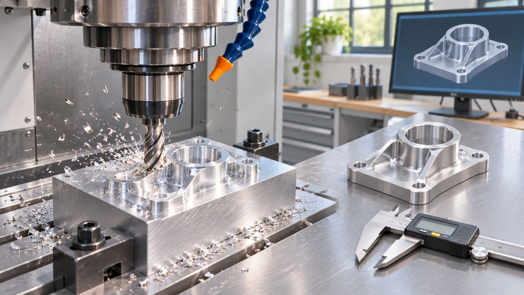
The bracket looks simple on screen. Two bores, a pocket, a mounting face, and a tolerance block that reads like boilerplate. Then the quote comes back with a lead time longer than your sprint and a line item for material you didn't expect.
You need two answers fast. Which of those tolerances does your test depend on, and where are the days going?
Both come from the same discipline. Prototype CNC milling is subtractive, so every feature you draw has to be reachable by a cutter that needs clearance, and every tight dimension has to be measured by a person before the part ships. Connect each callout to the test it serves and each day of the schedule to the stage that consumes it, and the quote stops being a black box.
What follows is the process in order, the materials that make sense, the tolerances that earn their cost, and the honest reasons to choose a different process.
Table of Contents
- How CNC Milling Turns a CAD File into a Part
- Materials Prototype Milling Handles Best
Reading a row of the table
The two matching rules
Shapes and Features CNC Milling Handles Well- Where milling runs out of room
Design Choices That Cut Cost and Rework- Datums decide how many setups you pay for
Tolerances Worth Specifying and Those to Relax- The decision rule
Lead Times and Where the Schedule Really Goes
Milling Versus 3D Printing and Casting for Prototypes- What the energy numbers actually compare
Build a Tolerance Plan Before You Request a Quote
How CNC Milling Turns a CAD File into a Part
Prototype CNC milling is a subtractive process. A rotating cutter removes material from a solid block, called a billet, following toolpaths generated from a CAD model, with the machine's motion driven by a program rather than by a machinist's hands.
The principle is older than the software. Programmable machine tools became strategically important because factories needed repeatable processes that didn't depend entirely on operator skill, and the industrial base was already vast when the idea arrived. The 1952 Census Bureau statistical compendium recorded nearly 250,000 manufacturing establishments, with large plants accounting for about two-thirds of manufacturing employment. The same logic applies today, except the program now comes from a STEP file in an afternoon.
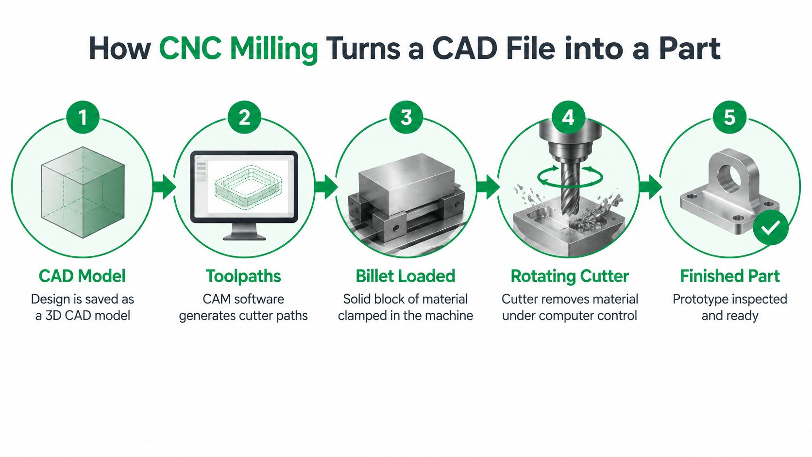
Here's the sequence, and the reason behind each step.
- Export a clean solid. Save a STEP file and confirm the body is closed and watertight. CAM software offsets surfaces to build toolpaths, so a gap or a stray surface produces a path that cuts air or dives into the fixture.
- Size the billet with allowance. Choose the grade first, then the stock. Leave a few millimeters on every face that will be machined and enough on top to clear the deepest pocket. An undersized block limits every operation that follows.
- Clamp it and set the datum. The datum is the zero point every dimension is measured from. Put it on a face that survives the first operation, because you'll re-use it for the second setup and for inspection.
- Generate toolpaths in two stages. Roughing passes clear bulk with a large cutter at aggressive parameters. Finishing passes hold the final surface with a smaller tool at conservative ones. Separating them lets you remove metal fast without risking the wall you just finished.
- Cut a first article and check it. Measure the critical features against the drawing before running the rest. A bore that's 0.05 mm under tells you to adjust tool compensation, not to scrap a batch.
- Deburr, finish and inspect. Sharp edges come off by hand or in a tumbler, then the part goes for anodizing, passivation or bead blasting, and back to inspection for a final dimensional record.
Because the model is digital, a revised design can be re-cut without new tooling. That's the practical reason milling fits iterative development: change the file, regenerate the paths, and run version seven tomorrow.
Materials Prototype Milling Handles Best
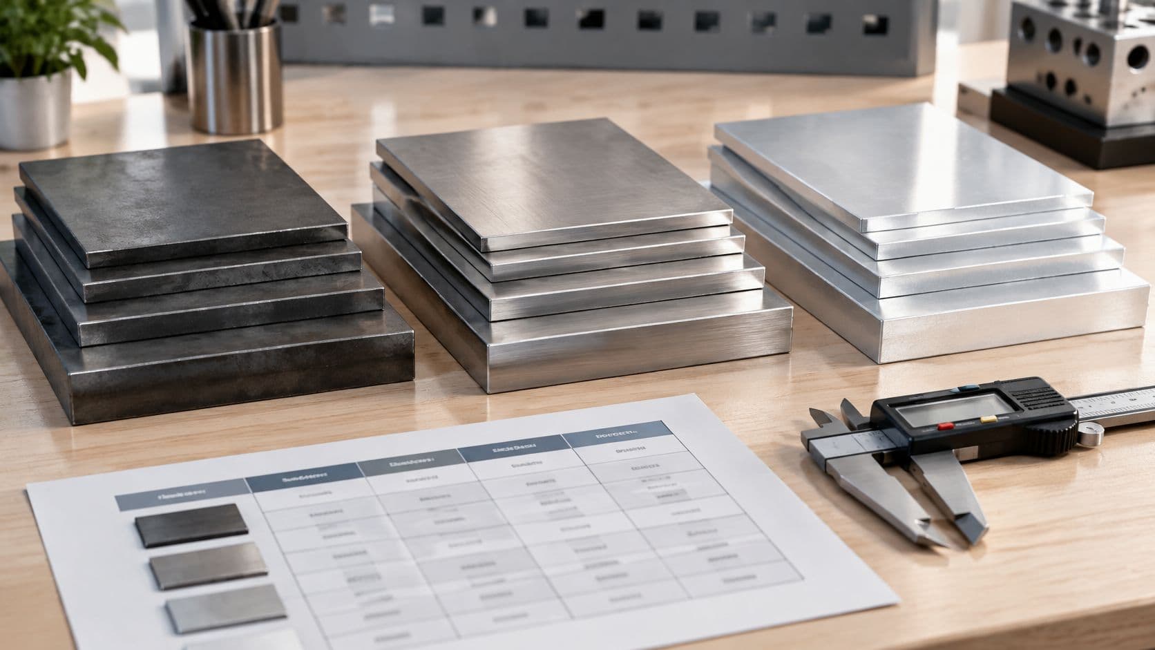
Material choice is a test decision, not a taste decision. Use the table as a lookup, then read the row against what your prototype has to prove.
Prototype materials by machinability and use
| Material | Typical prototype use | Machinability | Watch for |
|---|---|---|---|
| Aluminum 6061 | Enclosures, brackets, housings | Excellent, fast cutting | Soft; can gall if feeds are too low |
| Aluminum 7075 | High-load parts, aerospace-style structures | Good, harder than 6061 | Costlier stock; faster tool wear |
| Brass | Fittings, connectors, electrical parts | Excellent, clean chips | Heavy; higher stock cost than aluminum |
| Titanium Ti-6Al-4V | Lightweight high-strength parts | Difficult; low thermal conductivity | Slow cutting, high cost |
| Acetal (POM) | Gears, bushings, sliding parts | Very good, dimensionally stable | Low stiffness; watch heat buildup |
| Polycarbonate | Clear covers, light-duty housings | Good with sharp tools | Melts if speed is too high; internal stress |
| ABS | Visual models, snap-fit tests | Good | Surface finish needs careful tool choice |
Reading a row of the table
The machinability column predicts cycle time and therefore price. The watch-for column predicts the failure you'll be arguing about at the review. Aluminum 6061 cuts so freely that a cautious machinist running light feeds can work-harden and gall the surface, so the fix is a heavier chip load, not a slower one. Austenitic stainless does the opposite: it work-hardens under a dull tool, and every extra pass makes the next one harder on the cutter.
Titanium punishes heat. It conducts poorly, so the tool tip stays hot while the bulk of the part stays cool, and tools fail at the edge rather than the shank. That's why titanium prototypes cost more than the stock price suggests.
The two matching rules
Match the final material when the prototype must prove strength, heat or chemical behavior. A bracket that must survive a vibration table or a salt-spray cabinet is only evidence if it's the same alloy as production. A stand-in tells you about geometry, nothing else.
Use a machinable stand-in when only fit and appearance are being checked. For a housing that will be molded in glass-filled nylon, machining acetal or ABS gives you the interface checks at a fraction of the cost. For aluminum work, the practical detail matters: read the guide to machining aluminum prototype parts before you settle on a grade and finish.
One habit saves rework. Confirm the exact grade and temper with your supplier before drawing release, because 6061-T6 and 6061-T651 machine differently and behave differently under load.
Shapes and Features CNC Milling Handles Well
The strength of milling for prototypes is that the part is cut from solid stock. A bore, a thread, a bearing seat and a machined face all behave in test the way they'll behave in production, because there's no layer direction and no binder holding the material together.
Shapes that come cheap:
- Flat faces and simple contours, because a face mill covers area fast and leaves a reference surface for everything else.
- Pockets and slots with open corners, which a standard end mill can rough and finish without special tooling.
- Through holes and moderate blind holes, drilled and then reamed or bored if the diameter needs to be exact.
- Multi-sided parts that can be reached in a single 3-axis setup, which is the cheapest class of work you can buy.
- Undercuts and side features on a 4-axis machine, where a rotary table indexes the part instead of a second fixture.
- Compound angles and sculpted surfaces on a 5-axis machine, cut in one setup so repositioning error never enters the stack.
Where milling runs out of room
- Sharp internal corners. A round cutter leaves a radius. A 0.5 mm corner needs a 1 mm tool, which is slow and fragile.
- Very thin walls. Below roughly a millimeter in metal, the wall deflects away from the cutter, chatters, and springs back oversize.
- Deep, narrow pockets. Long, slender tools have to run slowly, and the depth you can reach is limited by the tool's length-to-diameter ratio.
- Features needing access from several directions. Each extra orientation is another setup, another datum transfer, and more chance for stack-up error.
A checklist to sort features before you commit
| Keep in the milled prototype | Move to a printed or cast part first |
|---|---|
| Bearing bores, dowel holes, sealing faces | Internal channels and conformal cooling paths |
| Threads and machined mounting faces | Deep ribs and lattice structures |
| Datum and interface surfaces | Sharp internal corners under 1 mm |
| Anything tested under real load or heat | Enclosures where only the outer shell is being reviewed |
Design Choices That Cut Cost and Rework
Most of the money in a milled prototype is spent or saved on the drawing, before a cutter touches metal. The single most expensive habit is drawing a sharp internal corner in a pocket.
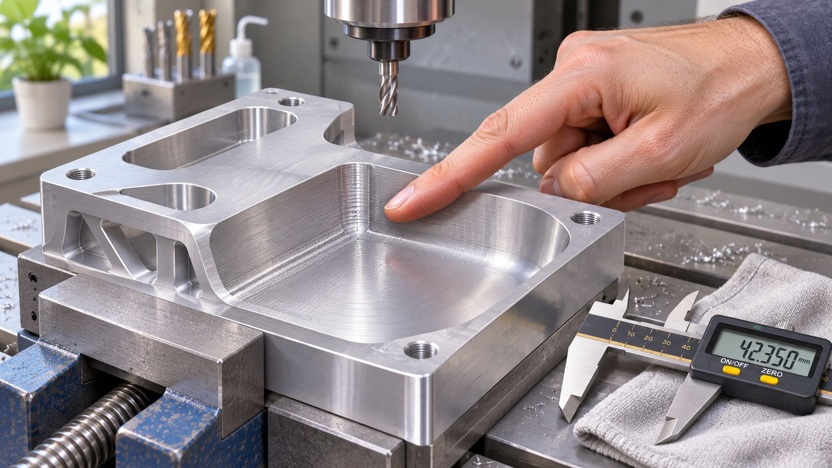
A corner radius smaller than the standard tool forces either a smaller cutter, which runs slowly and breaks easily, or a second operation such as EDM. Round the corner to a common tool diameter and the same pocket gets cut at full speed in one pass. Bigger radii are faster, not just cheaper.
Four more rules with their cost logic:
- Keep pocket depth reasonable against width. Past roughly four times the cutter diameter, the tool has to be long and slender, so feed rates drop and chatter risk climbs.
- Hold walls above about 1 mm in metal and thicker in plastics. A wall that deflects gets cut oversize, then scrapped or reworked.
- Use standard drill sizes and modest depth-to-diameter ratios. A nonstandard hole means a special tool or a slower helical milling path, and both show up on the invoice.
- Engrave shallow and wide. Depth is free only until the tool tip is too fine to survive the cut; a 0.3 mm deep engraving with a 0.5 mm tip is more legible and more reliable than a needle scratch.
Datums decide how many setups you pay for
Place datums on faces that will be used both for setup and for measurement. A datum on a raw cast surface or a rough sawn end is a datum you can't trust on the second operation, and that's how one extra setup becomes three. For a deeper breakdown of where the money goes, this explanation of what drives CNC milling cost is worth reading before you finalize the print.
Ask for manufacturability feedback before release. A machinist reading the drawing can flag the corner that needs a smaller tool, the hole that breaks into a pocket wall, and the face that has no clean reference, all before any chips are made. Fixing those on screen costs an email.
What I'd change first on most prototype prints: the four sharp corners in the main pocket. Radius them to the cutter diameter and you'll usually drop both cycle time and a finishing operation.
Tolerances Worth Specifying and Those to Relax
A drawing with no tolerance callouts still has tolerances. ISO 2768-1 supplies general linear limits in four classes, fine (f), medium (m), coarse (c) and very coarse (v), and a shop will machine to the class you name or to medium by default.
ISO 2768-1 general linear tolerances
| Nominal dimension (mm) | f (fine) | m (medium) | v (very coarse) |
|---|---|---|---|
| Over 3 up to 6 | ±0.05 | ±0.1 | ±0.5 |
| Over 6 up to 30 | ±0.1 | ±0.2 | ±1 |
Dimensions under 0.5 mm fall outside the general table entirely. Those need a custom tolerance written on the drawing, because there's no default for the machinist to fall back on.
The decision rule
Tighten only the features that mate with another part or carry load. Bearing seats, dowel holes, sealing faces and thread pitch diameters are the usual list. Everything else, including cosmetic surfaces, clearance holes and overall envelope dimensions, can sit on the general class without any effect on the test.
The cost difference is not small. Guidance on prototype machining reports that tightening from about ±0.1 mm to ±0.01 mm can raise cost three to four times (prototype machining guidance). That premium buys slower passes, more inspection, and sometimes a second finishing cut. Spend it where a fit or a seal depends on it, and nowhere else.
Practical rule: if you can't name the test that fails when a dimension drifts, that dimension belongs on the general class.
Prove each tight tolerance with the right inspection
A tolerance nobody measures is a wish. Match the method to the feature, and write the method on the drawing so the quote includes it:
- Coordinate measuring machine for positions, bore diameters and any feature tied to a datum scheme. It's the only practical way to prove a positional callout.
- Go/no-go gauges for holes checked in quantity, fast and unambiguous once the gauge is made.
- Micrometers and calipers for general external sizes and lengths, adequate for anything on the general class.
- Surface plate and height gauge for flatness and step heights, cheap and repeatable in skilled hands.
The tolerances themselves are only half the specification, so it's worth working through a full CNC machining tolerances reference when you set up a drawing template. A visual prototype machined to functional precision is money spent proving nothing.
Lead Times and Where the Schedule Really Goes
The quote says nine days, and it's natural to assume the spindle is turning for nine days. It isn't. Machining is usually a minority of the calendar, and the queue behind material and finishing is what you're waiting on.
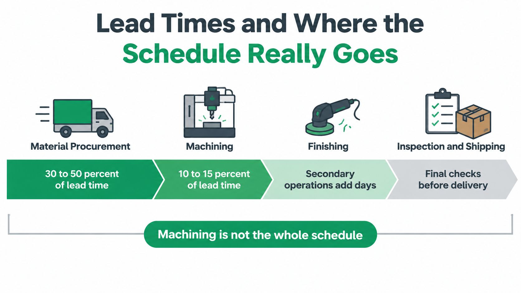
Walk the stages in order and note what you control at each one.
- Quote and design review. A complete drawing with datums, finish and quantity comes back accurate. A partial one triggers a revision loop. Every clarification email adds a day.
- Material procurement. This is usually the largest single block, and it's where grade choices bite. A common alloy in a stock size ships from a shelf; a mill run in an unusual temper takes a week or more.
- Programming and fixturing. Soft jaws, a fixture plate, CAM paths. Standard shapes reuse existing workholding; a part that needs a custom fixture pays for it here.
- Machining. The part everyone pictures, and the shortest stage in most jobs.
- Finishing. Anodizing, plating and passivation are usually sent out, and they run on their own schedule with their own minimum batch days. Decide the finish before the first cut so the part doesn't sit waiting for a decision.
- Inspection and shipping. Dimensional records, packaging and freight. A CMM report adds a step that a visual check doesn't.
The machining stage itself is getting faster. A 2018 study in the Journal of Computational Design and Engineering built a system for optimizing feed rates and reported that machine time could be reduced by 26% without tool breakage or chipping. That matters for iteration count, not for the material on order.
When you request a quote, ask for the schedule broken down by stage. A supplier who answers with a single machining day count is telling you they haven't thought about the rest.
Milling Versus 3D Printing and Casting for Prototypes
Milling isn't a niche route chosen by traditionalists. Dataintelo's on-demand CNC machining report puts CNC milling at 62.0% of global on-demand CNC machining revenue in 2025, with prototyping at 46.0%. The reason is simple: it's the only one of the three common routes that gives you production material properties and a verifiable bore in the same part.
Milling, printing and casting for prototypes
| Criterion | CNC milling | 3D printing (SLA, SLS, FDM) | Vacuum casting |
|---|---|---|---|
| Material realism | Production-grade metals and plastics | Resins and polymers; metal options vary | Polyurethane resins that imitate engineering plastics |
| Strength and heat | Full material properties | Varies; FDM parts are weaker across layers | Limited by the resin chosen |
| Tolerance on bores and faces | Tight and verifiable | Coarser; shrink and warp risk | Moderate |
| Surface finish | Good; finish can be machined | Smooth in SLA; visible layers in FDM | Good cosmetic finish |
| Small-batch replication | Few parts with real properties | One-offs with internal complexity | Small batches from one master |
| Energy and waste | Chips, cutting fluid and higher material waste | Lower energy in one studied case | Mold and resin waste |
What the energy numbers actually compare
The sustainability argument isn't settled by printer power. A studied control-arm component consumed 25.59 kWh when machined from billet, against 11.6 kWh for a binder-jet alternative, a reported 55% energy reduction for the additive route, according to a study published in Sustainability.
That figure doesn't travel well on its own. The same model counts energy, emissions, material mass loss, cutting-fluid waste, lubricant waste and tool usage as separate variables, which means a fair comparison includes how much of the billet becomes chips, how many failed iterations each route needed, and whether chips get recovered.
A printed part scrapped twice has a worse footprint than a milled part cut right the first time. Count attempts, not just kilowatt hours.
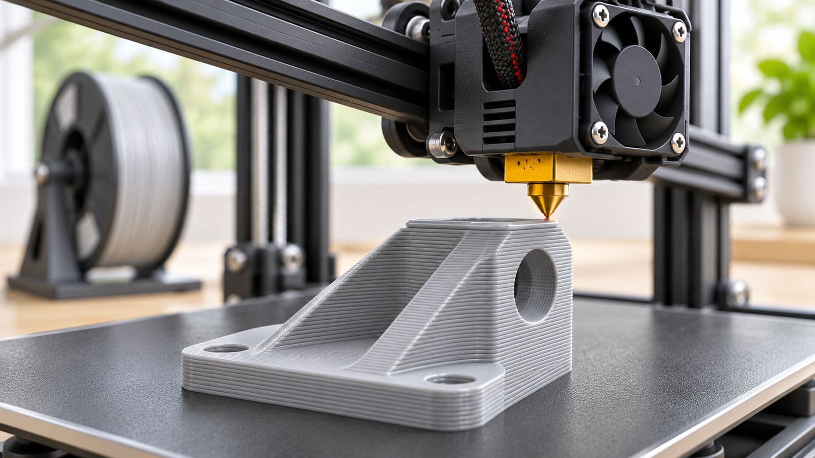
The decision rule that follows is purpose-driven. Choose milling when the prototype must prove strength, heat behavior, sealing or a tight interface, because only a solid, homogeneous part gives you that evidence. Consider a printed or cast near-net preform finished by milling when geometry dominates the purpose and the material is forgiving, since you pay for the near-net shape once rather than for a billet reduced to 20 percent of its mass in chips.
Build a Tolerance Plan Before You Request a Quote
A quote is only as good as the package behind it. Six items, in order:
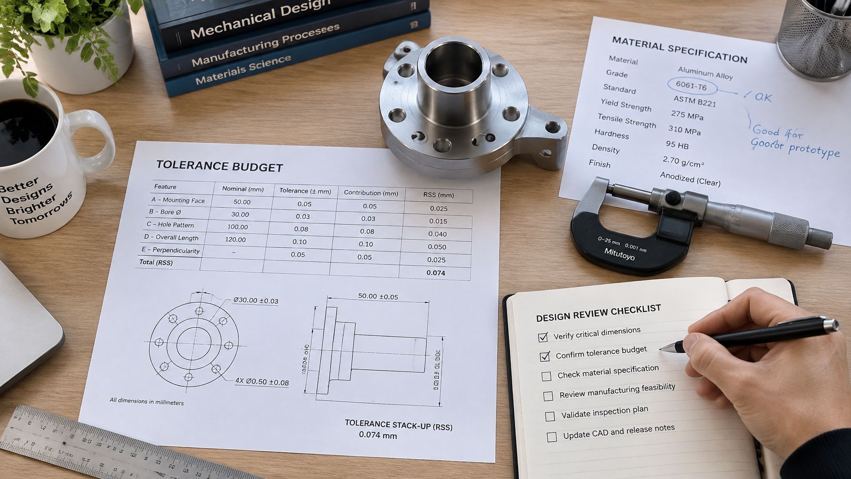
- Name the test each prototype must pass. Vibration, burst pressure, thermal cycling, a drop, or a fit check on the assembly line. This single sentence changes the tolerance plan.
- List the material with the final grade, or write down why a stand-in is acceptable for this build.
- Set the finish and mark cosmetic surfaces, so the shop prices only the faces that matter.
- State quantity and the date the parts are needed by, not the date you'd like to start.
- Attach a complete CAD file and a drawing with datums, thread callouts and general tolerance class.
- Flag the features you'll measure yourself, so inspection proves the same things you care about.
Then build the worksheet. One line per critical feature, nothing else.
| Feature | Test it serves | Tolerance | Inspection |
|---|---|---|---|
| Bearing bore | Shaft fit and rotation | ±0.01 mm | CMM |
| Dowel hole pair | Assembly alignment | Positional callout | CMM |
| Seal face | Leak test | Flatness 0.02 mm | Surface plate |
| Overall length | Envelope check | ISO 2768-1 medium | Calipers |
| Cosmetic top face | Appearance review only | General class | Visual |
The last step before release is a manufacturing review. A machinist-engineer reads the plan against the geometry and flags the corner radius that forces a second operation, the wall that will chatter, and the tolerance that no one will measure. FIRMFG provides free DFM feedback, with engineers reviewing designs and giving suggestions to optimize for CNC machining, plus a free CNC machining quote within 24 hours after you upload CAD files. With over 100 advanced CNC machines in-house, including 3-axis, 4-axis and 5-axis machining centers, a compound-angle housing and a flat bracket each go to the setup that suits them.
Ship the drawing with a purpose attached to every tight dimension and a schedule broken down by stage. FIRMFG cuts prototype parts in metals and engineering plastics, gives free DFM feedback on the features that add cost without adding evidence, and returns a free CNC quote within 24 hours of your CAD upload. Upload your STEP file at FIRMFG and see where your tolerance budget and your calendar go.