CNC Machining Tolerances: What Is Achievable in 2026
The most popular advice about CNC machining tolerances is a chart. Find your process, read the number next to it, copy that number onto the drawing, and trust the part to land inside it. That advice fails in both directions. It pushes engineers to pay for precision no function needs, and it lets them trust a band that the machine, the room temperature, or the inspection bench can't deliver.
A tolerance is a negotiation between what the part must do and what the process can prove. The drawing sets the requirement. The machine, the material, the thermal state at the moment of cutting, and the measurement method set what you get.
The parts that come back out of tolerance are rarely the ones with a badly chosen nominal dimension. They're the ones where nobody agreed on the conditions: which temperature, which fixture, which inspection method, and which features matter to the assembly.
Table of Contents
- Typical CNC Tolerances by Process at a Glance
- What a Tolerance Means on a Drawing
Size is only half the story
Default Tolerances When a Drawing Gives No Callout- What each class is for
What Pushes a Part Out of Tolerance- Why a warm machine is not the same machine
Proving a Tolerance With the Right Inspection Method- Matching method to band
Specifying Tolerances Without Overpaying- Material and geometry change the answer
Typical CNC Tolerances by Process at a Glance
| Process | Typical tolerance | When it applies |
|---|---|---|
| 3-axis CNC milling | ±0.1 to ±0.2 mm | Prismatic parts, standard setups |
| 5-axis CNC milling | ±0.05 to ±0.1 mm | Complex geometry, fewer re-clamps |
| CNC turning | ±0.05 to ±0.15 mm | Round parts such as shafts and bores |
| Standard general machining | ±0.05 mm | Common features without special finishing |
| Selected features with finishing passes | ±0.005 mm | Careful measurement and finishing passes |
Those process bands come from Zhongde's 2023 process reference, which lists ±0.1 to ±0.2 mm for 3-axis CNC milling, ±0.05 to ±0.1 mm for 5-axis CNC milling, and ±0.05 to ±0.15 mm for CNC turning. Read the 5-axis row carefully. The band is tighter partly because a 5-axis setup reaches more faces without re-clamping, so the datums stay consistent from feature to feature and error doesn't accumulate across setups.
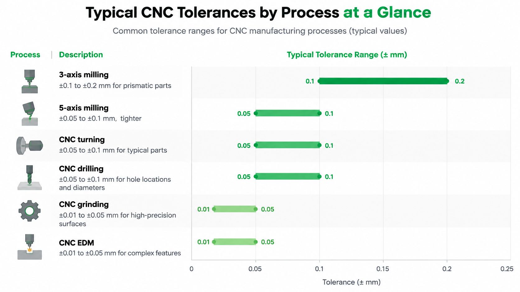
The general-machining figure sits at ±0.05 mm for common features with no special finishing, and selected features can reach ±0.005 mm when finishing passes and careful measurement are built into the plan, according to Davan Tech's 2026 tolerance guide. That last row is not a machine spec. It's a statement about the whole setup: a light finish cut, a stable part, a controlled room, and a measurement method that can resolve the band.
Take a 50 mm bore that the assembly needs at ±0.02 mm. That sits outside the 3-axis milling row. You have three honest options: put the bore on a lathe or a boring head with a finishing pass, redesign the fit so it tolerates a wider bore, or accept the risk and price the scrap. Tightening the number on the drawing doesn't create a fourth option.
Before you release a drawing, find the process row your part belongs to and check every critical feature against it. If a feature falls outside the band, you've found the cost driver before the quote did.
What a Tolerance Means on a Drawing
Think of a dartboard. The nominal dimension is the bullseye, and the tolerance band is the ring the part has to land inside to count. A shaft drawn at 10.00 mm passes if it measures anywhere from 9.95 to 10.05 mm when the drawing says ±0.05 mm. Nothing in that range is "better" than anything else in it. They all assemble.
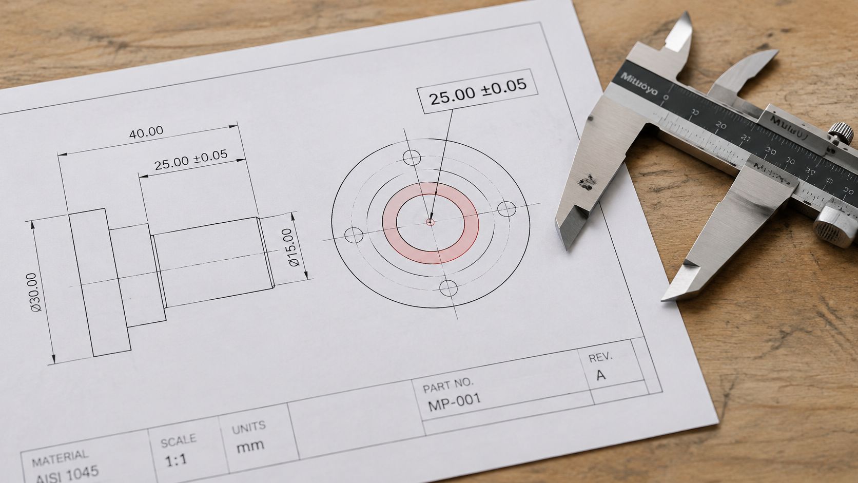
Tolerances appear in a few forms, and the form changes how the machinist sets the offset. A bilateral callout splits evenly above and below the nominal, as in 10.00 ±0.05. A unilateral callout puts the whole band on one side, as in 25.00 +0.05/-0.00, which tells the shop to aim at the low end and never cross nominal. Limit dimensions skip the plus and minus entirely and state the maximum and minimum directly, which removes ambiguity but makes stack-up math more tedious.
Size is only half the story
Size tolerance governs diameter, length and thickness. Geometric tolerance governs form, orientation, location and the relationship to datums, and it lives in the feature control frame. A shaft can measure a perfect 10.00 mm at every cross-section and still be bent, oval, or drilled off position. That's why a diameter callout alone won't save an assembly that needs a true position control on a bolt circle; if that's the gap in your print, the plain-language walkthrough of the true position symbol covers how the frame is read and what the bonus tolerance does to your acceptance zone.
Four terms come up in every tolerance conversation, and they're worth separating:
- Nominal: the design dimension, the ideal the drawing is built around.
- Limit: the maximum and minimum permitted sizes, which is what inspection compares against.
- Fit: the resulting clearance or interference between two toleranced features, which is what the assembly feels.
- Datum: the reference from which location and orientation are measured, and the reason setup order matters.
The useful mental model: the tolerance band is what you accept. Process capability is what you get. Measurement capability is what you can prove. A part only ships when all three agree.
Treat every tolerance as a line between cost and risk, not as a grade of quality. A wide band on a cosmetic edge costs nothing and protects nothing. A narrow band on a bearing seat buys reliability and costs a finishing pass. The engineering work is deciding which features deserve which.
Default Tolerances When a Drawing Gives No Callout
Most dimensions on a real drawing carry no individual tolerance. Instead the title block cites a general tolerance class, and the shop applies ISO 2768-1 by nominal size. The standard runs from fine to very coarse, so the same 25 mm feature has four different permitted deviations depending on which class the print names.
| Nominal size (mm) | f (fine) | v (very coarse) |
|---|---|---|
| 0.5 to 3 | ±0.05 | – |
| Over 3 to 6 | ±0.05 | ±0.50 |
| Over 6 to 30 | ±0.10 | ±1.00 |
| Over 30 to 120 | ±0.15 | ±1.50 |
Read a row in two steps. Find the band that contains your nominal size, then find the class the drawing cites in its general tolerance note. Between those columns sit the medium and coarse classes most shops work to: ±0.10 mm for fine, ±0.20 mm for medium and ±0.30 to ±0.50 mm for coarse in the small and mid-size bands. Anything under 0.5 mm nominal needs an explicit tolerance, because the standard doesn't cover it.
What each class is for
Fine suits functional dimensions where an assembly depends on the result but no individual callout was worth the drafting time. Medium is the practical default for general machining, and it's what most shops assume when the title block is silent. Coarse covers non-critical edges, clearance features and anything where a millimetre of variation changes nothing. Very coarse exists for heavy fabrications and rough stock.
Supplier guides don't always agree with the table. JF Manufacturer's 2025 tolerance guide lists ISO 2768-style linear tolerances of ±0.1 mm for nominal lengths up to 6 mm, ±0.2 mm for lengths over 6 to 30 mm, and ±0.8 mm for lengths over 400 to 1,000 mm, which reads as a medium-class interpretation at the small end and drifts at the large end. Two suppliers quoting the same untoleranced part can therefore be working to different numbers, which is exactly why the class belongs in the title block rather than in a conversation.
Work an example. A 25 mm plate edge with no callout under class m falls within ±0.2 mm, so it can be milled in a single roughing pass with no finishing step and no inspection beyond a caliper check. Now make that same edge a locating shoulder for a mating bracket, and the general block stops being adequate. The dimension needs its own callout, its own datum reference, and a stated inspection method.
If a feature can cause a rejection at assembly, it should carry its own tolerance. The general block is a convenience for everything that can't.
What Pushes a Part Out of Tolerance
Ask most engineers why a process drifts and you'll hear about tool wear and fixturing. Those matter, but they're not the biggest term. Thermal behavior dominates, and NIST reports that thermal errors can contribute up to 75% of total machining error in some machine-tool conditions, according to NIST's work on machining accuracy.
The mechanism is straightforward once you picture it. Motors warm up. The spindle runs for hours. Cutting heat enters the tool, the chip and the workpiece. Coolant temperature shifts. The room warms through the afternoon. Each of those effects deforms the machine structure or the part and shifts the relative position between tool and workpiece by amounts that are invisible on the display.
Why a warm machine is not the same machine
A machine that verifies beautifully at 7 a.m. can drift outside a tight band by noon during a long production cycle. NIST's guidance is to validate tolerance with the warm-up state, cycle duration, coolant temperature, workpiece temperature, and the location of the feature inside the work volume all accounted for, because those variables move the result.
NIST describes two control strategies. Thermal-error avoidance uses low-expansion structures, better lubrication, cooling, and designs that are less heat-sensitive. Thermal-error compensation builds a predictive model from measured machine behavior and corrects the tool path or NC code to offset the predicted shift, an approach earlier NIST work applies to both geometric and thermally induced error.
Ask for conditions, not just numbers. "Hold ±0.01 mm" is not a specification. "Hold ±0.01 mm after thermal stabilization, under the stated cutting and inspection conditions, with first-article verification at the production setup" is.
The other causes worth budgeting for
- Material response. Aluminum, steel and engineering plastics expand at different rates and resist cutting differently, so the same program produces different results across them.
- Thin walls and clamping load. A 1 mm wall deflects under the fixture before the cutter touches it, then springs back after unclamping into a shape nobody programmed.
- Residual stress. Roughing releases stress locked into rolled or forged stock. The part moves after the fixture comes off, and a finish pass on relaxed geometry may not recover it. Rough, stress-relieve, then finish.
- Tool deflection and wear. A long-reach end mill bends away from the cut under load, and a worn edge rubs instead of shearing. Both show up as size drift across a run rather than scrap on a single part.
- Machining sequence. Cutting a tight bore before a nearby pocket removes the support that kept the bore round, and the bore goes oval.
Proving a Tolerance With the Right Inspection Method
A tighter drawing number does not guarantee a better part. A feature can sit inside its stated limits and still fail conformity, because the method used to check it may not be capable of proving anything at that scale.
Three capabilities get confused in procurement conversations. Machine capability is what one machine repeats under one setup. Process capability is what production holds across batches, shifts and operators. Measurement capability is whether the inspection method can resolve the band with enough margin to make a confident decision. The third is the one nobody budgets for.
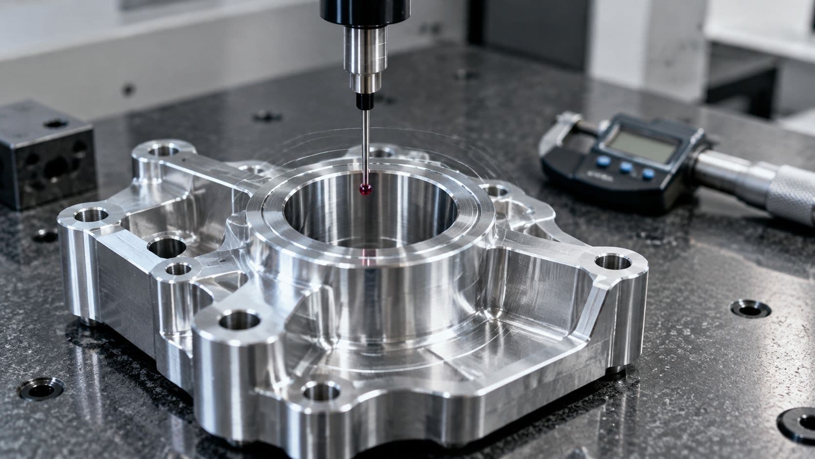
The gap is not theoretical. A 2025 study applying ISO 22514-7:2021 found a CNC machine tool setup could not verify a 15 µm tolerance, with the CMM's minimum reported measurement tolerance at 13.7 µm against 26.2 µm for the CNC machine tool measurement setup, published in the International Journal of Advanced Manufacturing Technology. The tolerance existed on paper. The setup could not confirm it.
A common practice is to keep measurement uncertainty to a fraction of the part tolerance, so a ±0.01 mm band needs an inspection method that resolves well inside that band. If the gauge, probe routine or environmental state consumes most of the zone, the reading becomes a vote rather than evidence.
Matching method to band
- CMM: three-dimensional features, GD&T, position and profile, and anything where the datum reference frame has to be reproduced in software. Slower, and worth it on critical geometry.
- Calibrated digital calipers: general linear dimensions well outside the measurement-uncertainty limit. Fast, and frequently over-trusted on tight bands.
- In-machine probing: quick checks during the run without breaking setup, best for catching drift rather than certifying a part.
- Optical measurement: small, soft or easily deformed features where a contact probe would move the surface it is measuring.
- Go/no-go functional gauges: production fits where the question is whether the mating part goes on. Fastest acceptance decision available.
Temperature, fixturing, sampling plan and repeatability decide whether a result can be trusted. A part measured straight off a warm machine, resting on a cold granite plate, is being measured in a state it will never see in service. Pair each tolerance band with a realistic inspection strategy and write the conformity decision rule next to the band; that discipline closes a recurring gap in prototype and low-volume work, and the broader principles sit in this guide to quality control in manufacturing.
Specifying Tolerances Without Overpaying
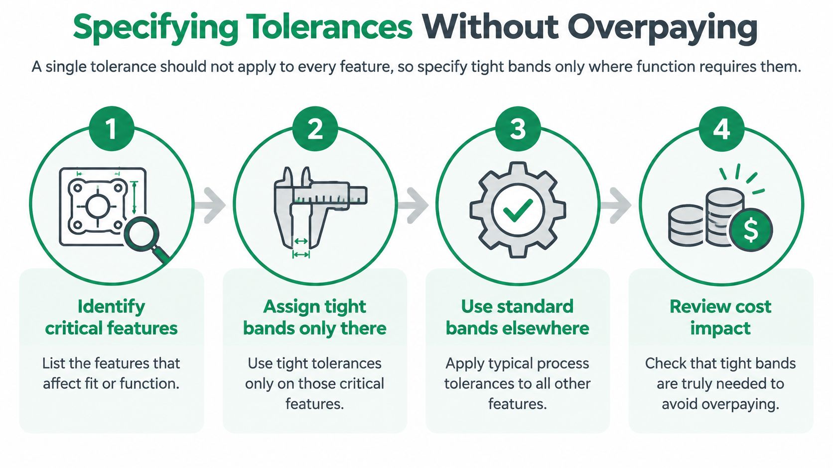
Most overpayment on machined parts is self-inflicted: a blanket tight tolerance applied to features that never needed it. Specify tight bands only where function demands them, and let everything else fall to a general class. That single decision removes more cost from a part than any negotiation over hourly rates.
Follow a routine, and know why each step exists:
- List the functional features first. Bearing seats, sealing diameters, precision locating holes and mating bores are the short list. These are the features that cause a rejection at assembly, so they earn individual attention.
- Pick a primary datum from how the part sits in the assembly. If the part locates on its base in service, it should locate on its base in the fixture and in the CMM program. A different datuming scheme measures a different part than the one that ships.
- Apply tight bands only to those features. Everything else drops to the general class, which is where the savings live.
- Use position tolerance for hole patterns. Controlling a pattern to functional datums beats stacking coordinate dimensions, and it gives the shop bonus tolerance when holes run at maximum material condition.
- State the conditions that change results. Material condition, surface finish, burr limits and the thermal state at inspection all consume part of a small zone. Left unstated, those decisions go to whoever measures last.
- Run the stack-up both ways. Worst-case analysis suits assemblies that must be guaranteed; statistical analysis fits cases where economically justified variation is acceptable. Choosing between them is a design decision, and ASME identifies Y14.5 as the authoritative GD&T standard for expressing that intent.
- Confirm the inspection method can prove the band before release. A check that can't resolve the tolerance makes the tolerance a wish.
Material and geometry change the answer
The same ±0.1 mm is a different promise on a small steel bracket, a large aluminum plate and an engineering-plastic housing. Published manufacturing research reports that thermal error may account for approximately 40 to 70% of total machining error on machine tools, per correlation studies on machining accuracy. Digital verification of aluminum parts can also show larger and less repeatable error than contact methods, so the measurement method has to be checked against the tolerance band before the drawing goes out. Tolerance is a property of the part in its environment, and a drawing that ignores that invites a dispute at inspection.
| Feature | Tolerance approach | Drawing note |
|---|---|---|
| Bearing seat or press-fit bore | Tight, set by the fit class | Reference the datum scheme |
| Sealing diameter or groove | Tight, control form and position | Add geometric tolerance and conditions |
| Clearance hole | Broad, use the general class | State the general class in the title block |
| Cosmetic or non-functional edge | Coarse ISO class or general block | No individual callout needed |
| Large or flexible plate | Set at stated temperature and support | Specify thermal state for inspection |
Tight bands cost real money: extra finishing passes, slower feeds, more inspection time, and a higher chance of rework. Those are the same levers that drive CNC milling cost on any prototype or short run. A blanket tight tolerance spreads that cost across every dimension on the part while leaving the one relationship that matters to assembly under-defined. That is the expensive version of precision.
The checklist before release: mark three to five critical features, state the datum scheme and the inspection temperature, and ask for DFM feedback on whether each band is realistic for the chosen process.
We inspect with a CMM and calibrated digital calipers, and we document results against CAD nominal values and the tolerances on the print, so acceptance is a record instead of a conversation. If a band can't be verified, we say so before the run.
Upload your CAD files to FIRMFG and we'll return a free CNC machining quote within 24 hours, with DFM notes on any tolerance that will drive cost or risk on your part. We machine metal and plastic prototypes and low-volume runs on 3-, 4- and 5-axis equipment, with tolerances to ±0.005 in as standard and as tight as ±0.0005 in where the geometry and material support it. Send the drawing with your datum scheme and inspection conditions, and we'll tell you which features we can prove and how.